EP0941408B1 - Aktuator mit driftfreier klemmung bei stromausfall - Google Patents
Aktuator mit driftfreier klemmung bei stromausfall Download PDFInfo
- Publication number
- EP0941408B1 EP0941408B1 EP97948593A EP97948593A EP0941408B1 EP 0941408 B1 EP0941408 B1 EP 0941408B1 EP 97948593 A EP97948593 A EP 97948593A EP 97948593 A EP97948593 A EP 97948593A EP 0941408 B1 EP0941408 B1 EP 0941408B1
- Authority
- EP
- European Patent Office
- Prior art keywords
- piston
- valve
- spool
- friction pad
- line
- Prior art date
- Legal status (The legal status is an assumption and is not a legal conclusion. Google has not performed a legal analysis and makes no representation as to the accuracy of the status listed.)
- Expired - Lifetime
Links
Images

Classifications
-
- F—MECHANICAL ENGINEERING; LIGHTING; HEATING; WEAPONS; BLASTING
- F15—FLUID-PRESSURE ACTUATORS; HYDRAULICS OR PNEUMATICS IN GENERAL
- F15B—SYSTEMS ACTING BY MEANS OF FLUIDS IN GENERAL; FLUID-PRESSURE ACTUATORS, e.g. SERVOMOTORS; DETAILS OF FLUID-PRESSURE SYSTEMS, NOT OTHERWISE PROVIDED FOR
- F15B15/00—Fluid-actuated devices for displacing a member from one position to another; Gearing associated therewith
- F15B15/20—Other details, e.g. assembly with regulating devices
- F15B15/26—Locking mechanisms
-
- F—MECHANICAL ENGINEERING; LIGHTING; HEATING; WEAPONS; BLASTING
- F15—FLUID-PRESSURE ACTUATORS; HYDRAULICS OR PNEUMATICS IN GENERAL
- F15B—SYSTEMS ACTING BY MEANS OF FLUIDS IN GENERAL; FLUID-PRESSURE ACTUATORS, e.g. SERVOMOTORS; DETAILS OF FLUID-PRESSURE SYSTEMS, NOT OTHERWISE PROVIDED FOR
- F15B13/00—Details of servomotor systems ; Valves for servomotor systems
- F15B13/02—Fluid distribution or supply devices characterised by their adaptation to the control of servomotors
- F15B13/04—Fluid distribution or supply devices characterised by their adaptation to the control of servomotors for use with a single servomotor
- F15B13/042—Fluid distribution or supply devices characterised by their adaptation to the control of servomotors for use with a single servomotor operated by fluid pressure
- F15B13/043—Fluid distribution or supply devices characterised by their adaptation to the control of servomotors for use with a single servomotor operated by fluid pressure with electrically-controlled pilot valves
- F15B13/0436—Fluid distribution or supply devices characterised by their adaptation to the control of servomotors for use with a single servomotor operated by fluid pressure with electrically-controlled pilot valves the pilot valves being of the steerable jet type
-
- F—MECHANICAL ENGINEERING; LIGHTING; HEATING; WEAPONS; BLASTING
- F15—FLUID-PRESSURE ACTUATORS; HYDRAULICS OR PNEUMATICS IN GENERAL
- F15B—SYSTEMS ACTING BY MEANS OF FLUIDS IN GENERAL; FLUID-PRESSURE ACTUATORS, e.g. SERVOMOTORS; DETAILS OF FLUID-PRESSURE SYSTEMS, NOT OTHERWISE PROVIDED FOR
- F15B20/00—Safety arrangements for fluid actuator systems; Applications of safety devices in fluid actuator systems; Emergency measures for fluid actuator systems
- F15B20/002—Electrical failure
-
- F—MECHANICAL ENGINEERING; LIGHTING; HEATING; WEAPONS; BLASTING
- F15—FLUID-PRESSURE ACTUATORS; HYDRAULICS OR PNEUMATICS IN GENERAL
- F15B—SYSTEMS ACTING BY MEANS OF FLUIDS IN GENERAL; FLUID-PRESSURE ACTUATORS, e.g. SERVOMOTORS; DETAILS OF FLUID-PRESSURE SYSTEMS, NOT OTHERWISE PROVIDED FOR
- F15B2211/00—Circuits for servomotor systems
- F15B2211/80—Other types of control related to particular problems or conditions
- F15B2211/86—Control during or prevention of abnormal conditions
- F15B2211/862—Control during or prevention of abnormal conditions the abnormal condition being electric or electronic failure
- F15B2211/8623—Electric supply failure
-
- F—MECHANICAL ENGINEERING; LIGHTING; HEATING; WEAPONS; BLASTING
- F15—FLUID-PRESSURE ACTUATORS; HYDRAULICS OR PNEUMATICS IN GENERAL
- F15B—SYSTEMS ACTING BY MEANS OF FLUIDS IN GENERAL; FLUID-PRESSURE ACTUATORS, e.g. SERVOMOTORS; DETAILS OF FLUID-PRESSURE SYSTEMS, NOT OTHERWISE PROVIDED FOR
- F15B2211/00—Circuits for servomotor systems
- F15B2211/80—Other types of control related to particular problems or conditions
- F15B2211/875—Control measures for coping with failures
- F15B2211/8752—Emergency operation mode, e.g. fail-safe operation mode
Definitions
- This invention relates to an electro-hydraulic actuating system, and more particularly, to a failfixed piston device that will failfix the piston upon loss of electrical power to the system, and will have a zero drift rate for an indefinite period of time after having failfixed, and a clamping device for failfixing the piston device.
- An actuator according to preamble of claim 1 is known from DE-A-33 15 056.
- EHSV Electro-Hydraulic ServoValves
- Actuators and metering devices have been controlled in the past by Electro-Hydraulic ServoValves (EHSV). These EHSV's interact between an electrical control signal and an actuator or metering device.
- EHSV Electro-Hydraulic ServoValves
- FADEC Full Authority Digital Electronic Control
- the generated electrical control signal from the FADEC is connected to an EHSV having a first stage torque motor, or other electro-mechanical device, and a second stage spool, which generally controls a hydraulic piston which in turn controls fuel to the engine.
- the hydraulic piston is connected to a Linear Variable Differential Transformer (LVDT) or the like, where the LVDT sends a feedback signal or an actual position signal of the piston to the FADEC.
- LVDT Linear Variable Differential Transformer
- an EHSV provides a hydraulic output signal which controls the movement of an actuator piston or metering valve piston which moves in a cylinder to generate a mechanical output signal which varies the position of the mechanical device or mechanical fuel metering valve.
- the flight characteristic or engine speed can be accurately controlled as a function of the electrical signal generated by FADEC.
- a hydraulic lock is generated on the second stage spool, which in turn locks the hydraulic piston.
- a hydraulic lock may be achieved by the second stage spool or by a separate cutoff valve which is activated by the second stage spool.
- the hydraulic lock on the second stage spool has a drift rate associated therewith due to lap leakage effects, i.e. the leakage of hydraulic fluid passed the lands of the second stage spool. Further, the drift rate varies depending on the external load, i.e. the force acting against the hydraulic piston.
- the prior art will, upon loss of electrical signal, remain failfixed only for a short period of time, and must be constantly corrected to maintain the position of the second stage spool having the hydraulic lock thereon.
- Some prior art failfixing valves use differential current of an input signal to position a spool within a servovalve which in turn allows hydraulic fluids of different pressures to flow through selected ports to opposite ends of a servopiston to position such servopiston and the controlled actuator or the like.
- the differential current returns to zero, which in turn moves the spool to the median position.
- the prior art failfixed servovalve is deemed adequate in many applications, the controlled actuator or metering valve will drift from the locked position after a short period of time because lap leakage effects or because of external loads on the controlled actuator or controlled metering valve, and thus introduce an undesirable condition in the controlled system.
- the present invention provides an electro-hydraulic system with a new and improved failfixed locking means which upon loss of the electrical input signal to the electro-hydraulic system results in the output actuator being locked/fixed in its present desired position.
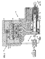
- the actuator control system 10 includes an electro-hydraulic servovalve (EHSV) 12 and an actuator valve 14 operatively associate therewith.
- the EHSV 12 comprises a housing 16 defining a double acting torque motor 18, a first stage jet pipe 56, a second stage axially translatable spool 22 disposed within a second stage valve chamber 20, a cutoff valve chamber 24, and an axially translatable cutoff spool 26 disposed within a cutoff valve chamber 24.
- the housing 16 has five fluid lines connecting therethrough, line 28 is connected to an unregulated supply-means (not shown) to receive fluid at a supply pressure (PF), fluid line 30 is connected to a drain reservoir (not shown) which is maintained at a generally constant drain pressure (PD) which is at a pressure less than the supply pressure, fluid line 32 is connected to lock valve 69 at a desired pressure which can be either PF or PD, and drain lines 34, 36 are connected in fluid communication with the second stage valve chamber 20 to provide a desired fluid pressure to the actuator valve 14.
- PF supply pressure
- PD drain pressure
- drain lines 34, 36 are connected in fluid communication with the second stage valve chamber 20 to provide a desired fluid pressure to the actuator valve 14.
- Actuator valve 14 comprises a housing 38 defining a valve chamber 40, an axially translatable spool 42 disposed within the valve chamber 40, and a bias spring assembly 44 disposed within the valve chamber 40 in operative association with a failfixed locking valve 69.
- the spool 42 has an eyelet 46 attached thereto, e.g. by way of the thread means 48 , which may be utilized on an aircraft (not shown), and more specifically in conjunction with the control of various mechanical variables associated with a jet aircraft engine, e.g. jet engine vanes.
- the actuator control system 10 further includes an electronic engine control device (EEC) 50 that is responsive to signals on line 52 from sensors 54 located on the jet engine and on the air frame e.g. power lever position and engine temperature.
- EEC electronic engine control device
- the sensors 54 sense various jet engine parameters such as engine speed, and the EEC 50 is responsive, in part, to the signals 52 to control the movement of the vanes connected to the eyelet 46.
- the flow of fluid through the second stage valve chamber 20 and the cutoff valve chamber 24 depends upon the position of the axially translatable spools 22 and 26, respectively. More specifically, the fluid flowing through the second stage and cutoff valve chambers 20, 24 depends upon the position of the "lands" and “metering windows” on the spool members with respect to the supply and drain lines connected in the fluid communication therewith.
- the "lands” define circumfrentially extending portions 81, 82, 83, 84 of the axially translatable second stage spool 22, and portions 86, 87, 88, 89 of axially translatable cutoff spool 26.
- the EEC device 50 provides electrical signals through electrical lines 53, 55 to the double acting torque motor 18.
- the double acting torque motor 18 magnetically deflects a first stage flexible jet pipe 56 to direct hydraulic fluid PF through hydraulic lines 21, 23 to both ends of the axially translatable second stage spool 22 in the second stage valve chamber 20.
- the axially translatable spool 22 moves in either of two directions, depending upon the pressure differential of the hydraulic fluid applied to the ends of the axially translatable spool 22.
- the axially translatable spool 22 allows hydraulic fluid to flow either through the drain lines 61, 62, 63 and then through the fluid line 30, or through the pressure supply lines 64, 65, 66, 67, 68 which supply high pressure fluid PF to the cutoff valve chamber 24.
- the axially translatable spool 22 also allows hydraulic fluid to flow from pressure supply lines 64, 65, 66, 67, 68 to both ends of the spool 26, to the fluid line 32, and to fluid lines 34, 36 through annuluses 77, 78 .
- the spool 26 also allows fluid to flow from PL fluid line 32 to PD drain line 51.
- the actuator valve 14 has a linear variable displacement transducer (LVDT) 70 extending axially through a portion of the spool 42 in the valve Chamber 40.
- the LVDT 70 transmits signals to the EEC device 50 indicative of the actual position of the spool 42 in the valve chamber 40.
- Signals from the EEC 50 are coupled to the double acting torque motor 18 to control the torque motor in order to drive the flexible jet pipe 56, and in turn adjust the pressure differential between ends of the axially adjustable spool 22, so as to control the axial position of the spool 42.
- the actuator valve housing 38 defines the valve chamber 40 and the failfixed chamber 60.
- the failfixed chamber 60 defines a circumfrentially extending annular chamber disposed between the housing 38 and the spool 42, and failfixed locking valve 69 and the bias spring assembly 44 are disposed therein.
- the failfixed chamber 60 has four fluid ports opening through its wall; port 91 which is connected in fluid communication through the fluid drain line 30 to the low pressure drain, port 92 which is connected in fluid communication through a fluid lock valve line 32 to annulus 76 at either PD or PF, port 93 which is connected in fluid communication through the fluid line 36 to annulus 78 and port 94 which is connected in fluid communication through fluid line 34 to annulus 77.
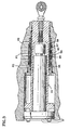
- the failfixed locking valve 69 defines a cylindrical locking piston or sleeve 96 which is circumferentially spaced from the spool 42 so that in normal operation the spool 42 slides freely through the locking piston or sleeve 96.
- the cylindrical locking piston 96 as shown in detail in FIG. 3, has a plurality of apertures 97 through the sidewall 98 and spaced around the periphery of the sleeve with each aperture 97 having a friction pad 99 disposed therein.
- the friction pad 99 may be a thermoplastic material, e.g. peek or Vespel (Registered Trademark of DuPont). The friction pad 99 moves radially in the aperture 97 to apply a clamping force to the spool.
- the outer portion of the sidewall 98 has a circumferential groove extending axially beyond each aperture 97 with a flexible bladder-like member 90 secured in the groove 94.
- the bladder 90 which may be an elastic material, e.g. Viton, is in contact with the friction pad 99 on one side and in fluid communication with either PD or PL on the opposite side. The bladder prevents hydraulic fluid from flowing through the apertures 97 to the spool 42, and transmits a clamping pressure from PL to the friction pads 99 for clamping the spool 42 against movement.
- axially translatable spool 26 is in the leftward position as shown in FIG. 1, and supply fluid PF enters the fluid line 28 and flows into either or both the supply line 17 of the flexible jet pipe 56, and/or the supply line 19 of the second stage valve chamber 20.
- the position of the axially translatable spool 22 is controlled by the EEC 50, based on the signal transmitted by the LVDT 70 which is indicative of the actual position of the actuator spool 42.
- the EEC 50 is responsive to the actual and desired position signals transmitted to control the double acting torque motor 18 in order to adjust the flexible jet pipe 56.
- Movement of the jet pipe 56 adjusts the differential pressure between a first inlet end line 21 and a second inlet end line 23 in order to control the position of the axially translatable spool member 22, and thus control the flow of hydraulic fluid through the cutoff valve chamber 24 and to the valve chamber 40 of the actuator valve 14.
- the actuator valve 14 controls jet engine vanes (not shown) which are connected to the eyelet 46, and it is desired to open or close the vanes as engine speed changes it is necessary to move the spool 42 and the eyelet 46 attached to the vanes.
- EEC 50 transmits a desired signal to the double acting torque motor 18 to move the flexible jet pipe 56 to the left as shown to increase the flow of the supply pressure PF in the second inlet end line 23 which in turn shuttles the first stage axially translatable spool 22 to the right.
- the center drain line 62 opens to drain hydraulic fluid from the right side of valve chamber 40 through fluid line 34, annulus 77, bypass line 75, and annulus 72, while supply pressure is supplied to the left portion of valve chamber 40 through fluid line 36, annulus 78, bypass line 79, annulus 73, and supply line 19 thereby moving the spool 42 and the eyelet 46 to the right as shown by the arrow 47 to a decreased engine speed position.
- the range of control current from EEC 50 to the double acting torque motor 18 is entirely positive never passing through zero current.
- the position of axially translatable spool 22 is proportional to the current of the double acting torque motor 18 and in turn, as previously described, the size of the openings from drain line 62 to the right side of valve chamber 40 and from supply line 19 to the left side of chamber 40 would be proportional to the position of axially translatable spool 22 if the actuator spool 42 is moving to the right. Therefore, the velocity of the actuator spool 42 is proportional to the current supplied to torque motor 18 .
- the normal operating range is greater than 0 ma current, thereby resulting in axially translatable spool 22 having a unique 0 ma position outside the normal operating range.
- the lock valve fluid line 32 is switched from the low pressure drain PD at line 51 to the high pressure supply PF through hydraulic line 65, annulus 71, supply line 19 and fluid supply line PF 28.
- the high supply pressure in lock valve fluid line 32 is ported to the failfixed locking valve 69 through port PL 92 which causes the thermal plastic friction pad 95 to be forced against the spool 42 thereby achieving a friction lock on the spool 42.
- the spool 42 is now drifting to the right.
- the failfixed locking valve 69 being friction locked to spool 42, moves with spool 42. As failfixed locking valve 69 moves it opens a fluid flow path from the left side of valve chamber 40 to the low pressure drain in line 91.
- a fluid flow path is opened from what is now supply pressure PF in line 92 to the right side of valve chamber 40.
- the actuator spool 42 will drift to the right until two openings just described are equal to the orifices 57 and 85. At this point an equalization is achieved between the flow from annulus 73 to the left side of valve chamber 40 and the flow from valve chamber 40 to line 91. Also, an equalization of flow is achieved between the flow from line 92 to the right side of valve chamber 40 and the flow from valve chamber 40 to annulus 72. This would be referred to as a hydraulic null. In this manner the rightward drift of actuator spool 42 stops and will remain stopped for an indefinite period of time.
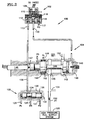
- the FMU 100 includes a double-acting torque motor 102, a single stage metering valve 104, and a fluid cut-off valve 106 operatively associated each with the other.
- the torque motor 102 known to those skilled in the art, comprises a bi-polar input current device 108, a flapper system 110 and a plurality of fluid ports 112, 114, 116.
- the bi-polar input current device moves the flapper system 110 in one direction when positive current is applied to its coils and moves it in the opposite direction when negative current is applied.
- the fluid ports 112, 114, 116 are in fluid communication with regulated servo supply pressure (PR) line 113, flapper modulated pressure (PM) line 115, and drain pressure (PD) line 117, respectively.
- PR regulated servo supply pressure
- PM flapper modulated pressure
- PD drain pressure
- a high pressure filtered fuel supply system 120 is coupled in fluid communication with the metering valve 104 through filtered high pressure (PF) fuel line 122, and with various servo-driven components through fuel line 124 in order to provide a filtered relatively high pressure source of fuel to these components.
- the fuel line 124 is connected in fluid communication through a pressure regulating valve, of a type known to those skilled in the art (not shown) which supplies regulated pressure (PR) fuel to inlet port 126 of the fluid cut off valve 106.
- PR regulated pressure
- the fluid cut off valve 106 comprises a housing 130 defining cut off valve chamber 132, a regulated pressure cut off valve axially translatable spool 134 disposed within the cut off valve chamber 132 and a spring bias assembly 136 operatively connected to the PR spool 134.
- the housing 130 has four fluid lines connecting therethrough, the PR inlet port 126, a PD drain line 127 connected to a drain reservoir (not shown), a PL locking line 125 connected to a lock valve (e.g. fluid line 32) at a desired pressure which can be either PF or PD, and PR outlet line 128.
- the axially translatable PR cutoff valve spool 134 is normally biased in one direction by the spring bias assembly 136 and can be moved in the other direction when the pressure in the PL locking line 125 is switched to high pressure PF.
- Metering valve 104 comprises a housing 140 defining a metering valve chamber 142, and axially translatable spool 144 disposed within the metering valve chamber 142, a failfixed locking valve 146 in operative association with the axially translatable metering spool 144, and a linear variable displacement transducer (LVDT) 148 operatively connected to the axially translatable metering spool 144 for providing electronic signals to the EEC 50 indicative of the actual position of the axially translatable metering spool 144 in the metering valve chamber 142.
- LVDT linear variable displacement transducer
- the axially translatable metering spool 144 moves in either of two directions, depending upon the pressure differential of the fuel applied to the ends of the axially translatable metering spool 144.
- the axially translatable metering spool 144 controls the amount of fuel flowing through the high pressure (PS) fuel line 122 through a portion of the window 143 through pilot line 150 which supplies fuel to a set of pilot nozzles (not shown).
- PS high pressure
- fuel is supplied from the high-pressure fuel system 120 to the annular recess 145 through the metering window 143 and coupled in fluid communication with the pilot line 150.
- the position of the axially translatable metering spool 144 within the metering valve chamber 142 which controls the amount of fuel flowing in the pilot line 150, is controlled by fluid flow into or out of metering valve chamber 142, via line 117.
- the regulated servo supply pressure PR flows through the fluid cut off valve 106, PR outlet line 128, through half area metering valve chamber 147 and is supplied to the double acting torque motor 102 through regulated servo supply pressure PR line 113.
- the flapper system 110 normally maintains an equal opening between lines 113, 117, and 116 such that flow in line 113 equals flow in line 116, and there is zero net flow in line 117. This is the null position of the flapper system 110, and corresponding to zero torque motor current.
- the axially translatable metering spool 144 is constructed in such a predetermined manner that the spool face area on the PR side (left side as shown) is one half of the spool area on the PM side (right side as shown).
- the axially translatable metering spool 144 when the PM is equal to one half of PR the axially translatable metering spool 144 will be balanced, but as PM increases greater than one half PR then the axially translatable metering spool 144 will move to the left (as shown in FIG. 2). Due to the characteristic of the bi-polar input current device 108, and because the deflecting flapper means 111 is normally in the mid position with respect to nozzle 118 and nozzle 119 , the axially translatable metering valve spool is normally balanced and not moving.
- a control signal is sent to the double acting torque motor 112 to increase the current in the positive direction which will move the deflecting flapper means 111 away from nozzle 119 and toward nozzle 118 closing off PR fluid flow from line 113 thus decreasing the fluid pressure PM in fluid line 117 thereby decreasing the pressure against the right side of axially translatable metering spool 144 thereby shuttling said spool to the right and increasing fuel flow through pilot line 150.
- the flapper system 110 moves to its "null" position as described above and the pressure in PL looking line 125 changes to high pressure fluid, e.g. PL pressure coming from the EHSV 12 as previously described, and moves the axially translatable regulator pressure cut off valve spool 134 to the right.
- Spool 134 cuts off PR flow through line 113 and this causes all pressures in double acting torque motor system 102 and metering valve 104 to drop to PD, except in PL fluid line 149.
- the pressure in lines 113 and 117, and valve chambers 147 and 142 decrease to PD, thereby equalizing such pressures, and in this manner, any pressure load tending to move spool 144 is eliminated.
- the failfixed locking valve 146 has high pressure fluid applied through the PL fluid line 149 which causes the thermal plastic friction pad 152 to be forced against the axially translatable metering spool 144 thereby achieving a friction lock on the spool 144 and holding it statically positioned against external vibratory loads.
Claims (7)
- Aktuator zum Positionieren einer Baugruppe mit einem in einer Bohrung bewegbaren Kolben (42) und einem elektrohydraulischen Servoventil (12) zur Kontrolle eines Fluiddrucks von und zu dem Kolben, um den Kolben in Folge eines elektrischen Signals zu bewegen, wobei der Aktuator ein Ausfall-Fixier-Ventil (failfixed valve) (69) aufweist, das den Kolben bei Ausfall eines elektrischen Signals in einer festgelegten Position hält, dadurch gekennzeichnet, dass das Ausfall-Fixier-Ventil umfässt:Buchsenmittel (96) die einen Teil des Kolbens eng anliegend umgeben, wobei die Buchsenmittel umlaufend angeordnete und durchgehende Durchlassmittel (97) aufweisen,Reibbelagmittel (99), die zur Aufnahme in den Durchlassmitteln geeignet sind, wobei die Reibbelagmittel in den Durchlassmitteln radial bewegbar sind,flexible Buchsenmittel (90), die einen Bereich der Buchsenmittel umgeben, wobei die flexiblen Buchsenmittel die Reibbelagmittel eng anliegend kontaktieren undVentilmittel (18,20,26,56), die bei Ausfall des elektrischen Signals betriebsbereit zum Ablassen des Fluiddrucks aus dem Kolben und zur Speisung der flexiblen Buchsenmittel mit einem Absperrdruck ausgebildet sind, wobei die flexiblen Buchsenmittel den Absperrdruck an die Reibbelagmittel übertragen, wodurch die Reibbelagmittel gegen den Kolben wirken, so dass der Kolben in einer festgelegten Position einspannbar ist.
- Aktuator nach Anspruch 1, in dem die Ventilmittel ein zum Empfang eines elektrischen Signals ausgebildetes Erst-Stufe-Ventil (18, 56), dessen Position proportional zu dem durch das Erst-Stufe-Ventil empfangenen elektrischen Signals ist und das eine variable-Fluiddruck-Ausgangsgröße als Folge auf das elektrische Signal erzeugt, und ein Zweit-Stufe-Ventil (20, 22), welches mit der variablen Fluiddruck-Ausgangsgröße des Erst-Stufe-Ventils kommuniziert, um den Druck auf den Kolben zum Ablassen und Speisen der Reibbelagmittel mit einem Absperrdruck zu schalten, einschließen.
- Aktuator nach Anspruch 2, wobei das Erst-Stufe-Ventil (18, 56) ein doppeltwirkendes Drehmoment-Motorventil ist.
- Aktuator nach Anspruch 1, wobei die Buchsenmittel (96) eine umlaufende Nut (94) aufweisen und sich axial über die Durchlassmittel (97) erstrecken, um die flexiblen Buchsenmittel (90) in der Nut gegen axiale Bewegungen zu sichern
- Einspannvorrichtung zum Einspannen eines beweglichen Kolbens (42) gegen eine Bewegung innerhalb einer Bohrung, wobei die Einspannvorrichtung umfasst:Rumpfmittel (96) die ein Wandteil (93) aufweisen, das zum Umgeben eines Teils eines bewegbaren Kolbens ausgebildet ist, wobei die Rumpfinittel durch das Wandteil durchgehende Durchlassmittel (97) aufweisen,Reibbelagmittel (99), die zur Aufnahme in den Durchlassmitteln geeignet sind, wobei die Reibbelagmittel in den Durchlassmitteln radial bewegbar sind undflexible Buchsenmittel (90), die zum Umgeben eines Teils des Wandteils ausgebildet sind und die Reibbelagmitteln eng anliegend kontaktieren, wobei die flexiblen Buchsenmittel zum Aufnehmen eines durch eine externe Kraft resultierenden Einspanndrucks und zum Übertragen des Einspanndrucks an die Reibbelagmittel ausgebildet sind, um die Reibbelagmittel gegen den bewegbaren Kolben zu drücken und um den bewegbaren Kolben gegen Bewegung einzuspannen.
- Einspannvorrichtung nach Anspruch 5, wobei das Wandteil eine umlaufende Nut (94) aufweist, welche sich axial über die Durchlassmittel (97) erstreckt, um die flexiblen Buchsenmittel (90) in der umlaufenden Nut (94) gegen axiale Bewegung zu sichern.
- Einspannvorrichtung nach Anspruch 5, wobei die flexiblen Buchsenmittel (90) aus einem elastomeren Material bestehen.
Applications Claiming Priority (3)
| Application Number | Priority Date | Filing Date | Title |
|---|---|---|---|
| US08/753,800 US5735122A (en) | 1996-11-29 | 1996-11-29 | Actuator with failfixed zero drift |
| PCT/US1997/021932 WO1998023866A1 (en) | 1996-11-29 | 1997-11-24 | Actuator with failfixed zero drift |
| US753800 | 2001-01-03 |
Publications (2)
| Publication Number | Publication Date |
|---|---|
| EP0941408A1 EP0941408A1 (de) | 1999-09-15 |
| EP0941408B1 true EP0941408B1 (de) | 2003-07-16 |
Family
ID=25032205
Family Applications (1)
| Application Number | Title | Priority Date | Filing Date |
|---|---|---|---|
| EP97948593A Expired - Lifetime EP0941408B1 (de) | 1996-11-29 | 1997-11-24 | Aktuator mit driftfreier klemmung bei stromausfall |
Country Status (6)
| Country | Link |
|---|---|
| US (1) | US5735122A (de) |
| EP (1) | EP0941408B1 (de) |
| JP (1) | JP2001504927A (de) |
| CA (1) | CA2270161A1 (de) |
| DE (1) | DE69723573T2 (de) |
| WO (1) | WO1998023866A1 (de) |
Families Citing this family (18)
| Publication number | Priority date | Publication date | Assignee | Title |
|---|---|---|---|---|
| US6250067B1 (en) | 1999-01-27 | 2001-06-26 | United Technologies Corporation | Thrust bump system for fuel controls |
| US6289274B1 (en) | 1999-08-13 | 2001-09-11 | United Technologies Corporation | Fuzzy logic based fuel flow selection system |
| TWI305046B (de) * | 2002-09-09 | 2009-01-01 | Macronix Int Co Ltd | |
| US6955113B2 (en) | 2002-11-07 | 2005-10-18 | Honeywell International Inc. | Electro-hydraulic actuator with mechanical servo position feedback |
| US20070081909A1 (en) * | 2005-05-27 | 2007-04-12 | Dalton William H | Hydraulic lock for axial motion output device |
| US7455074B2 (en) * | 2005-07-28 | 2008-11-25 | Honeywell International Inc. | Latchable electrohydraulic servovalve |
| US7537022B2 (en) * | 2005-11-09 | 2009-05-26 | Honeywell International Inc. | Valve actuator assembly |
| US7296406B2 (en) * | 2006-02-28 | 2007-11-20 | Honeywell International, Inc. | System for positioning a piston including a fail fixed valve for holding the piston in position during a power interruption and method of using same |
| US7836676B2 (en) * | 2007-06-04 | 2010-11-23 | Honeywell International Inc. | Fuel metering valve back-up position control system |
| US8029664B2 (en) * | 2008-06-26 | 2011-10-04 | Hamilton Sundstrand Corporation | Wash filter with wash velocity control cone |
| US20100005657A1 (en) * | 2008-07-10 | 2010-01-14 | Van Vactor David R | Methods and systems to facilitate over-speed protection |
| US8720201B2 (en) * | 2010-11-24 | 2014-05-13 | Hamilton Sundstrand Corporation | Method of monitoring an electronic engine control (EEC) to detect a loss of fuel screen open area |
| CN104832482B (zh) * | 2015-05-08 | 2017-04-12 | 日照海卓液压有限公司 | 具有防零飘功能的模块化柔性液压回路 |
| RU2678223C2 (ru) * | 2016-11-07 | 2019-01-24 | Акционерное общество "Павловский машиностроительный завод "Восход" | Резервированный электрогидравлический рулевой привод |
| US10619654B2 (en) | 2017-05-05 | 2020-04-14 | Hamilton Sundstrand Corporation | Fail-fixed hydraulic actuator |
| US11242875B2 (en) * | 2020-03-05 | 2022-02-08 | Honeywell International Inc. | System that maintains the last commanded position of device controlled by a two-stage, four-way electrohydraulic servo valve upon power interruption |
| CN112211869B (zh) * | 2020-10-30 | 2023-05-26 | 国核自仪系统工程有限公司 | 伺服驱动装置、电液伺服系统及伺服电流的调整方法 |
| US11619246B1 (en) | 2022-04-25 | 2023-04-04 | Hamilton Sundstrand Corporation | Fail-fixed hydraulic actuator |
Family Cites Families (14)
| Publication number | Priority date | Publication date | Assignee | Title |
|---|---|---|---|---|
| US3034483A (en) * | 1960-12-08 | 1962-05-15 | Honeywell Regulator Co | Hydraulic servomotor |
| US3176590A (en) * | 1961-09-01 | 1965-04-06 | Cincinnati Milling Machine Co | Clamping device |
| US3665812A (en) * | 1969-07-01 | 1972-05-30 | Chukyo Electric Co | Apparatus for controlling rectilinear motion |
| US3922955A (en) * | 1974-01-29 | 1975-12-02 | Gen Electric | Fail-fixed servovalve |
| DE2655284A1 (de) * | 1976-12-07 | 1978-06-08 | Festo Maschf Stoll G | Pneumatisch oder hydraulisch und einseitig oder doppelt beaufschlagbare kolben-zylinder-vorrichtung |
| US4256017A (en) * | 1979-04-05 | 1981-03-17 | The Bendix Corporation | Differential area electrohydraulic doser actuator |
| US4276809A (en) * | 1979-04-23 | 1981-07-07 | General Electric Company | Simplified fail-fixed servovalve |
| US4375780A (en) * | 1980-01-28 | 1983-03-08 | General Electric Company | Fail-fixed electrohydraulic servosystem |
| US4470337A (en) * | 1982-07-06 | 1984-09-11 | General Electric Company | Fail-fixed servovalve with positive fluid feedback |
| DE3315056C2 (de) * | 1983-04-26 | 1994-02-17 | Bosch Gmbh Robert | Elektrohydraulisches Mehrwege-Regelventil |
| DE3338781A1 (de) * | 1983-10-26 | 1985-05-09 | Wabco Westinghouse Steuerungstechnik GmbH & Co, 3000 Hannover | Druckmittelbetaetigbarer arbeitszylinder mit einer einrichtung zum daempfen der endabbremsung des arbeitskolbens |
| JPS60132106A (ja) * | 1983-12-21 | 1985-07-15 | Takashi Kimura | 中間停止機構付空気圧シリンダ |
| DE8816594U1 (de) * | 1988-10-26 | 1989-12-28 | J.M. Voith Gmbh, 7920 Heidenheim, De | |
| KR910003292A (ko) * | 1989-07-27 | 1991-02-27 | 박원희 | 공압실린더의 피스턴 시일장치 |
-
1996
- 1996-11-29 US US08/753,800 patent/US5735122A/en not_active Expired - Lifetime
-
1997
- 1997-11-24 CA CA002270161A patent/CA2270161A1/en not_active Abandoned
- 1997-11-24 WO PCT/US1997/021932 patent/WO1998023866A1/en active IP Right Grant
- 1997-11-24 DE DE69723573T patent/DE69723573T2/de not_active Expired - Lifetime
- 1997-11-24 EP EP97948593A patent/EP0941408B1/de not_active Expired - Lifetime
- 1997-11-24 JP JP52488598A patent/JP2001504927A/ja active Pending
Also Published As
| Publication number | Publication date |
|---|---|
| DE69723573T2 (de) | 2004-06-03 |
| CA2270161A1 (en) | 1998-06-04 |
| DE69723573D1 (de) | 2003-08-21 |
| US5735122A (en) | 1998-04-07 |
| JP2001504927A (ja) | 2001-04-10 |
| WO1998023866A1 (en) | 1998-06-04 |
| EP0941408A1 (de) | 1999-09-15 |
Similar Documents
| Publication | Publication Date | Title |
|---|---|---|
| EP0941408B1 (de) | Aktuator mit driftfreier klemmung bei stromausfall | |
| EP0283053B1 (de) | Hydraulisches Ventil | |
| US5445188A (en) | Pilot operated servo valve | |
| EP0017537B1 (de) | Pulsförmig gesteuerter elektrohydraulischer Stellantrieb | |
| CA1112540A (en) | Fail-fixed servovalve | |
| WO1996027051B1 (en) | Electrohydraulic proportional control valve assemblies | |
| US5899064A (en) | Servo-actuator with fail safe means | |
| US4429708A (en) | Fluid flow control | |
| US5520217A (en) | Directional valve | |
| US4598626A (en) | Feedback controlled hydraulic valve system | |
| EP0110501B1 (de) | Redundant gesteuertes Stellsystem für ein direkt angetriebenes konzentrisches Ventil | |
| US5522301A (en) | Pressure control valve for a hydraulic actuator | |
| US4589437A (en) | Reel speed valve assembly | |
| US3722541A (en) | Control valve | |
| EP0084213B1 (de) | Vorsteuerventil für lastgesteuertes Hydrauliksystem | |
| CA1301543C (en) | Control device for a pump with adjustable flow | |
| US4318333A (en) | Bidirectional, multiple speed hydraulic actuator | |
| US3587617A (en) | Fluid control apparatus | |
| US4510848A (en) | Shear-type fail-fixed servovalve | |
| JPH01134029A (ja) | 燃料制御装置 | |
| US4459807A (en) | Control apparatus for fluid operated systems | |
| JPS5943679B2 (ja) | サアツカンチベン | |
| US5307630A (en) | System pressure compensated variable displacement hydraulic motor | |
| EP0000445B1 (de) | Servoventil | |
| US4503886A (en) | Flow limiting selector valve |
Legal Events
| Date | Code | Title | Description |
|---|---|---|---|
| PUAI | Public reference made under article 153(3) epc to a published international application that has entered the european phase |
Free format text: ORIGINAL CODE: 0009012 |
|
| 17P | Request for examination filed |
Effective date: 19990423 |
|
| AK | Designated contracting states |
Kind code of ref document: A1 Designated state(s): DE FR GB IT SE |
|
| GRAG | Despatch of communication of intention to grant |
Free format text: ORIGINAL CODE: EPIDOS AGRA |
|
| 17Q | First examination report despatched |
Effective date: 20020523 |
|
| GRAG | Despatch of communication of intention to grant |
Free format text: ORIGINAL CODE: EPIDOS AGRA |
|
| GRAG | Despatch of communication of intention to grant |
Free format text: ORIGINAL CODE: EPIDOS AGRA |
|
| GRAH | Despatch of communication of intention to grant a patent |
Free format text: ORIGINAL CODE: EPIDOS IGRA |
|
| GRAH | Despatch of communication of intention to grant a patent |
Free format text: ORIGINAL CODE: EPIDOS IGRA |
|
| GRAA | (expected) grant |
Free format text: ORIGINAL CODE: 0009210 |
|
| AK | Designated contracting states |
Designated state(s): DE FR GB IT SE |
|
| REG | Reference to a national code |
Ref country code: GB Ref legal event code: FG4D |
|
| REF | Corresponds to: |
Ref document number: 69723573 Country of ref document: DE Date of ref document: 20030821 Kind code of ref document: P |
|
| PG25 | Lapsed in a contracting state [announced via postgrant information from national office to epo] |
Ref country code: SE Free format text: LAPSE BECAUSE OF FAILURE TO SUBMIT A TRANSLATION OF THE DESCRIPTION OR TO PAY THE FEE WITHIN THE PRESCRIBED TIME-LIMIT Effective date: 20031016 |
|
| ET | Fr: translation filed | ||
| PLBE | No opposition filed within time limit |
Free format text: ORIGINAL CODE: 0009261 |
|
| STAA | Information on the status of an ep patent application or granted ep patent |
Free format text: STATUS: NO OPPOSITION FILED WITHIN TIME LIMIT |
|
| 26N | No opposition filed |
Effective date: 20040419 |
|
| PGFP | Annual fee paid to national office [announced via postgrant information from national office to epo] |
Ref country code: IT Payment date: 20101113 Year of fee payment: 14 |
|
| PG25 | Lapsed in a contracting state [announced via postgrant information from national office to epo] |
Ref country code: IT Free format text: LAPSE BECAUSE OF NON-PAYMENT OF DUE FEES Effective date: 20121124 |
|
| PGFP | Annual fee paid to national office [announced via postgrant information from national office to epo] |
Ref country code: DE Payment date: 20131120 Year of fee payment: 17 Ref country code: FR Payment date: 20131108 Year of fee payment: 17 Ref country code: GB Payment date: 20131120 Year of fee payment: 17 |
|
| REG | Reference to a national code |
Ref country code: DE Ref legal event code: R119 Ref document number: 69723573 Country of ref document: DE |
|
| GBPC | Gb: european patent ceased through non-payment of renewal fee |
Effective date: 20141124 |
|
| REG | Reference to a national code |
Ref country code: FR Ref legal event code: ST Effective date: 20150731 |
|
| PG25 | Lapsed in a contracting state [announced via postgrant information from national office to epo] |
Ref country code: GB Free format text: LAPSE BECAUSE OF NON-PAYMENT OF DUE FEES Effective date: 20141124 Ref country code: DE Free format text: LAPSE BECAUSE OF NON-PAYMENT OF DUE FEES Effective date: 20150602 |
|
| PG25 | Lapsed in a contracting state [announced via postgrant information from national office to epo] |
Ref country code: FR Free format text: LAPSE BECAUSE OF NON-PAYMENT OF DUE FEES Effective date: 20141201 |