EP0000445B1 - Servoventil - Google Patents
Servoventil Download PDFInfo
- Publication number
- EP0000445B1 EP0000445B1 EP19780300136 EP78300136A EP0000445B1 EP 0000445 B1 EP0000445 B1 EP 0000445B1 EP 19780300136 EP19780300136 EP 19780300136 EP 78300136 A EP78300136 A EP 78300136A EP 0000445 B1 EP0000445 B1 EP 0000445B1
- Authority
- EP
- European Patent Office
- Prior art keywords
- spool
- valve
- chamber
- cylindrical
- bore
- Prior art date
- Legal status (The legal status is an assumption and is not a legal conclusion. Google has not performed a legal analysis and makes no representation as to the accuracy of the status listed.)
- Expired
Links
- 239000012530 fluid Substances 0.000 claims description 45
- 210000004907 gland Anatomy 0.000 claims description 6
- 230000006835 compression Effects 0.000 claims 2
- 238000007906 compression Methods 0.000 claims 2
- 238000010276 construction Methods 0.000 description 7
- 230000000717 retained effect Effects 0.000 description 3
- 230000000694 effects Effects 0.000 description 2
- RZVAJINKPMORJF-UHFFFAOYSA-N Acetaminophen Chemical compound CC(=O)NC1=CC=C(O)C=C1 RZVAJINKPMORJF-UHFFFAOYSA-N 0.000 description 1
- 238000011109 contamination Methods 0.000 description 1
- 230000007423 decrease Effects 0.000 description 1
- 235000015220 hamburgers Nutrition 0.000 description 1
- 230000013011 mating Effects 0.000 description 1
- 230000001052 transient effect Effects 0.000 description 1
Images
Classifications
-
- F—MECHANICAL ENGINEERING; LIGHTING; HEATING; WEAPONS; BLASTING
- F15—FLUID-PRESSURE ACTUATORS; HYDRAULICS OR PNEUMATICS IN GENERAL
- F15B—SYSTEMS ACTING BY MEANS OF FLUIDS IN GENERAL; FLUID-PRESSURE ACTUATORS, e.g. SERVOMOTORS; DETAILS OF FLUID-PRESSURE SYSTEMS, NOT OTHERWISE PROVIDED FOR
- F15B13/00—Details of servomotor systems ; Valves for servomotor systems
- F15B13/02—Fluid distribution or supply devices characterised by their adaptation to the control of servomotors
- F15B13/04—Fluid distribution or supply devices characterised by their adaptation to the control of servomotors for use with a single servomotor
- F15B13/042—Fluid distribution or supply devices characterised by their adaptation to the control of servomotors for use with a single servomotor operated by fluid pressure
- F15B13/043—Fluid distribution or supply devices characterised by their adaptation to the control of servomotors for use with a single servomotor operated by fluid pressure with electrically-controlled pilot valves
- F15B13/0438—Fluid distribution or supply devices characterised by their adaptation to the control of servomotors for use with a single servomotor operated by fluid pressure with electrically-controlled pilot valves the pilot valves being of the nozzle-flapper type
Definitions
- control pressure P c is fed back to the armature via a nozzle bore and reacts with the torque motor and reaction spring to achieve a constant P c regardless of the pilot pressure P, magnitude.
- control pressures vary with pilot supply pressure since P., is used as a feedback parameter.
- United States Patent 3,410,308, issued to W. C. Moog, Jr. on November 12, 1968, United States Patent 3,430,656, issued March 4, 1969 to J.W. Hawk, and United States Patent 2,934,765, issued April 26, 1960 to T. H. Carson, are also of interest.
- Jupa Another patent of interest is that to E. C. Jupa, issued March 7, 1961, No. 2,973,746, which shows a bridge network.
- the adjustable nozzle is stationary and not attached to the main spool as in the instant invention.
- Jupa does not incorporate a moving nozzle with a one-to-one position feedback.
- Jupa also has two variable orifices.
- the flapper nozzle of course, is adjustable and his needle valve, on the end of the spool, is also adjustable.
- French Patent No. 2307209 discloses a hydraulic proportional adjustment valve which comprises an electromechanical converter which is screwed on to a valve housing in which a piston is slidably mounted having a shouldered portion of larger diameter, servo fluid being fed through equal orifices W 1 and W 2 then through another equally sized orifice W 4 in one end of the spool and through a variable orifice W 3 in the other end of the spool.
- the valve in French Patent No. 2307209 also makes use of a control stem acting on an orifice in the spool end to influence the position of the spool.
- the construction of the French Patent not only differs in detail from the construction of the present invention but also differs in principle in that there is no means by which pilot pressure can be isolated from the working pressure.
- an electro-hydraulic servo valve is disclosed in which a flow of hydraulic working fluid is provided proportional to a control signal.
- fluid at both pilot pressure and working pressure is used and to minimise the introduction of foreign matter in the pilot valve portion an independent source of hydraulic fluid may be used.
- the details of the valve disclosed in USA Patent No. 2972999 are entirely different from the valve in accordance with this invention.
- the construction disclosed in USA Patent No. 2972999 does not achieve the main advantage obtained by isolating the pilot pressure from the working pressure because in No. 2972999 the working pressure has an effect on the position of the piston valve which is not desirable.
- the main disadvantage of a construction in which the supply pressure can effect the position of a piston or spool in the valve is that variations in the load pressure may cause variations in the supply pressure causing undesired fluctuations of the spool.
- the supply pressure is not only isolated from the pilot pressure but the chamber into which the valve spool and a control stem extend contains reduced pilot pressure and not tank pressure or supply pressure. This means that the spool is not subject to transient movements caused by variations in the supply pressure due to variations in the load pressure. lr 4 some cases this may be critical not only to the quality of the product to be made but also to the safety of the user.
- a flow control servo valve comprising a valve housing having an axial bore therethrough, a valve control spool axially movable within the bore so as to take up a balanced position within the housing, first and second end chambers one disposed at each end of the spool, a source of pilot pressure connected through first and second equal orifices to the first and second end chambers respectively, a third orifice equal to the first and second orifices and extending between the axial bore and the first end chamber, a fourth orifice of variable size between the axial bore and the second end chamber and a force motor with an axially movable actuator member so arranged that axial movement of the actuator member varies the size of the variable orifice which in turn causes the control spool to move axially to assume a new position to reestablish the balance, characterised in that the pilot pressure is isolated from the working pressure so that when in operation reciprocal movement of the spool in the valve body is effected by the isolated pilot
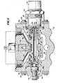
- the numeral 10 indicates a valve housing having a bore 12 therethrough. Reciprocally received within the bore 12 is a spool 14 equipped with four land areas 16, 18, 20, and 22. Between land areas 16 and 18 is a groove area 24, and between land areas 20 and 22 is a groove area 26. Land areas 18 and 20 are machined with close tolerances for reasons which will become apparent hereinafter.
- the valve housing 10 is machined with four internal grooves 28, 30, 32 and 34 located opposite the axial extremities of the land areas 18 and 20 when the spool 14 is in the position shown in Figure 2.
- Groove areas 24 and 26 communicate with a tank 36 (shown only in Figure 4) by way of a passageway 38 and a return port 40.
- Internal grooves 28 and 30 can communicate with a load 42 by way of passageway 44
- internal grooves 32 and 34 can communicate with the load 42 by way of a passageway 46.
- Passageways 44 and 46 are closed and opened by the movements of land areas 18 and 20, respectively; in the location of the spool 14 shown in Figure 2, both passageways are closed.
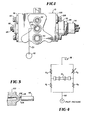
- a pressure groove 48 which communicates via passage 51 with a port 50 shown in Figure 1.
- the port 50 is connected to the output of a pump 52, so that pressure from the pump 52 is communicated to the pressure groove 48 and can then be communicated to either passageway 44 or passageway 46, depending on the position of spool 14.
- pressure from the pressure groove 48 is communicated to neither passageway.
- pressurized fluid will flow to the load 42 through internal groove 30 and passageway 44 and return to tank 36 via passageway 46 and internal groove 34.
- pressurized fluid will flow to the load 42 through internal groove 32 and passageway 46 and return to tank 36 via passageway 44 and internal groove 28.
- a chamber 54 closed by an end gland 56 retained in position on the valve housing 10 by clips 58 and bolts 60.
- End gland 56 receives a piston 62, a screw 64, a jam nut 66, and a centering spring 68.
- a chamber 70 which receives a second centering spring 72 and which is closed by apparatus described hereinafter.
- the piston 62, the screw 64, the jam nut 66 and the two centering springs 68 and 72 collectively serve as a mechanical "null" adjustment for the spool 14. That is, by adjusting screw 64 it is possible to initially locate land areas 18 and 20 on the spool 14 so that the internal grooves 28 and 30 align with land 18 and grooves 32 and 34 align with land 20 of spool 14.
- Chambers 54 and 70 are subjected to intermediate control pressures by means of orifices 74 (A 1 ) and 76 (A z ), which communicate with the chambers 54 and 70 via the conduits 78 and 80, respectively.
- the orifices 74 and 76 are of fixed dimensions and are equal to each other.
- An isolated pilot port 82 which serves as a source of isolated pilot pressure, communicates with the orifices 74 and 76 via an internal filter 84 which protects those orifices from fluid contamination.
- conduit 86 communicates at its right end with the groove area 26 via a hole 88 in the spool 14 and at its left end with the chamber 54 via a third fixed orifice 90 (A3) which is equal to orifice 74 (A 1 ) and orifice 76 (A z ).
- a force motor 94 Attached to the right end of valve housing 10, as seen in Figure 2, by means of a mounting cap 92 is a force motor 94 having a force motor stem 96 terminating in a planar end 98 which extends toward the right end of the spool 14.
- the end of the spool 14 which faces the force motor 94 carries a pressed-in nozzle 100 having a planar annular surface 102 disposed opposite and parallel to the planar end 98 of the force motor stem 96.
- the area between the planar end 98 of the force motor stem 96 and the planar annular surface 102 on the nozzle 100 constitutes a fourth orifice 104 (A4), which, as explained hereinafter, is of variable area.
- the force motor 94 preferably includes a built-in bias spring to overcome any force built up on the force motor stem 96 due to the pressure at the nozzle 100 opening.
- Mounting cap 92 is retained in position on the valve housing 10 by clips 106 and bolts 108. At the left end of mounting cap 94 is a flat washer 110 which abuts the centering spring and which limits the travel of the spool 14 in the right-hand direction.
- the force motor 94 is mounted in the mounting cap 92 by threads 112 and retained for locking purposes by locking ring 114. This arrangement allows external adjustment of the force motor stem 96, which in turn permits external manual adjustment of the variable orifice 104 (A4).
- the force motor 94 is adjusted so that the variable orifice 104 (A4) equals the fixed orifices 74 (A,), 76 (A 2 ), and 90 (A3) in effective area.
- the pressures in each of the chambers 54 and 70 is exactly half the pilot supply pressure applied to pilot port 82. Since the pressures in the chambers 54 and 70 are equal to each other, the spool 14 is held stationary, which is called the "null" of the valve.
- the spool 14 will move only that amount necessary to re-establish the force balance.
- the spool 14 is held in the newly attained position. If the input to the force motor 94 is later varied, the spool 14 will quickly move to a new position re-establishing the force balance. In particular, if the input to the force motor 94 later ceases, the spool 14 will return to the "null" of the valve. Similarly, lack of controlling pressures in the chambers 54 and 70 caused, for instance, by failure of the pump 52 (if the isolated pilot pressure is derived from the pump 52) will cause the spool 14 to return to its "null" position.
- control pressure bridge is displayed schematically in Figure 4.
- the subject invention provides a pilot pressure bridge arrangement in which there are four orifices, only one of which is variable. An automatic feedback is thus developed which provides accurate, continuous control.
Landscapes
- Engineering & Computer Science (AREA)
- Physics & Mathematics (AREA)
- Fluid Mechanics (AREA)
- Mechanical Engineering (AREA)
- General Engineering & Computer Science (AREA)
- Servomotors (AREA)
Claims (20)
dadurch gekennzeichnet, daß:
Applications Claiming Priority (2)
| Application Number | Priority Date | Filing Date | Title |
|---|---|---|---|
| US81546777A | 1977-07-13 | 1977-07-13 | |
| US815467 | 1977-07-13 |
Publications (2)
| Publication Number | Publication Date |
|---|---|
| EP0000445A1 EP0000445A1 (de) | 1979-01-24 |
| EP0000445B1 true EP0000445B1 (de) | 1982-11-24 |
Family
ID=25217875
Family Applications (1)
| Application Number | Title | Priority Date | Filing Date |
|---|---|---|---|
| EP19780300136 Expired EP0000445B1 (de) | 1977-07-13 | 1978-07-10 | Servoventil |
Country Status (4)
| Country | Link |
|---|---|
| EP (1) | EP0000445B1 (de) |
| JP (2) | JPS5420275A (de) |
| CA (1) | CA1093426A (de) |
| DE (1) | DE2862092D1 (de) |
Families Citing this family (3)
| Publication number | Priority date | Publication date | Assignee | Title |
|---|---|---|---|---|
| DE3216692A1 (de) * | 1982-05-05 | 1983-11-10 | Kienzle Apparate Gmbh, 7730 Villingen-Schwenningen | Elektropneumatisches servoventil |
| JPS60118075U (ja) * | 1984-01-18 | 1985-08-09 | 株式会社トキメック | 比例ソレノイド形スプ−ル弁 |
| WO2020002472A1 (en) | 2018-06-28 | 2020-01-02 | Basf Se | Use of alkynylthiophenes as nitrification inhibitors |
Family Cites Families (7)
| Publication number | Priority date | Publication date | Assignee | Title |
|---|---|---|---|---|
| US2972999A (en) * | 1955-11-01 | 1961-02-28 | Sanders Associates Inc | Two-stage, differential, hydraulic servo valve |
| US2973746A (en) * | 1957-06-03 | 1961-03-07 | Edward C Jupa | Hydraulic servo valve |
| US2977985A (en) * | 1958-12-29 | 1961-04-04 | Pegasus Lab Inc | Electro-hydraulic servo control valve |
| US3012579A (en) * | 1959-06-08 | 1961-12-12 | Pneumo Dynamics Corp | Electrohydraulic servo valve |
| GB1268767A (en) * | 1968-06-26 | 1972-03-29 | Dowty Technical Dev Ltd | Electro-hydraulic and electro-pneumatic servo valves |
| JPS5421912B2 (de) * | 1971-12-02 | 1979-08-02 | ||
| US3799202A (en) * | 1972-11-29 | 1974-03-26 | Sperry Rand Corp | Power transmission |
-
1978
- 1978-07-10 EP EP19780300136 patent/EP0000445B1/de not_active Expired
- 1978-07-10 DE DE7878300136T patent/DE2862092D1/de not_active Expired
- 1978-07-12 CA CA307,244A patent/CA1093426A/en not_active Expired
- 1978-07-13 JP JP8464178A patent/JPS5420275A/ja active Pending
-
1985
- 1985-12-09 JP JP18852185U patent/JPS61116205U/ja active Pending
Also Published As
| Publication number | Publication date |
|---|---|
| EP0000445A1 (de) | 1979-01-24 |
| JPS5420275A (en) | 1979-02-15 |
| JPS61116205U (de) | 1986-07-22 |
| DE2862092D1 (en) | 1982-12-30 |
| CA1093426A (en) | 1981-01-13 |
Similar Documents
| Publication | Publication Date | Title |
|---|---|---|
| KR100292544B1 (ko) | 파일럿솔레노이드제어밸브및이를이용한유압식제어장치 | |
| US4643225A (en) | Pressure regulating valve | |
| EP1186784B1 (de) | Nach beiden RIchtungen vorgesteuerte Ventilanordnung | |
| EP0151174B1 (de) | Dreiweg-proportionalventil | |
| EP0066150B1 (de) | Servogesteuertes Wegeventil mit variabeler Verstärkung | |
| US4313468A (en) | Servo valve | |
| EP0953776B1 (de) | Elektromagnetisch betätigte Ventileinheit mit zwei Kolbenschiebern | |
| US6073652A (en) | Pilot solenoid control valve with integral pressure sensing transducer | |
| US4227443A (en) | Fail-fixed servovalve | |
| US4598626A (en) | Feedback controlled hydraulic valve system | |
| US5735122A (en) | Actuator with failfixed zero drift | |
| JPH0364744B2 (de) | ||
| US5038671A (en) | Control valve | |
| EP0607903B1 (de) | Stromventil mit Vorsteuerung und Druckkompensation | |
| US5156189A (en) | High flow control valve | |
| US6192928B1 (en) | Valve assembly | |
| US4589437A (en) | Reel speed valve assembly | |
| EP0110501B1 (de) | Redundant gesteuertes Stellsystem für ein direkt angetriebenes konzentrisches Ventil | |
| US4212323A (en) | Power assist proportional remote controller | |
| EP0000445B1 (de) | Servoventil | |
| US4085920A (en) | Pilot control valve with servo means | |
| US3587617A (en) | Fluid control apparatus | |
| EP3875783A1 (de) | Servoventil | |
| US4479514A (en) | Float positioning assembly for pilot operated valve | |
| EP0311746B1 (de) | Regelungsanordnung für ein Servosystem |
Legal Events
| Date | Code | Title | Description |
|---|---|---|---|
| PUAI | Public reference made under article 153(3) epc to a published international application that has entered the european phase |
Free format text: ORIGINAL CODE: 0009012 |
|
| AK | Designated contracting states |
Designated state(s): DE FR GB SE |
|
| 17P | Request for examination filed | ||
| GRAA | (expected) grant |
Free format text: ORIGINAL CODE: 0009210 |
|
| AK | Designated contracting states |
Designated state(s): DE FR GB SE |
|
| PG25 | Lapsed in a contracting state [announced via postgrant information from national office to epo] |
Ref country code: SE Effective date: 19821124 |
|
| REF | Corresponds to: |
Ref document number: 2862092 Country of ref document: DE Date of ref document: 19821230 |
|
| ET | Fr: translation filed | ||
| RAP2 | Party data changed (patent owner data changed or rights of a patent transferred) |
Owner name: DYNEX/RIVETT INC. |
|
| PGFP | Annual fee paid to national office [announced via postgrant information from national office to epo] |
Ref country code: GB Payment date: 19910709 Year of fee payment: 14 |
|
| PGFP | Annual fee paid to national office [announced via postgrant information from national office to epo] |
Ref country code: DE Payment date: 19910723 Year of fee payment: 14 |
|
| PGFP | Annual fee paid to national office [announced via postgrant information from national office to epo] |
Ref country code: FR Payment date: 19910731 Year of fee payment: 14 |
|
| PG25 | Lapsed in a contracting state [announced via postgrant information from national office to epo] |
Ref country code: GB Effective date: 19920710 |
|
| GBPC | Gb: european patent ceased through non-payment of renewal fee |
Effective date: 19920710 |
|
| PG25 | Lapsed in a contracting state [announced via postgrant information from national office to epo] |
Ref country code: FR Effective date: 19930331 |
|
| PG25 | Lapsed in a contracting state [announced via postgrant information from national office to epo] |
Ref country code: DE Effective date: 19930401 |
|
| REG | Reference to a national code |
Ref country code: FR Ref legal event code: ST |
|
| PLBE | No opposition filed within time limit |
Free format text: ORIGINAL CODE: 0009261 |
|
| STAA | Information on the status of an ep patent application or granted ep patent |
Free format text: STATUS: NO OPPOSITION FILED WITHIN TIME LIMIT |