EP0940868B1 - Fuel cell stack - Google Patents
Fuel cell stack Download PDFInfo
- Publication number
- EP0940868B1 EP0940868B1 EP99301562A EP99301562A EP0940868B1 EP 0940868 B1 EP0940868 B1 EP 0940868B1 EP 99301562 A EP99301562 A EP 99301562A EP 99301562 A EP99301562 A EP 99301562A EP 0940868 B1 EP0940868 B1 EP 0940868B1
- Authority
- EP
- European Patent Office
- Prior art keywords
- gas
- flow passage
- gas flow
- fuel cell
- grooves
- Prior art date
- Legal status (The legal status is an assumption and is not a legal conclusion. Google has not performed a legal analysis and makes no representation as to the accuracy of the status listed.)
- Expired - Lifetime
Links
- 239000000446 fuel Substances 0.000 title claims description 64
- 239000007789 gas Substances 0.000 claims description 248
- 239000002737 fuel gas Substances 0.000 claims description 44
- QVGXLLKOCUKJST-UHFFFAOYSA-N atomic oxygen Chemical compound [O] QVGXLLKOCUKJST-UHFFFAOYSA-N 0.000 claims description 34
- 239000001301 oxygen Substances 0.000 claims description 34
- 229910052760 oxygen Inorganic materials 0.000 claims description 34
- 230000003247 decreasing effect Effects 0.000 claims description 26
- 230000005484 gravity Effects 0.000 claims description 6
- 239000005518 polymer electrolyte Substances 0.000 claims description 6
- 239000007787 solid Substances 0.000 claims description 4
- 238000009792 diffusion process Methods 0.000 description 12
- UFHFLCQGNIYNRP-UHFFFAOYSA-N Hydrogen Chemical compound [H][H] UFHFLCQGNIYNRP-UHFFFAOYSA-N 0.000 description 11
- 230000007423 decrease Effects 0.000 description 9
- 238000007599 discharging Methods 0.000 description 8
- 239000000203 mixture Substances 0.000 description 7
- 230000000694 effects Effects 0.000 description 5
- XLYOFNOQVPJJNP-UHFFFAOYSA-N water Substances O XLYOFNOQVPJJNP-UHFFFAOYSA-N 0.000 description 5
- MYMOFIZGZYHOMD-UHFFFAOYSA-N Dioxygen Chemical compound O=O MYMOFIZGZYHOMD-UHFFFAOYSA-N 0.000 description 4
- 239000000498 cooling water Substances 0.000 description 4
- 229910001882 dioxygen Inorganic materials 0.000 description 4
- WYTGDNHDOZPMIW-RCBQFDQVSA-N alstonine Natural products C1=CC2=C3C=CC=CC3=NC2=C2N1C[C@H]1[C@H](C)OC=C(C(=O)OC)[C@H]1C2 WYTGDNHDOZPMIW-RCBQFDQVSA-N 0.000 description 3
- 239000003054 catalyst Substances 0.000 description 3
- 239000003792 electrolyte Substances 0.000 description 3
- GPRLSGONYQIRFK-UHFFFAOYSA-N hydron Chemical compound [H+] GPRLSGONYQIRFK-UHFFFAOYSA-N 0.000 description 3
- 238000000034 method Methods 0.000 description 3
- 238000011144 upstream manufacturing Methods 0.000 description 3
- OKTJSMMVPCPJKN-UHFFFAOYSA-N Carbon Chemical compound [C] OKTJSMMVPCPJKN-UHFFFAOYSA-N 0.000 description 2
- NBIIXXVUZAFLBC-UHFFFAOYSA-N Phosphoric acid Chemical compound OP(O)(O)=O NBIIXXVUZAFLBC-UHFFFAOYSA-N 0.000 description 2
- 230000001133 acceleration Effects 0.000 description 2
- 229910052799 carbon Inorganic materials 0.000 description 2
- 238000004891 communication Methods 0.000 description 2
- 239000001257 hydrogen Substances 0.000 description 2
- 229910052739 hydrogen Inorganic materials 0.000 description 2
- 238000003754 machining Methods 0.000 description 2
- 239000012528 membrane Substances 0.000 description 2
- 229910000147 aluminium phosphate Inorganic materials 0.000 description 1
- 230000009286 beneficial effect Effects 0.000 description 1
- 238000005341 cation exchange Methods 0.000 description 1
- 238000005520 cutting process Methods 0.000 description 1
- 238000001514 detection method Methods 0.000 description 1
- -1 for example Substances 0.000 description 1
- 150000002431 hydrogen Chemical class 0.000 description 1
- 239000007788 liquid Substances 0.000 description 1
- 238000004519 manufacturing process Methods 0.000 description 1
Images


Classifications
-
- H—ELECTRICITY
- H01—ELECTRIC ELEMENTS
- H01M—PROCESSES OR MEANS, e.g. BATTERIES, FOR THE DIRECT CONVERSION OF CHEMICAL ENERGY INTO ELECTRICAL ENERGY
- H01M8/00—Fuel cells; Manufacture thereof
- H01M8/02—Details
- H01M8/0202—Collectors; Separators, e.g. bipolar separators; Interconnectors
- H01M8/0258—Collectors; Separators, e.g. bipolar separators; Interconnectors characterised by the configuration of channels, e.g. by the flow field of the reactant or coolant
- H01M8/0263—Collectors; Separators, e.g. bipolar separators; Interconnectors characterised by the configuration of channels, e.g. by the flow field of the reactant or coolant having meandering or serpentine paths
-
- H—ELECTRICITY
- H01—ELECTRIC ELEMENTS
- H01M—PROCESSES OR MEANS, e.g. BATTERIES, FOR THE DIRECT CONVERSION OF CHEMICAL ENERGY INTO ELECTRICAL ENERGY
- H01M8/00—Fuel cells; Manufacture thereof
- H01M8/02—Details
- H01M8/0202—Collectors; Separators, e.g. bipolar separators; Interconnectors
- H01M8/0258—Collectors; Separators, e.g. bipolar separators; Interconnectors characterised by the configuration of channels, e.g. by the flow field of the reactant or coolant
- H01M8/026—Collectors; Separators, e.g. bipolar separators; Interconnectors characterised by the configuration of channels, e.g. by the flow field of the reactant or coolant characterised by grooves, e.g. their pitch or depth
-
- H—ELECTRICITY
- H01—ELECTRIC ELEMENTS
- H01M—PROCESSES OR MEANS, e.g. BATTERIES, FOR THE DIRECT CONVERSION OF CHEMICAL ENERGY INTO ELECTRICAL ENERGY
- H01M8/00—Fuel cells; Manufacture thereof
- H01M8/02—Details
- H01M8/0202—Collectors; Separators, e.g. bipolar separators; Interconnectors
- H01M8/0267—Collectors; Separators, e.g. bipolar separators; Interconnectors having heating or cooling means, e.g. heaters or coolant flow channels
-
- H—ELECTRICITY
- H01—ELECTRIC ELEMENTS
- H01M—PROCESSES OR MEANS, e.g. BATTERIES, FOR THE DIRECT CONVERSION OF CHEMICAL ENERGY INTO ELECTRICAL ENERGY
- H01M8/00—Fuel cells; Manufacture thereof
- H01M8/24—Grouping of fuel cells, e.g. stacking of fuel cells
- H01M8/2457—Grouping of fuel cells, e.g. stacking of fuel cells with both reactants being gaseous or vaporised
-
- H—ELECTRICITY
- H01—ELECTRIC ELEMENTS
- H01M—PROCESSES OR MEANS, e.g. BATTERIES, FOR THE DIRECT CONVERSION OF CHEMICAL ENERGY INTO ELECTRICAL ENERGY
- H01M2300/00—Electrolytes
- H01M2300/0017—Non-aqueous electrolytes
- H01M2300/0065—Solid electrolytes
- H01M2300/0082—Organic polymers
-
- H—ELECTRICITY
- H01—ELECTRIC ELEMENTS
- H01M—PROCESSES OR MEANS, e.g. BATTERIES, FOR THE DIRECT CONVERSION OF CHEMICAL ENERGY INTO ELECTRICAL ENERGY
- H01M8/00—Fuel cells; Manufacture thereof
- H01M8/02—Details
- H01M8/0202—Collectors; Separators, e.g. bipolar separators; Interconnectors
- H01M8/0258—Collectors; Separators, e.g. bipolar separators; Interconnectors characterised by the configuration of channels, e.g. by the flow field of the reactant or coolant
- H01M8/0265—Collectors; Separators, e.g. bipolar separators; Interconnectors characterised by the configuration of channels, e.g. by the flow field of the reactant or coolant the reactant or coolant channels having varying cross sections
-
- Y—GENERAL TAGGING OF NEW TECHNOLOGICAL DEVELOPMENTS; GENERAL TAGGING OF CROSS-SECTIONAL TECHNOLOGIES SPANNING OVER SEVERAL SECTIONS OF THE IPC; TECHNICAL SUBJECTS COVERED BY FORMER USPC CROSS-REFERENCE ART COLLECTIONS [XRACs] AND DIGESTS
- Y02—TECHNOLOGIES OR APPLICATIONS FOR MITIGATION OR ADAPTATION AGAINST CLIMATE CHANGE
- Y02E—REDUCTION OF GREENHOUSE GAS [GHG] EMISSIONS, RELATED TO ENERGY GENERATION, TRANSMISSION OR DISTRIBUTION
- Y02E60/00—Enabling technologies; Technologies with a potential or indirect contribution to GHG emissions mitigation
- Y02E60/30—Hydrogen technology
- Y02E60/50—Fuel cells
Definitions
- the present invention relates to a fuel cell stack comprising a fuel cell unit including a solid polymer electrolyte interposed between an anode electrode and a cathode electrode, and first and second separators for holding the cell unit therebetween.
- a fuel cell of the solid polymer electrolyte type is known in the art which includes an anode electrode and a cathode electrode disposed opposingly on both sides of an electrolyte membrane composed of a polymer electrolyte (cation exchange membrane) to construct a fuel cell structure (hereinafter referred to as "fuel cell unit") which is held between separators.
- fuel cell unit a fuel cell structure
- a predetermined number of the fuel cell units are stacked to provide a fuel cell stack which is practically used.
- Such a fuel cell is operated as follows. That is, a fuel gas, for example, hydrogen, which is supplied to the anode electrode, is converted into hydrogen ion on electrode catalysts. The hydrogen ion is moved toward the cathode electrode via the polymer electrolyte which is appropriately humidified. Electrons are generated during this process, which are extracted by an external circuit to be utilized as direct current electric energy. An oxygen-containing gas, for example, oxygen gas or air is supplied to the cathode electrode. Therefore, the hydrogen ion, the electrons, and the oxygen are reacted with each other on the cathode electrode to produce water.
- a fuel gas for example, hydrogen
- anode electrode is converted into hydrogen ion on electrode catalysts.
- the hydrogen ion is moved toward the cathode electrode via the polymer electrolyte which is appropriately humidified. Electrons are generated during this process, which are extracted by an external circuit to be utilized as direct current electric energy.
- An oxygen-containing gas for example, oxygen gas or air is supplied to
- conductive porous layers such as porous carbon paper sheets are disposed on electrode catalyst layers (electrode surfaces), and they are interposed between the separators.
- One or a plurality of gas flow passages, each of which is designed to have a uniform widthwise dimension, are disposed on mutually opposing surfaces of the respective separators.
- the number of reactive molecules per unit area existing in the vicinity of an outlet of the gas flow passage decreases as compared with the number of reactive molecules per unit area existing at an inlet of the gas flow passage, because the fuel gas and the oxygen-containing gas supplied to the gas flow passage are consumed in the electrode surface. Accordingly, a problem occurs that the reaction in the electrode surface becomes non-uniform, and the cell performance becomes unstable.
- a fuel cell is known, as disclosed in Japanese Laid-Open Patent Publication No. 6-267564 .
- the fuel cell includes a fuel-delivering plate having a fuel flow passage for supplying fuel to an anode electrode, and an oxygen-containing gas-delivering plate having an oxygen-containing gas flow passage for supplying an oxygen-containing gas to a cathode electrode, in which at least any one of the depth or the width of the oxygen-containing gas flow passage of the oxygen-containing gas-delivering plate gradually decreases from an upstream flow passage region to a downstream flow passage region.
- the gas flow passage is provided in a serpentine manner or in an encircling manner in a surface of the separator. Therefore, the gas flow passage is considerably lengthy in the separator surface.
- the depth of the oxygen-containing gas flow passage is large in the upstream flow passage region, and hence the separator itself is considerably thick-walled. Accordingly, a problem is pointed out that it is not easy for the entire fuel cell to achieve a compact size. Further, a problem arises in that the machining operation for manufacturing the gas flow passage to have the depth which gradually decreases from the upstream to the downstream is extremely complicated.
- JP-A-5613/4473 teaches a fuel cell with a phosphoric acid electrolyte with electrodes and gas providing plates arranged on both sides. Each plate is provided with a number of gas flow passage grooves, decreasing in number from a gas inlet side to a gas outlet side.
- a principal object of the present invention is to provide a fuel cell stack which makes it possible to ensure good gas diffusion performance and good drainage performance, and effectively miniaturize the size of the fuel cell stack.
- the present invention provides a fuel cell stack as claimed in claim 1.
- FIG. 1 shows an exploded perspective view of principal parts of a fuel cell stack 10 according to a first embodiment of the present invention
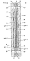
- FIG. 2 shows a schematic longitudinal sectional view of the fuel cell stack 10.
- the fuel cell stack 10 comprises a fuel cell unit 12, and first and second separators 14, 16 for holding the fuel cell unit 12 therebetween. A plurality of sets of the foregoing components are optionally stacked.
- the fuel cell unit 12 includes a solid polymer electrolyte 18, and an anode electrode 20 and a cathode electrode 22 arranged with the electrolyte 18 interposed therebetween.
- First and second gaskets 28, 30 are disposed on both sides of the fuel cell unit 12.
- the first gasket 28 has a large opening 32 for accommodating the anode electrode 20 and the first gas diffusion layer 24, while the second gasket 30 has a large opening 34 for accommodating the cathode electrode 22 and the second gas diffusion layer 26.
- the fuel cell unit 12 and the first and second gaskets 28, 30 are interposed between the first and second separators 14, 16.
- the first separator 14 is provided at its upper portion with an inlet hole 36a for allowing a fuel gas such as hydrogen to pass therethrough, an inlet hole 36b for allowing cooling water to pass therethrough, and an inlet hole 36c for allowing an oxygen-containing gas such as oxygen or air to pass therethrough.
- the first separator 14 is provided at its lower portion with an outlet hole 38a for allowing the fuel gas to pass therethrough, an outlet hole 38b for allowing the cooling water to pass therethrough, and an outlet hole 38c for allowing the oxygen-containing gas to pass therethrough.
- a fuel gas flow passage (first gas flow passage) 40 for making communication between the holes 36a, 38a is formed in a surface 14a which opposes the anode electrode 20 of the first separator 14.
- the number of grooves used for the fuel gas flow passage 40 on the side of the inlet hole 36a for introducing the gas is set to be larger than the number of grooves on the side of the outlet hole 38a for discharging the gas.
- the grooves on the side of the inlet hole 36a are gradually merged with each other as the grooves come to the side of the outlet hole 38a.
- the decreasing rate of the number of grooves of the fuel gas flow passage 40 is set to correspond to the gas utilization factor of the fuel gas (the gas utilization factor being herein referred to as a utilization factor of hydrogen gas with respect to the entire gas such as a reformed gas).
- compositions of the reformed gas are shown, for example, in Table 1.
- Table 1 Illustrative composition of reformed gas H 2 CO 2 N 2 (1) Stationary state (1) 60 % 23 % 17 % (2) Acceleration 43.40 % 21 % 35.60 % (3) Stationary state (2) 75 % 25 % -
- Table 5 Decreasing rate of number of grooves Number of grooves on inlet side Decrease in number of grooves Decreasing rate corresponding to gas utilization factor (A) 16 16 ⁇ 8 50 % (B) 16 16 ⁇ 8 ⁇ 4 75 % (C) 14 14 ⁇ 7 50 % (D) 14 14 ⁇ 7 ⁇ 4 71 % (E) 12 12 ⁇ 6 50 % (F) 12 12 ⁇ 6 ⁇ 3 75 % (G) 12 12 ⁇ 6 ⁇ 3 ⁇ 2 ⁇ 1 92 % (H) 10 10 ⁇ 5 50 % (I) 10 10 ⁇ 5 ⁇ 3 70 %
- the gas utilization factor is about 50 % as shown in Table 2.
- Those used for the decreasing rate of the number of grooves include the arrangements of (A), (C), (E), and (H) shown in Table 5.
- the gas utilization factor is about 30 to 40 % as shown in Table 3.
- the shape of grooves of the fuel gas flow passage 40 is set based on the gas utilization factor of not less than 50 %. Therefore, those used for the decreasing rate of the number of grooves include the arrangements of (A), (C), (E), and (H) shown in Table 5, in the same manner as the illustrative composition (1).
- the gas utilization factor is about 50 to 70 % as shown in Table 4. Therefore, when the gas utilization factor is set to be 50 %, the arrangements of (A), (C), (E), and (H) shown in Table 5 are used. When the gas utilization factor is set to be not less than 70 %, the arrangements of (B), (D), (F), (G), and (I) shown in Table 5 are used.
- the arrangement of (F) shown in Table 5 is used.
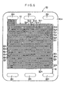
- the first gas flow passage grooves 42a to 42 l are formed in the surface of the surface 14a of the first separator 14 in a serpentine configuration vertically extending downwardly (in a direction indicated by an arrow A) while being separated from each other by a predetermined spacing distance.
- the number of the first gas flow passage grooves 42a to 42 l is decreased to a half at an approximately intermediate position of the height of the separator 14 to form six individual second gas flow passage grooves 44a to 44f.
- the second gas flow passage grooves 44a to 44f are serpentine in the direction indicated by the arrow A, and the number of them is decreased to a half at their terminals to form three individual third gas flow passage grooves 46a to 46c.
- the third gas flow passage grooves 46a to 46c are serpentine in the direction indicated by the arrow A, and then they communicate with the outlet hole 38a for discharging the gas.
- the first gas flow passage grooves 42a to 42 l are continuously merged to the third gas flow passage grooves 46a to 46c.
- the first gas flow passage grooves 42a to 42 l communicate with the inlet hole 36a for introducing the gas, while the third gas flow passage grooves 46a to 46c communicate with the outlet hole 38a for discharging the gas.
- the second separator 16 is provided at its upper portion with a fuel gas inlet hole 47a, a cooling water inlet hole 47b, and an oxygen-containing gas inlet hole 47c.
- the second separator 16 is provided at its lower portion with a fuel gas outlet hole 48a, a cooling water outlet hole 48b, and an oxygen-containing gas outlet hole 48c.
- an oxygen-containing gas flow passage (second gas flow passage) 50 for making communication between the holes 47a, 48c is formed on a surface 16a opposing the cathode electrode 22 of the second separator 16.
- the oxygen-containing gas flow passage 50 is constructed in the same manner as the fuel gas flow passage 40. Therefore, the same constitutive components are designated by the same reference numerals, and a detailed explanation of which will be omitted.
- the reformed gas as the fuel gas is supplied to the fuel cell stack 10, and the air as the oxygen-containing gas is supplied thereto.
- the reformed gas is introduced via the inlet hole 36a of the first separator 14 into the fuel gas flow passage 40.
- the reformed gas which has been supplied to the fuel gas flow passage 40, is initially introduced into the first gas flow passage grooves 42a to 42 l.
- the gas is moved downwardly in accordance with gravity (in the direction indicated by the arrow A) while following serpentine configuration along the surface 14a of the first separator 14.
- the hydrogen gas contained in the reformed gas passes through the first gas diffusion layer 24, and it is supplied to the anode electrode 20 of the fuel cell unit 12.
- the residual reformed gas is introduced into the second gas flow passage grooves 44a to 44f connected to the terminals of the first gas flow passage grooves 42a to 42 l.
- the gas is moved in the direction of gravity while following serpentine configuration along the surface 14a to effect diffusion of the hydrogen gas.
- the reformed gas is thereafter introduced into the third gas flow passage grooves 46a to 46c connected to the terminals of the second gas flow passage grooves 44a to 44f.
- the gas undergoes diffusion of the hydrogen gas while being moved in the direction of gravity. After that, the gas is discharged from the outlet hole 38a of the first separator 14.
- the number of grooves of the fuel gas flow passage 40 is decreased half by half in a stepwise manner from the inlet hole 36a for introducing the gas to the outlet hole 38a for discharging the gas. That is, the fuel gas flow passage 40 is provided with twelve of the first gas flow passage grooves 42a to 42 l, six of the second gas flow passage grooves 44a to 44f, and three of the third gas flow passage grooves 46a to 46c.
- the decreasing rate of the number of grooves is set to be 75 % corresponding to the gas utilization factor of the reformed gas.
- the gas flow rate can be improved at the outlet hole 38a for discharging the gas, because the fuel gas flow passage 40 is designed to decrease the number of grooves from the inlet hole 36a to the outlet hole 38a. Therefore, it is possible to increase the gas flow rate along the surface 14a of the first separator 14. Accordingly, an effect is obtained in that the gas diffusion performance is significantly improved by causing disturbance of the gas flow, and it is possible to improve the drainage performance. Therefore, the present invention is advantageous in that it is possible to certainly achieve an improvement in cell performance of the fuel cell stack 10.
- the fuel gas flow passage 40 is not changed in the depth direction in the first separator 14.
- the first separator 14 itself can be effectively thin-walled in its thickness. Accordingly, the entire fuel cell stack 10 can be easily miniaturized (thin-walled), and it is possible to simplify the machining operation.
- the air is supplied from the inlet hole 47c to the oxygen-containing gas flow passage 50 of the second separator 16.
- the air is supplied from the inlet hole 47c for introducing the gas to the outlet hole 48c for discharging the gas, in the same manner as the reformed gas is supplied to the fuel gas flow passage 40.
- the number of grooves of the oxygen-containing gas flow passage 50 is set to decrease half by half in a stepwise manner.
- the oxygen gas is supplied from the second gas diffusion layer 26 to the cathode electrode 22, while the number of reactive molecules per unit area is not decreased. Further, it is possible to increase the gas flow rate. Accordingly, a beneficial effect is obtained in that the cell performance is improved.
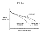
- FIG. 4 shows results of detection of characteristics of the current density and the voltage concerning the fuel cell stack 10 according to the first embodiment and two conventional fuel cells.
- the gas utilization factor of the reformed gas is 75 %, and the gas utilization factor of the oxygen-containing gas is 50 %.
- the reformed gas is humidified, while the oxygen-containing gas is not humidified.
- the applied pressure to the gas is set to be 100 Kpa for both the reformed gas and the oxygen-containing gas. Accordingly, the desired result is obtained in that the current density is high, and the cell performance is greatly improved in the fuel cell stack 10 according to the first embodiment as compared with the conventional fuel cells 1 and 2.
- both the fuel gas flow passage 40 and the oxygen-containing gas flow passage 50 are subjected to the decrease in the number of grooves from the gas inlet side to the gas outlet side.
- only one of the fuel gas flow passage 40 and the oxygen-containing gas flow passage 50 may be constructed as described above.
- the first and second separators 14, 16 are constructed such that the gas inlets are disposed at the upper portion, and the gas outlets are disposed at the lower portion so that the fuel gas and the oxygen-containing gas are allowed to flow from the upper portion to the lower portion.
- first and second separators constructed such that the gas inlets are disposed at the lower portion, and the gas outlets are disposed at the upper portion so that the fuel gas and the oxygen-containing gas are allowed to flow from the lower portion to the upper portion.
- the fuel gas flow passage and/or the oxygen-containing gas flow passage undergoes the decrease in the number of grooves from the gas inlet side to the gas outlet side, i.e., from the lower portion to the upper portion.
- FIG. 5 shows a front view of a first separator 60 included in a fuel cell stack according to a second embodiment of the present invention
- FIG. 6 shows a front view of a first separator 80 included in a fuel cell stack according to a third embodiment of the present invention.
- the same constitutive components as those of the first separator 14 included in the fuel cell stack 10 according to the first embodiment are designated by the same reference numerals, and a detailed explanation of which will be omitted.
- the first separator 60 has its surface 60a provided with a fuel gas flow passage 62.
- the fuel gas flow passage 62 corresponds to the gas utilization factor of 50 % shown in (H) in Table 5.
- ten individual gas flow passage grooves 61a to 64j communicate with an inlet hole 36a for introducing the gas.
- the first gas flow passage grooves 64a to 64j extend in a serpentine configuration in the direction of gravity, and they communicate with five individual second gas flow passage grooves 66a to 66e at their terminals.
- the second gas flow passage grooves 66a to 66e extend along the surface 60a while extending in a serpentine configuration in the direction of gravity, and they communicate with an outlet hole 38a for discharging the gas.
- a fuel gas flow passage 82 is provided in a surface 80a of a first separator 80 according to the third embodiment shown in FIG. 6 .
- the fuel gas flow passage 82 corresponds to the gas utilization factor of 92 % shown in (G) in Table 5. That is, the fuel gas flow passage 82 comprises twelve individual first gas flow passage grooves 84a to 84 l which communicate with an inlet hole 36a, six individual second gas flow passage grooves 86a to 86f which are connected to the terminals of the first gas flow passage grooves 84a to 84 l, three individual third gas flow passage grooves 88a to 88c which communicate with the terminals of the second gas flow passage grooves 86a to 86f, two individual fourth gas flow passage grooves 90a, 90b which communicate with the terminals of the third gas flow passage grooves 88a to 88c, and a fifth gas flow passage groove 92 which communicates with the terminals of the fourth gas flow passage grooves 90a, 90b.
- the fifth gas flow passage groove 92 communicates
- the fuel gas flow passage 82 is designed such that the number of grooves is decreased generally half by half in a stepwise manner from the inlet hole 36a to the outlet hole 38a.
- the number of grooves cannot be decreased to a half at the terminals of the third gas flow passage grooves 88a to 88c having the odd number of grooves.
- the fourth gas flow passage grooves 90, 90b are provided to have the number of a half of a number of grooves (four) obtained by adding 1 to the number of grooves 3 of the third gas flow passage grooves 88a to 88c, i.e., to have the number of two.
- the desired gas utilization factor can be established respectively by decreasing the number of grooves for the respective fuel gas flow passages 62, 82 from the inlet hole 36a for introducing the gas to the outlet hole 38a for discharging the gas. Accordingly, the same effect as that obtained in the first embodiment is obtained, for example, in that the number of reactive molecules per unit area can be maintained in the surfaces 60a, 80a of the first separators 60, 80 to cause the reaction to be uniform, and it is possible to improve the drainage performance and the gas diffusion performance.
- the groove width and the ridge width of the first separators 14, 60, 80 are set to be about 1 mm by means of, for example, a cutting processing. However, they may be set to have a dimension of not more than 1 mm.
- the number of grooves is easily changed and set depending on various factors such as the area of the separator. It is possible to use various combinations including, for example, eight individual grooves on the inlet side and two individual grooves on the outlet side, and twenty individual grooves on the inlet side and one individual groove on the outlet side. When the separator has a large area, the number of grooves on the inlet side can be set to be not less than twenty.
- the groove portions of the fuel gas flow passages 40, 62, 82 i.e., the portions to make contact with the reformed gas may be allowed to have a water-repelling property.
- the fuel cell stack according to the present invention is provided with the first and second gas flow passages for supplying the fuel gas and the oxygen-containing gas to the first and second separators which hold the fuel cell unit therebetween.
- the first gas flow passage and/or the second gas flow passage is set to have the number of gas flow passage grooves on the gas inlet side, which is larger than the number of gas flow passage grooves on the gas outlet side. Therefore, when the gas is consumed in the surface of the first separator and/or the second separator, the number of reactive molecules per unit area is prevented from being decreased by decreasing the number of gas flow passage grooves, making it possible to cause the reaction to be uniform on the electrode surface. Further, it is possible to effectively increase the gas flow rate on the gas outlet side, and it is possible to easily improve the drainage performance and the gas diffusion performance.
Landscapes
- Life Sciences & Earth Sciences (AREA)
- Engineering & Computer Science (AREA)
- Manufacturing & Machinery (AREA)
- Sustainable Development (AREA)
- Sustainable Energy (AREA)
- Chemical & Material Sciences (AREA)
- Chemical Kinetics & Catalysis (AREA)
- Electrochemistry (AREA)
- General Chemical & Material Sciences (AREA)
- Fuel Cell (AREA)
Applications Claiming Priority (2)
| Application Number | Priority Date | Filing Date | Title |
|---|---|---|---|
| JP04930498A JP4205774B2 (ja) | 1998-03-02 | 1998-03-02 | 燃料電池 |
| JP4930498 | 1998-03-02 |
Publications (3)
| Publication Number | Publication Date |
|---|---|
| EP0940868A2 EP0940868A2 (en) | 1999-09-08 |
| EP0940868A3 EP0940868A3 (en) | 2001-10-17 |
| EP0940868B1 true EP0940868B1 (en) | 2013-02-27 |
Family
ID=12827212
Family Applications (1)
| Application Number | Title | Priority Date | Filing Date |
|---|---|---|---|
| EP99301562A Expired - Lifetime EP0940868B1 (en) | 1998-03-02 | 1999-03-02 | Fuel cell stack |
Country Status (4)
| Country | Link |
|---|---|
| US (1) | US6048633A (enExample) |
| EP (1) | EP0940868B1 (enExample) |
| JP (1) | JP4205774B2 (enExample) |
| CA (1) | CA2251163C (enExample) |
Cited By (1)
| Publication number | Priority date | Publication date | Assignee | Title |
|---|---|---|---|---|
| WO2024042499A1 (en) * | 2022-08-26 | 2024-02-29 | Hydrogenics Corporation | Bipolar plates with variable furcation ratios |
Families Citing this family (72)
| Publication number | Priority date | Publication date | Assignee | Title |
|---|---|---|---|---|
| JP4523089B2 (ja) * | 1999-04-09 | 2010-08-11 | 本田技研工業株式会社 | 燃料電池スタック |
| JP4245091B2 (ja) * | 1998-10-01 | 2009-03-25 | 本田技研工業株式会社 | 燃料電池 |
| JP3530054B2 (ja) * | 1999-02-09 | 2004-05-24 | 本田技研工業株式会社 | 燃料電池 |
| US6420061B1 (en) * | 1999-02-23 | 2002-07-16 | Honda Giken Kogyo Kabushiki Kaisha | Fuel cell stack |
| US6613470B1 (en) * | 1999-09-01 | 2003-09-02 | Honda Giken Kogyo Kabushiki Kaisha | Solid polymer electrolyte fuel cell stack |
| US7226688B2 (en) | 1999-09-10 | 2007-06-05 | Honda Motor Co., Ltd. | Fuel cell |
| JP4809519B2 (ja) * | 1999-09-10 | 2011-11-09 | 本田技研工業株式会社 | 燃料電池 |
| US6383677B1 (en) | 1999-10-07 | 2002-05-07 | Allen Engineering Company, Inc. | Fuel cell current collector |
| US7527889B2 (en) * | 1999-10-19 | 2009-05-05 | Honda Giken Kogyo Kabushiki Kaisha | Fuel cell stack |
| AT407589B (de) * | 1999-11-03 | 2001-04-25 | Vaillant Gmbh | Brennstoffzelle |
| US6777126B1 (en) * | 1999-11-16 | 2004-08-17 | Gencell Corporation | Fuel cell bipolar separator plate and current collector assembly and method of manufacture |
| US6602626B1 (en) | 2000-02-16 | 2003-08-05 | Gencell Corporation | Fuel cell with internal thermally integrated autothermal reformer |
| JP2001250569A (ja) * | 2000-03-06 | 2001-09-14 | Toyota Motor Corp | 燃料電池及びその集電板 |
| AU2001245749A1 (en) | 2000-03-17 | 2001-10-03 | Allen Engineering Company, Inc. | Fuel cell stack assembly |
| JP4572441B2 (ja) * | 2000-04-10 | 2010-11-04 | トヨタ車体株式会社 | 燃料電池 |
| JP4651807B2 (ja) * | 2000-11-13 | 2011-03-16 | 本田技研工業株式会社 | 燃料電池 |
| US7968251B2 (en) | 2000-11-24 | 2011-06-28 | GM Global Technology Operations LLC | Electrical contact element and bipolar plate |
| CA2327962A1 (en) | 2000-12-11 | 2002-06-11 | Powerdisc Development Corp. Ltd. | Fuel cell stack |
| JP4598287B2 (ja) * | 2001-03-06 | 2010-12-15 | 本田技研工業株式会社 | 燃料電池スタックおよび燃料電池スタックの運転方法 |
| JP4967199B2 (ja) * | 2001-05-15 | 2012-07-04 | トヨタ自動車株式会社 | 燃料電池の配管構造 |
| JP4151314B2 (ja) * | 2001-06-18 | 2008-09-17 | トヨタ自動車株式会社 | 燃料電池 |
| DE10137847B4 (de) | 2001-08-02 | 2019-06-06 | General Motors Llc ( N. D. Ges. D. Staates Delaware ) | Verfahren zum Betrieb eines Brennstoffzellensystems, bei dem Temperaturen im Gefrierbereich von Wasser auftreten können sowie Brennstoffzellensystem |
| US6780536B2 (en) * | 2001-09-17 | 2004-08-24 | 3M Innovative Properties Company | Flow field |
| US20050064266A1 (en) * | 2001-09-18 | 2005-03-24 | Mohamed Abdou | Modular fuel cell cartridge and stack |
| JP3818149B2 (ja) * | 2001-12-21 | 2006-09-06 | 日産自動車株式会社 | 燃料電池 |
| JP3868810B2 (ja) * | 2001-12-27 | 2007-01-17 | 本田技研工業株式会社 | 燃料電池 |
| DE10304657B4 (de) | 2002-02-08 | 2015-07-02 | General Motors Llc ( N. D. Ges. D. Staates Delaware ) | Brennstoffzellenstapel sowie -system und Verfahren zum Betrieb eines Brennstoffzellensystems mit einem solchen Brennstoffzellenstapel |
| WO2003069706A2 (en) * | 2002-02-12 | 2003-08-21 | Symyx Technologies, Inc. | FUEL CELL ELECTROCATALYST OF Pt-Rh-Mo-Ni/Fe |
| US8021798B2 (en) * | 2002-03-06 | 2011-09-20 | Freeslate, Inc. | Fuel cell electrocatalyst of Pt-Zn-Ni/Fe |
| US20040023090A1 (en) * | 2002-03-30 | 2004-02-05 | Pearson Kenneth E. | Fuel cell system |
| US7087339B2 (en) | 2002-05-10 | 2006-08-08 | 3M Innovative Properties Company | Fuel cell membrane electrode assembly with sealing surfaces |
| JP4245308B2 (ja) * | 2002-05-16 | 2009-03-25 | 株式会社日本自動車部品総合研究所 | 燃料電池 |
| US7217471B2 (en) | 2002-05-17 | 2007-05-15 | 3M Innovative Properties Company | Membrane electrode assembly with compression control gasket |
| DE10230395A1 (de) * | 2002-07-05 | 2004-01-15 | General Motors Corp., Detroit | Leitfähiges Bauteil für elektrochemische Zellen sowie Verfahren zur Herstellung eines solchen Bauteils |
| WO2004038841A1 (ja) * | 2002-10-28 | 2004-05-06 | Honda Motor Co., Ltd. | 燃料電池 |
| JP3894109B2 (ja) * | 2002-11-28 | 2007-03-14 | トヨタ自動車株式会社 | 燃料電池 |
| US6772617B1 (en) | 2003-01-24 | 2004-08-10 | Gencell Corporation | Method and apparatus for in-situ leveling of progressively formed sheet metal |
| JP4522097B2 (ja) * | 2003-04-16 | 2010-08-11 | トヨタ自動車株式会社 | 燃料電池の制御方法 |
| JP4634933B2 (ja) | 2003-05-23 | 2011-02-16 | 本田技研工業株式会社 | 燃料電池 |
| US20070054802A1 (en) * | 2003-05-27 | 2007-03-08 | Symyx Technolgies, Inc. | Platinum-vanadium-iron fuel cell electrocatalyst |
| US7479343B2 (en) * | 2003-05-27 | 2009-01-20 | Symyx Technologies, Inc. | Platinum-indium-iron/tungsten/manganese fuel cell electrocatalyst |
| WO2005001967A1 (en) * | 2003-06-03 | 2005-01-06 | Symyx Technologies, Inc. | Platinum-chromium-copper/nickel fuel cell catalyst |
| JP4986616B2 (ja) * | 2003-06-06 | 2012-07-25 | サイミックス ソリューションズ, インコーポレイテッド | 燃料電池用触媒、担持電極触媒粉体、燃料電池電極、燃料電池電解質膜及び燃料電池並びに燃料電池内における電気化学的な変換方法 |
| WO2005024982A2 (en) * | 2003-08-18 | 2005-03-17 | Symyx Technologies, Inc. | Platinum-copper fuel cell catalyst |
| US20080166623A1 (en) * | 2003-09-03 | 2008-07-10 | Symyx Technologies, Inc. | Platinum-Nickel-Iron Fuel Cell Catalyst |
| JP5124900B2 (ja) * | 2003-11-06 | 2013-01-23 | トヨタ自動車株式会社 | スタック構造を有する燃料電池 |
| US20050221154A1 (en) * | 2004-04-01 | 2005-10-06 | Guthrie Robin J | Fuel cell reactant flow fields that maximize planform utilization |
| US7524575B2 (en) * | 2004-06-07 | 2009-04-28 | Hyteon Inc. | Flow field plate for use in fuel cells |
| US7531264B2 (en) * | 2004-06-07 | 2009-05-12 | Hyteon Inc. | Fuel cell stack with even distributing gas manifolds |
| US20060008695A1 (en) * | 2004-07-09 | 2006-01-12 | Dingrong Bai | Fuel cell with in-cell humidification |
| US7811965B2 (en) * | 2004-08-18 | 2010-10-12 | Symyx Solutions, Inc. | Platinum-copper-nickel fuel cell catalyst |
| KR100649204B1 (ko) | 2004-09-24 | 2006-11-24 | 삼성에스디아이 주식회사 | 연료 전지 시스템, 스택 및 세퍼레이터 |
| US7314680B2 (en) * | 2004-09-24 | 2008-01-01 | Hyteon Inc | Integrated fuel cell power module |
| JP5079994B2 (ja) * | 2004-11-25 | 2012-11-21 | 本田技研工業株式会社 | 燃料電池スタック |
| US7479333B2 (en) * | 2004-12-13 | 2009-01-20 | Hyteon, Inc. | Fuel cell stack with multiple groups of cells and flow passes |
| CA2594365C (en) * | 2005-01-05 | 2015-04-21 | Powerdisc Development Corporation Ltd. | Improved fuel cell cathode flow field |
| US7422994B2 (en) * | 2005-01-05 | 2008-09-09 | Symyx Technologies, Inc. | Platinum-copper-tungsten fuel cell catalyst |
| US20080044719A1 (en) * | 2005-02-02 | 2008-02-21 | Symyx Technologies, Inc. | Platinum-copper-titanium fuel cell catalyst |
| US20060188763A1 (en) * | 2005-02-22 | 2006-08-24 | Dingrong Bai | Fuel cell system comprising modular design features |
| US20060263663A1 (en) * | 2005-05-19 | 2006-11-23 | Fowler Sitima R | Temperature management of an end cell in a fuel cell stack |
| CN101248549B (zh) | 2005-08-05 | 2011-04-06 | 松下电器产业株式会社 | 燃料电池用隔板和燃料电池 |
| JP2007280933A (ja) * | 2006-03-16 | 2007-10-25 | Toyota Motor Corp | 燃料電池システム |
| CN101728553A (zh) * | 2006-06-21 | 2010-06-09 | 松下电器产业株式会社 | 燃料电池 |
| US7718298B2 (en) * | 2007-03-12 | 2010-05-18 | Gm Global Technology Operations, Inc. | Bifurcation of flow channels in bipolar plate flowfields |
| EP2224524B1 (en) * | 2009-02-12 | 2017-04-19 | Belenos Clean Power Holding AG | Fuel cell structure and separator plate for use therein |
| US8568941B2 (en) * | 2009-03-04 | 2013-10-29 | Panasonic Corporation | Fuel cell separator and fuel cell including same |
| DE112011105424T5 (de) | 2011-07-05 | 2014-04-03 | Toyota Jidosha Kabushiki Kaisha | Brennstoffzelle |
| US9644277B2 (en) | 2012-08-14 | 2017-05-09 | Loop Energy Inc. | Reactant flow channels for electrolyzer applications |
| WO2014026287A1 (en) | 2012-08-14 | 2014-02-20 | Powerdisc Development Corporation Ltd. | Fuel cell components, stacks and modular fuel cell systems |
| WO2014026288A1 (en) | 2012-08-14 | 2014-02-20 | Powerdisc Development Corporation Ltd. | Fuel cell flow channels and flow fields |
| JP7022073B2 (ja) | 2016-03-22 | 2022-02-17 | ループ エナジー インコーポレイテッド | 温度管理のための燃料電池の流れ場の設計 |
| JP7600867B2 (ja) * | 2021-05-27 | 2024-12-17 | トヨタ紡織株式会社 | 燃料電池用のセパレータ |
Family Cites Families (8)
| Publication number | Priority date | Publication date | Assignee | Title |
|---|---|---|---|---|
| JPS56134473A (en) * | 1980-03-25 | 1981-10-21 | Toshiba Corp | Unit cell for fuel cell |
| JPS57138782A (en) * | 1981-02-20 | 1982-08-27 | Hitachi Ltd | Fuel cell |
| JPS6276260A (ja) * | 1985-09-30 | 1987-04-08 | Ishikawajima Harima Heavy Ind Co Ltd | 燃料電池用セパレ−タ |
| JPS63195967A (ja) * | 1987-02-10 | 1988-08-15 | Toshiba Corp | 燃料電池 |
| US5300370A (en) * | 1992-11-13 | 1994-04-05 | Ballard Power Systems Inc. | Laminated fluid flow field assembly for electrochemical fuel cells |
| JP3553101B2 (ja) * | 1993-03-15 | 2004-08-11 | 三菱重工業株式会社 | 固体高分子電解質燃料電池 |
| US5686199A (en) * | 1996-05-07 | 1997-11-11 | Alliedsignal Inc. | Flow field plate for use in a proton exchange membrane fuel cell |
| JP3713912B2 (ja) * | 1996-08-08 | 2005-11-09 | アイシン精機株式会社 | 燃料電池のガス通路板 |
-
1998
- 1998-03-02 JP JP04930498A patent/JP4205774B2/ja not_active Expired - Lifetime
- 1998-10-26 CA CA002251163A patent/CA2251163C/en not_active Expired - Fee Related
- 1998-11-10 US US09/188,949 patent/US6048633A/en not_active Expired - Lifetime
-
1999
- 1999-03-02 EP EP99301562A patent/EP0940868B1/en not_active Expired - Lifetime
Cited By (1)
| Publication number | Priority date | Publication date | Assignee | Title |
|---|---|---|---|---|
| WO2024042499A1 (en) * | 2022-08-26 | 2024-02-29 | Hydrogenics Corporation | Bipolar plates with variable furcation ratios |
Also Published As
| Publication number | Publication date |
|---|---|
| CA2251163A1 (en) | 1999-09-02 |
| JPH11250923A (ja) | 1999-09-17 |
| US6048633A (en) | 2000-04-11 |
| EP0940868A2 (en) | 1999-09-08 |
| EP0940868A3 (en) | 2001-10-17 |
| CA2251163C (en) | 2002-05-28 |
| JP4205774B2 (ja) | 2009-01-07 |
Similar Documents
| Publication | Publication Date | Title |
|---|---|---|
| EP0940868B1 (en) | Fuel cell stack | |
| US6350540B1 (en) | Fuel cell with gas diffusion layer flow passage | |
| EP1239530B1 (en) | Solid polymer electrolyte fuel cell assembly, fuel cell stack, and method of supplying reaction gas in the fuel cell assembly | |
| EP0778631B1 (en) | Direct methanol type fuel cell | |
| EP0807323B2 (en) | Edge manifold assembly for an electrochemical fuel cell stack | |
| US5300370A (en) | Laminated fluid flow field assembly for electrochemical fuel cells | |
| US5521018A (en) | Embossed fluid flow field plate for electrochemical fuel cells | |
| US7867666B2 (en) | Fuel cell with triangular buffers for reactant gas and coolant | |
| CN101335358B (zh) | 燃料电池 | |
| MXPA04004279A (es) | Placas de campo de flujo de fluido para celulas energeticas. | |
| US6420061B1 (en) | Fuel cell stack | |
| JPH04355061A (ja) | 燃料電池 | |
| CA2403342C (en) | Fuel cell stack | |
| US7951508B2 (en) | Fuel cell | |
| WO1995028010A1 (en) | Electrochemical fuel cell stack with compact, centrally disposed compression mechanism | |
| JPS6160548B2 (enExample) | ||
| JP4185734B2 (ja) | 燃料電池スタック | |
| CA2403143C (en) | Fuel cell stack | |
| JP2004171824A (ja) | 燃料電池 | |
| JP3914418B2 (ja) | 燃料電池スタック | |
| JP4130889B2 (ja) | 燃料電池 | |
| JP2005183141A (ja) | 燃料電池 | |
| WO2004070859A1 (en) | Pem fuel cell with flow-field having a branched midsection | |
| JP2004014299A (ja) | 燃料電池 | |
| JP2021125438A (ja) | 燃料電池用セパレータ |
Legal Events
| Date | Code | Title | Description |
|---|---|---|---|
| PUAI | Public reference made under article 153(3) epc to a published international application that has entered the european phase |
Free format text: ORIGINAL CODE: 0009012 |
|
| AK | Designated contracting states |
Kind code of ref document: A2 Designated state(s): AT BE CH CY DE DK ES FI FR GB GR IE IT LI LU MC NL PT SE Kind code of ref document: A2 Designated state(s): DE FR GB |
|
| AX | Request for extension of the european patent |
Free format text: AL;LT;LV;MK;RO;SI |
|
| PUAL | Search report despatched |
Free format text: ORIGINAL CODE: 0009013 |
|
| AK | Designated contracting states |
Kind code of ref document: A3 Designated state(s): AT BE CH CY DE DK ES FI FR GB GR IE IT LI LU MC NL PT SE |
|
| AX | Request for extension of the european patent |
Free format text: AL;LT;LV;MK;RO;SI |
|
| 17P | Request for examination filed |
Effective date: 20020320 |
|
| AKX | Designation fees paid |
Free format text: AT BE CH LI |
|
| RBV | Designated contracting states (corrected) |
Designated state(s): DE FR GB |
|
| REG | Reference to a national code |
Ref country code: DE Ref legal event code: 8566 |
|
| 17Q | First examination report despatched |
Effective date: 20060216 |
|
| RIC1 | Information provided on ipc code assigned before grant |
Ipc: H01M 8/24 20060101AFI20120822BHEP Ipc: H01M 8/02 20060101ALI20120822BHEP |
|
| GRAP | Despatch of communication of intention to grant a patent |
Free format text: ORIGINAL CODE: EPIDOSNIGR1 |
|
| GRAS | Grant fee paid |
Free format text: ORIGINAL CODE: EPIDOSNIGR3 |
|
| GRAA | (expected) grant |
Free format text: ORIGINAL CODE: 0009210 |
|
| RIN1 | Information on inventor provided before grant (corrected) |
Inventor name: OKAMOTO, TAKAFUMI Inventor name: FUJII, YOSUKE Inventor name: ONO, HIDEMITSU Inventor name: SUGITA, NARUTOSHI Inventor name: YAMAMOTO, AKIO Inventor name: TANAKA, MANABU |
|
| AK | Designated contracting states |
Kind code of ref document: B1 Designated state(s): DE FR GB |
|
| REG | Reference to a national code |
Ref country code: GB Ref legal event code: FG4D |
|
| REG | Reference to a national code |
Ref country code: DE Ref legal event code: R096 Ref document number: 69944634 Country of ref document: DE Effective date: 20130425 |
|
| PGFP | Annual fee paid to national office [announced via postgrant information from national office to epo] |
Ref country code: FR Payment date: 20130325 Year of fee payment: 15 |
|
| PLBE | No opposition filed within time limit |
Free format text: ORIGINAL CODE: 0009261 |
|
| STAA | Information on the status of an ep patent application or granted ep patent |
Free format text: STATUS: NO OPPOSITION FILED WITHIN TIME LIMIT |
|
| 26N | No opposition filed |
Effective date: 20131128 |
|
| REG | Reference to a national code |
Ref country code: DE Ref legal event code: R097 Ref document number: 69944634 Country of ref document: DE Effective date: 20131128 |
|
| PGFP | Annual fee paid to national office [announced via postgrant information from national office to epo] |
Ref country code: GB Payment date: 20140226 Year of fee payment: 16 |
|
| REG | Reference to a national code |
Ref country code: DE Ref legal event code: R084 Ref document number: 69944634 Country of ref document: DE |
|
| REG | Reference to a national code |
Ref country code: FR Ref legal event code: ST Effective date: 20141128 |
|
| REG | Reference to a national code |
Ref country code: DE Ref legal event code: R084 Ref document number: 69944634 Country of ref document: DE Effective date: 20141120 |
|
| PG25 | Lapsed in a contracting state [announced via postgrant information from national office to epo] |
Ref country code: FR Free format text: LAPSE BECAUSE OF NON-PAYMENT OF DUE FEES Effective date: 20140331 |
|
| GBPC | Gb: european patent ceased through non-payment of renewal fee |
Effective date: 20150302 |
|
| PG25 | Lapsed in a contracting state [announced via postgrant information from national office to epo] |
Ref country code: GB Free format text: LAPSE BECAUSE OF NON-PAYMENT OF DUE FEES Effective date: 20150302 |
|
| PGFP | Annual fee paid to national office [announced via postgrant information from national office to epo] |
Ref country code: DE Payment date: 20160223 Year of fee payment: 18 |
|
| REG | Reference to a national code |
Ref country code: DE Ref legal event code: R119 Ref document number: 69944634 Country of ref document: DE |
|
| PG25 | Lapsed in a contracting state [announced via postgrant information from national office to epo] |
Ref country code: DE Free format text: LAPSE BECAUSE OF NON-PAYMENT OF DUE FEES Effective date: 20171003 |