EP0940657B1 - Luftdurchflussmesser - Google Patents
Luftdurchflussmesser Download PDFInfo
- Publication number
- EP0940657B1 EP0940657B1 EP99104503.0A EP99104503A EP0940657B1 EP 0940657 B1 EP0940657 B1 EP 0940657B1 EP 99104503 A EP99104503 A EP 99104503A EP 0940657 B1 EP0940657 B1 EP 0940657B1
- Authority
- EP
- European Patent Office
- Prior art keywords
- air flow
- passage
- downstream
- air
- bypass
- Prior art date
- Legal status (The legal status is an assumption and is not a legal conclusion. Google has not performed a legal analysis and makes no representation as to the accuracy of the status listed.)
- Expired - Lifetime
Links
Images


Classifications
-
- G—PHYSICS
- G01—MEASURING; TESTING
- G01F—MEASURING VOLUME, VOLUME FLOW, MASS FLOW OR LIQUID LEVEL; METERING BY VOLUME
- G01F5/00—Measuring a proportion of the volume flow
-
- G—PHYSICS
- G01—MEASURING; TESTING
- G01F—MEASURING VOLUME, VOLUME FLOW, MASS FLOW OR LIQUID LEVEL; METERING BY VOLUME
- G01F1/00—Measuring the volume flow or mass flow of fluid or fluent solid material wherein the fluid passes through a meter in a continuous flow
- G01F1/68—Measuring the volume flow or mass flow of fluid or fluent solid material wherein the fluid passes through a meter in a continuous flow by using thermal effects
- G01F1/684—Structural arrangements; Mounting of elements, e.g. in relation to fluid flow
- G01F1/6842—Structural arrangements; Mounting of elements, e.g. in relation to fluid flow with means for influencing the fluid flow
Definitions
- the present invention relates to an air flow meter for measuring air flow amount in an air flow passage.
- air flow meters having a sensor unit disposed in an air flow passage of an internal combustion engine are well known. These air flow meters measure intake air flow amount of the engine by the sensor unit so that amount of fuel supplied to the engine is controlled with high accuracy.
- thermal air flow meter having an exothermic resistor and a temperature sensing resistor as the sensor unit has nonlinear characteristics in which heat radiation amount of the resistors is in proportion to a square root of air flow velocity. Therefore, the thermal air flow meter may detect an air flow velocity smaller than an actual value due to response delay of the resistors.
- JP-B2-6-17810 , JP-A-8-193863 and JP-A-9-43020 disclose an air flow meter which has a bypass passage formed in an air flow passage to measure air flow amount in the main air flow passage by measuring air flow amount in the bypass passage through a sensor unit disposed in the bypass passage.
- pulsation in the bypass passage can be decreased and measurement accuracy of air flow amount can be improved by adjusting a ratio of a length of the bypass passage to a length between an inlet and an outlet of the bypass passage in an air flow direction in the air flow passage.
- air flowing through the bypass passage and air flowing through the air flow passage collide with each other in a joint portion between the bypass passage and the air flow passage, thereby decreasing air flow velocity in the bypass passage and generating turbulence in the bypass passage.
- air flow amount of the air flow passage may not be measured accurately.
- Document EP-A-0803712 discloses an air flow meter for measuring air flow amount in an air flow passage. That air flow meter comprises a bypass member disposed in that air flow passage for forming a bypass passage into which air flowing through that air flow passage partially flows. Further, a sensor unit disposed in said bypass passage for detecting the air flow amount in said bypass passage is provided wherein the bypass passage includes a down stream passage and an outflow port being surrounded at three sides by a surface disposed at an upstream air side of that air flow passage and opposing surfaces facing each other in a direction perpendicular to an airflow direction in that air flow passage and to an air flow direction in said downstream passage, said outflow port being opened in said air flow direction in said air flow passage and in said air flow direction in said down stream passage.
- an improved outlet is provided with the effect that turbulences will be avoided as air exits the measuring body. This is achieved by kneeping the downstream wall shorter than the partition wall to create a larger outlet which provides a smoother exit of the air.
- the air flow meter has the bypass passage formed into U-shape. Therefore, air flowing from the air flow passage into the bypass passage collides with an inner wall of a bypass member before colliding with a sensor unit. As a result, adhesive foreign matters adhere to the inner wall to be removed from air. Therefore, the foreign matters flowing through the air flow passage are restricted from directly colliding with the sensor unit and adhering thereto, thereby restricting performance of the sensor unit from declining.
- pulsation generated in the bypass passage can be decreased by setting a ratio (L1/L2) of a passage length L1 of the bypass passage to a length L2 between an inlet and an outlet of the bypass passage in an air flow direction in the air flow passage to be 4.0 ⁇ L1/L2 ⁇ 5.8. Further, when L1/L2 ⁇ 5.8, the bypass passage length L1 can be shortened to be less than a predetermined value. That is, since a passage length of the downstream passage of the U-shaped bypass passage can be decreased under a predetermined value, air flowing from the upstream passage to the downstream passage while changing its flow direction and discharged from the bypass passage includes air flowing in the air flow direction in the air flow passage. As a result, air being discharged from the bypass passage does not join the main air flow directly and perpendicularly, but joins the main air flow smoothly, thereby increasing air flow velocity in the bypass passage.
- the air flow meter has a venturi passage which draws air flowing through the bypass passage so that air flow velocity in the bypass passage is increased. As a result, air flow amount can be measured with high accuracy.
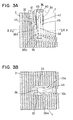
- FIGS. 1 , 2 show an air flow meter according to a first embodiment of the present invention.
- An air flow meter 10 shown in FIGS. 1 , 2 is disposed in, for example, an intake pipe of an internal combustion engine, and measures air flow amount of air flowing through an air flow passage formed by the intake pipe to be supplied to the engine.
- the air flow meter 10 comprises a circuit module 20 for measuring air flow amount and a bypass member 30.
- the circuit module 20 and the bypass member 30 are connected with each other through bonding or welding.
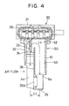
- the circuit module 20 has a circuit portion 21 protruding outside the intake pipe and a sensor unit.
- the sensor unit has a temperature sensing resistor 22 and an exothermic resistor 24. Further, as shown in FIG. 1 , the circuit module 20 has a thermistor 26 as an air temperature measuring element for measuring air temperature in the intake pipe.
- a control circuit (not shown) accommodated in the circuit portion 21 is electrically connected with the temperature sensing resistor 22, the exothermic resistor 24 and the thermistor 26 ( FIG. 1 ) through supporting members 23, 25, 27 ( FIG. 1 ).
- the control circuit controls power supply to the temperature sensing resistor 22 and the exothermic resistor 24, and outputs from a connector 28 a detection signal of air flow amount detected by the temperature sensing resistor 22 and the exothermic resistor 24 according to air flow amount in a bypass passage 40 (described later) and a detection signal of air temperature detected by the thermistor 26 ( FIG. 1 ).
- the temperature sensing resistor 22 and the exothermic resistor 24 are disposed in the vicinity of a communication portion between an upstream passage 41 and a communication passage 43 of the bypass passage 40.
- the temperature sensing resistor 22 measures temperature of air, which has contacted with the exothermic resistor 24. Therefore, preferably, the temperature sensing resistor 22 is disposed adjacent to the exothermic resistor 24 to such an extent that the temperature sensing resistor 22 is not affected by heat radiation of the exothermic resistor 24.
- the circuit portion 21 controls amount of electric current to be supplied to the exothermic resistor 24 so that difference between temperature of the exothermic resistor 24 calculated from amount of electric current to be supplied to the exothermic resistor 24, and air temperature detected by the temperature sensing resistor 22 becomes constant, and outputs the controlled amount of electric current as an air flow amount detection signal.
- the bypass member 30 has an outer tube 31, a venturi tube 35 disposed at a bottom part of the outer tube 31 to be opposite to the circuit portion 21, and a partition wall 36 extending from the venturi tube 35 toward the circuit portion 21.
- the outer tube 31, the venturi tube 35 and the partition wall 36 are integrally formed to provide the bypass member 30.
- the outer tube 31 has an upstream wall 32, a downstream wall 34 facing the upstream wall 32 with the partition wall 36 therebetween, and a pair of side walls 33 for connecting the upstream wall 32 and the downstream wall 34.
- each of the side walls 33 has a facing surface 33a.
- the facing surfaces 33a face each other in a direction perpendicular to the air flow direction in the air flow passage and to an air flow direction in the downstream passage 42.
- the venturi tube 35 has a venturi passage 35a through which part of air flowing through the air passage flows.
- the bypass passage 40 is formed by an inner wall of the outer tube 31 and the partition wall 36.
- the bypass passage 40 is partitioned by the partition wall 36 into the upstream passage 41 and the downstream passage 42.
- the bypass passage 40 is formed into U-shape including the upstream passage 41, the communication passage 43 and the downstream passage 42.
- the upstream passage 41 and the downstream passage 42 are formed parallel with each other and perpendicular to the air flow direction in the air flow passage, and are communicated with each other through the communication passage 43. A direction of air flowing from the upstream passage 41 to the downstream passage 42 changes at the communication passage 43.
- the outflow port 46 is disposed at a downstream air side of the downstream passage 42, and is communicated with the downstream passage 42.
- the outflow port 46 is surrounded at its three sides by the opposing surfaces 33a of the side walls 33 and a wall surface 36a of the partition wall 36 disposed at an upstream air side of the outflow port 46 in the air flow passage. Further, the outflow port 46 is opened in an air flow direction in the downstream passage 42 and in the air flow direction in the air flow passage. Air flowing through the bypass passage 40 is discharged through these two openings of the outflow port 46 into the air flow passage.
- a length of the downstream wall 34 is determined so that a ratio of a passage length L1 of the bypass passage 40 to a length L2 between the inlet 44 and outlet 45 of the bypass passage 40 in the air flow direction in the air flow passage is 4.0 ⁇ L1/L2 ⁇ 5.8.
- the length L1 represents a length of the bypass passage 40 from the inlet 44 to the outlet 45 at a center of the bypass passage 40. That is, the length L1 represents a length from an end of the upstream wall 32 to an end of the downstream wall 34.
- the length L2 represents a length between a center of the inlet 44 and a center of the outlet 45 in the air flow direction in the air flow passage.
- a cross-sectional area of the upstream passage 41 is smaller than that of the downstream passage 42. Therefore, air flow velocity in the upstream passage 41 is larger than that in the downstream passage 42.
- the temperature sensing resistor 22 and the exothermic resistor 24 are disposed in the vicinity of the communication portion between the upstream passage 41 and the communication passage 43, where air flow velocity is relatively large. Therefore, air flow amount can be detected by the temperature sensing resistor 22 and the exothermic resistor 24 with high accuracy, so that air flow amount is measured with high accuracy according to the detection signals.
- air flowing into the bypass passage 40 from the air flow passage 2 formed in the intake pipe separately flows into either the upstream passage 41 of the bypass passage 40 or the venturi passage 35a of the venturi pipe 35.
- Air flowing through the upstream passage 41 flows through the communication passage 43 and then through the downstream passage 42. Since air flow velocity is increased at the downstream air side of the venturi pipe 35, negative pressure is generated at the downstream air side of the venturi pipe 35. Air flowing through the bypass passage 40 is drawn by this negative pressure, so that air flow velocity in the bypass passage 40 is increased.
- a part of air flowing from the downstream passage 42 into the outflow port 46 directly joins in the main air flow discharged from the venturi passage 35a at the downstream air side of the venturi pipe 35 to be discharged from the outflow port 46 into the air flow passage 2.
- another part of air flowing from the downstream passage 42 into the outflow port 46 is discharged toward the downstream air side in the air flow passage 2 before joining in the main air flow discharged from the venturi passage 35a, because the outflow port 46 is closed by the partition wall 36 at the upstream air side in the air flow passage 2 and is opened at the downstream air side in the air flow passage 2.
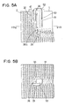
- a downstream wall 51 of an outer tube 50 extends to an upper end of the venturi tube 35. Therefore, an outlet 54 of a bypass passage 52 is opened only in an air flow direction of a downstream passage 53, and is not opened in an air flow direction of the air flow passage. That is, L1/L2 ⁇ L3/L2.
- the outflow port 46 is opened not only at the downstream air side of the downstream passage 42 but also at the downstream air side of the air flow passage 2. Therefore, air is gradually discharged into the air flow passage 2 while flowing under the downstream wall 34, before joining in main air flow from the venturi passage 35a. As a result, air flow from the bypass passage 40 smoothly joins in main air flow from the venturi passage 35a in the air flow passage.
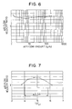
- air flow velocity in the bypass passage 52 in the first embodiment is larger than that in the comparative example regardless of air flow amount in the air flow passage.
- the air flow velocity ratio represents a ratio of the air flow velocity in the bypass passage 40 in the first embodiment to the air flow velocity in the bypass passage 52 in the comparative example.
- pulsation generated in the bypass passage 40 can be decreased by adjusting L1 and L2 so that L1/L2 is defined as 4.0 ⁇ L2/L1 ⁇ 5.8.
- a passage length of the downstream passage 42 is held under a predetermined value. Therefore, air flowing from the upstream passage 41 to the downstream passage 42 while changing its air flow direction includes air flowing in the air flow direction in the venturi tube 35, when joining in air flow from the venturi tube 35. As a result, air flow from the bypass passage 40 and air flow from the venturi passage 35a join together smoothly. Further, air flow in the bypass passage 40 is drawn by negative pressure generated at the downstream air side of the venturi pipe 35. Therefore, as shown in FIG. 7 , air flow velocity in the bypass passage in the first embodiment is increased in comparison with that in the comparative example, provided that air flow amount in the air flow passage in the first embodiment is the same as that in the comparative example.
- FIGS. 8, 9 A second embodiment of the present invention will be described with reference to FIGS. 8, 9 .
- component parts which are substantially the same as those in the first embodiment are indicated with the same reference numerals.
- An air flow meter 11 has a bypass member 60 having an outer tube 61 and a partition wall 65.
- the outer tube 61 has an upstream wall 62, a downstream wall 64 facing the upstream wall 62 with the partition wall 65 therebetween, and side walls 62 for connecting the upstream wall 62 and the downstream wall 64.
- the partition wall 65 partitions the bypass passage 70 into an upstream passage 71 and a downstream passage 72.
- An outflow port 73 is communicated with the downstream passage 72 and is disposed at a downstream air side of the downstream passage 72. Further, the outflow port 73 is surrounded at its three sides by opposing surfaces 63a of the side walls 63 and an inner wall surface 65a of the partition wall 65. The inner wall surface 65a is disposed at an upstream air side of the outflow port 73.
- the outflow port 73 is opened in an air flow direction in the downstream passage 76 and in an air flow direction in the air flow passage 2, so that air flowing through the bypass passage 70 is discharged through these two openings.
- the bypass member 60 does not have a venturi tube. Therefore, air flow velocity in the bypass passage 70 is smaller than in the first embodiment. However, air is gradually discharged from the outflow port 73 into the air flow passage 2, thereby restricting air flow velocity in the bypass passage from decreasing and decreasing turbulence in the bypass passage.
- the outflow port of the bypass passage is closed at the upstream air side by the partition wall, and is opened in the air flow direction of the downstream passage and in the air flow direction of the air flow passage. Therefore, air flowing through the bypass passage is gradually discharged through the outflow port into the air flow passage before joining in the main air flow in the air flow passage. As a result, air flow in the bypass passage smoothly joins in the main air flow in the air flow passage, thereby restricting air flow velocity in the bypass passage from decreasing and decreasing turbulence in the bypass passage. Therefore, the sensor unit detects air flow amount in the bypass passage with high accuracy.
- the bypass passage has a substantially square-shaped cross-section.
- the bypass passage may have a cross-section of any other shapes, such as a circle.
- the present invention is not limited to a device for measuring air flow amount for an internal combustion engine, but may be applied to a device for measuring air flow amount in various air flow passages.
Landscapes
- Physics & Mathematics (AREA)
- Fluid Mechanics (AREA)
- General Physics & Mathematics (AREA)
- Measuring Volume Flow (AREA)
Claims (5)
- Luftstrommesser zum Messen einer Luftstrommenge in einem Luftstromdurchgang (2), wobei der Luftstrommesser Folgendes aufweist:ein Umgehungsbauteil (30), das in dem Luftstromdurchgang (2) angeordnet ist, das ein Außenrohr (31) hat und einen Umgehungsdurchgang (40) ausbildet, in welchen Luft, die durch den Luftstromdurchgang hindurch strömt, teilweise hinein strömt, wobei das Außenrohr (31) eine stromaufwärtige Wand (32), eine stromabwärtige Wand (34), die der stromaufwärtigen Wand (32) mit einer Trennwand (36) dazwischen gegenüberliegt, und ein paar Seitenwände (33) hat, um die stromaufwärtige Wand (32) und die stromabwärtige Wand (34) zu verbinden, sodass der Umgehungsdurchgang einen stromaufwärtigen Durchgang (41) und einen stromabwärtigen Durchgang (42) aufweist, die durch einen Verbindungsdurchgang (43) verbunden sind, wobei der stromabwärtige Durchgang (42) den Luftstromdurchgang so kreuzt, dass Luft, die durch den Umgehungsdurchgang (40) hindurch strömt, von diesem abgegeben wird; undeine Sensoreinheit, die in dem Umgehungsdurchgang (40) angeordnet ist,wobei der Umgehungsdurchgang (40) Folgendes hat:einen Ausströmanschluss (46, 73), der an einer Stromabwärtsluftseite des stromabwärtigen Durchgangs (42) stromabwärts der Trennwand (36), die mit dem stromabwärtigen Durchgang (42) verbunden ist, angeordnet ist, wobei der Ausströmanschluss (46, 73) an drei Seiten von einer Fläche, die an einer Stromaufwärtsluftseite des Luftstromdurchgangs angeordnet ist, und gegenüberliegenden Flächen umgeben ist, die in einer Richtung senkrecht zu einer Luftstromrichtung in dem Luftstromdurchgang und zu einer Luftstromrichtung in dem stromabwärtigen Durchgang (42) einander zugewandt sind, und wobei der Ausströmanschluss (46, 73) in der Luftstromrichtung in dem Luftstromdurchgang und in der Luftstromrichtung in dem stromabwärtigen Durchgang (42) geöffnet ist, wobeider Ausströmanschluss (46, 73) auch an der Stromabwärtsluftseite des stromabwärtigen Durchgangs (42) und an der Stromabwärtsluftseite des Luftstromdurchgangs (2) geöffnet ist, wobei der Ausströmanschluss (46, 73) durch die Trennwand (36) an der Stromaufwärtsluftseite in dem Luftstromdurchgang (2) geschlossen ist und an der Stromabwärtsluftseite in dem Luftstromdurchgang (2) geöffnet ist, wodurch bewirkt wird, dass ein Teil der Luft von dem stromabwärtigen Durchgang (42) in den Ausströmanschluss (46, 73) strömt, um sich direkt mit dem Hauptluftstrom zu vereinigen, der von dem Ausströmanschluss (46, 73) in den Luftstromdurchgang (2) abgegeben wird, wobei ein weiterer Teil der Luft, die von dem stromabwärtigen Durchgang (42) in den Ausströmanschluss (46, 73) strömt, in Richtung der Stromabwärtsluftseite in den Luftstromdurchgang (2) abgegeben wird, bevor sich dieser mit dem Hauptluftstrom vereinigt, der von dem Ausströmanschluss (46, 73) abgegeben wird.
- Luftstrommesser nach Anspruch 1, wobei
der Umgehungsdurchgang (40), der den stromabwärtigen Durchgang (42) hat, in U-Form ausgebildet ist. - Luftstrommesser nach Anspruch 2, wobei
ein Verhältnis von einer ersten Länge L1 des Umgehungsdurchgangs (40) zu einer zweiten Länge L2 zwischen der Mitte des Einlassbereiches (44) und einer Mitte des Auslassbereiches (45) des Luftstromdurchgangs in Ebenen parallel zu dem Luftstrom in der Luftstromrichtung definiert ist als 4,0 ≤ L1/L2 ≤ 5,8, wobei die erste Länge L1 eine Länge von einem Ende der stromaufwärtigen Wand (32) zu einem Ende der stromabwärtigen Wand (34) darstellt, und die zweite Länge L2 eine Länge zwischen einer Mitte des Einlassbereiches (44) und einer Mitte des Auslassbereiches (45) in der Luftstromrichtung in dem Luftstromdurchgang darstellt. - Luftstrommesser nach Anspruch 2, wobei
das Umgehungsbauteil (30) einen Venturi-Durchgang (35a) hat, welcher Luft von dem Umgehungsdurchgang (40) ansaugt. - Luftstrommesser nach Anspruch 1, wobei ein Venturi-Rohr (35) an einem Unterseitenteil des Außenrohres (31) angeordnet ist, um entgegengesetzt zu einem Schaltkreisabschnitt (21) zu sein, der außerhalb von einem Einlassrohr und der Sensoreinheit vorsteht, und die Trennwand (36) sich von dem Venturi-Rohr (35) in Richtung des Schaltkreisabschnitts (21) erstreckt.
Applications Claiming Priority (2)
| Application Number | Priority Date | Filing Date | Title |
|---|---|---|---|
| JP5464098 | 1998-03-06 | ||
| JP05464098A JP3758111B2 (ja) | 1998-03-06 | 1998-03-06 | 空気流量測定装置 |
Publications (3)
| Publication Number | Publication Date |
|---|---|
| EP0940657A2 EP0940657A2 (de) | 1999-09-08 |
| EP0940657A3 EP0940657A3 (de) | 2000-08-16 |
| EP0940657B1 true EP0940657B1 (de) | 2015-07-29 |
Family
ID=12976384
Family Applications (1)
| Application Number | Title | Priority Date | Filing Date |
|---|---|---|---|
| EP99104503.0A Expired - Lifetime EP0940657B1 (de) | 1998-03-06 | 1999-03-05 | Luftdurchflussmesser |
Country Status (3)
| Country | Link |
|---|---|
| US (1) | US6220090B1 (de) |
| EP (1) | EP0940657B1 (de) |
| JP (1) | JP3758111B2 (de) |
Families Citing this family (22)
| Publication number | Priority date | Publication date | Assignee | Title |
|---|---|---|---|---|
| KR20010039993A (ko) * | 1999-10-06 | 2001-05-15 | 오카무라 가네오 | 유량 및 유속 측정장치 |
| JP2002005713A (ja) * | 2000-04-17 | 2002-01-09 | Denso Corp | 空気流量測定装置 |
| DE10046943A1 (de) * | 2000-09-21 | 2002-04-18 | Siemens Ag | Massenstrommesser |
| WO2003008913A1 (fr) * | 2001-07-18 | 2003-01-30 | Hitachi, Ltd. | Equipement de mesure du debit d'un gaz |
| US7467546B2 (en) * | 2001-07-18 | 2008-12-23 | Hitachi, Ltd. | Equipment for measuring gas flow rate |
| JP3785338B2 (ja) * | 2001-07-25 | 2006-06-14 | 株式会社日立製作所 | 熱式流量計測装置 |
| DE10141909B4 (de) * | 2001-08-28 | 2005-11-17 | Siemens Ag | Luftmassendurchflussmesser |
| US6622555B2 (en) | 2001-10-11 | 2003-09-23 | Visteon Global Technologies, Inc. | Fluid flow meter |
| US6938473B2 (en) * | 2001-11-19 | 2005-09-06 | Denso Corporation | Apparatus for measuring flow amount |
| US6708561B2 (en) | 2002-04-19 | 2004-03-23 | Visteon Global Technologies, Inc. | Fluid flow meter having an improved sampling channel |
| US6826955B2 (en) * | 2002-09-20 | 2004-12-07 | Visteon Global Technologies, Inc. | Mass fluid flow sensor having an improved housing design |
| US6973825B2 (en) * | 2003-02-24 | 2005-12-13 | Visteon Global Technologies, Inc. | Hot-wire mass flow sensor with low-loss bypass passage |
| DE10316450B4 (de) * | 2003-04-10 | 2019-08-08 | Robert Bosch Gmbh | Vorrichtung zur Bestimmung wenigstens eines Parameters eines in einer Leitung strömenden Mediums |
| JP3848934B2 (ja) * | 2003-05-16 | 2006-11-22 | 三菱電機株式会社 | 空気流量測定装置 |
| JP4072860B2 (ja) * | 2004-06-15 | 2008-04-09 | 株式会社デンソー | 内燃機関の吸入空気量検出装置 |
| DE102006024745A1 (de) * | 2006-05-26 | 2007-12-06 | Siemens Ag | Massenstromsensorvorrichtung |
| DE102006045657A1 (de) | 2006-09-27 | 2008-04-03 | Robert Bosch Gmbh | Steckfühler mit optimiertem Strömungsauslass |
| JP5195819B2 (ja) * | 2010-06-02 | 2013-05-15 | 株式会社デンソー | 空気流量測定装置 |
| JP5201187B2 (ja) * | 2010-09-30 | 2013-06-05 | 株式会社デンソー | 空気流量計測装置 |
| JP5263324B2 (ja) | 2011-03-24 | 2013-08-14 | 株式会社デンソー | 空気流量測定装置 |
| DE102011080894A1 (de) * | 2011-08-12 | 2013-02-14 | Endress + Hauser Flowtec Ag | Sensor-Modul zum Messen und/oder Überwachen von Parametern von in Rohrleitungen strömenden Medien sowie damit gebildetes Meßsystem |
| EP3546955B1 (de) * | 2019-05-24 | 2021-12-08 | Sensirion AG | Leitungssensor mit leitungssonde zur entnahme einer flüssigkeit aus einer leitung und verfahren zum betrieb |
Family Cites Families (9)
| Publication number | Priority date | Publication date | Assignee | Title |
|---|---|---|---|---|
| US3559482A (en) * | 1968-11-27 | 1971-02-02 | Teledyne Inc | Fluid flow measuring apparatus |
| JPS56108908A (en) * | 1980-01-31 | 1981-08-28 | Hitachi Ltd | Detector for sucked air flow rate of internal combustion engine |
| JPH0617810B2 (ja) | 1988-02-12 | 1994-03-09 | 株式会社日立製作所 | 熱式空気流量計 |
| JP3235872B2 (ja) | 1992-07-03 | 2001-12-04 | 株式会社タカショー | パイプ状物の接続部材 |
| JP2846207B2 (ja) * | 1992-09-17 | 1999-01-13 | 株式会社日立製作所 | 空気流量測定装置 |
| US5537870A (en) | 1994-10-03 | 1996-07-23 | Ford Motor Company | Contaminant free backflow reducing insert for mass air flow sensors |
| US5595163A (en) * | 1995-06-06 | 1997-01-21 | Hitachi America, Ltd. | Apparatus and method for controlling the fuel supply of a gas-fueled engine |
| JP3189636B2 (ja) | 1995-08-03 | 2001-07-16 | 株式会社日立製作所 | 発熱抵抗式流量測定装置 |
| US5804718A (en) | 1996-04-24 | 1998-09-08 | Denso Corporation | Airflow meter having an inverted u-shape bypass passage |
-
1998
- 1998-03-06 JP JP05464098A patent/JP3758111B2/ja not_active Expired - Lifetime
-
1999
- 1999-02-22 US US09/253,539 patent/US6220090B1/en not_active Expired - Lifetime
- 1999-03-05 EP EP99104503.0A patent/EP0940657B1/de not_active Expired - Lifetime
Also Published As
| Publication number | Publication date |
|---|---|
| JPH11248504A (ja) | 1999-09-17 |
| EP0940657A2 (de) | 1999-09-08 |
| JP3758111B2 (ja) | 2006-03-22 |
| US6220090B1 (en) | 2001-04-24 |
| EP0940657A3 (de) | 2000-08-16 |
Similar Documents
| Publication | Publication Date | Title |
|---|---|---|
| EP0940657B1 (de) | Luftdurchflussmesser | |
| EP0708315B1 (de) | Thermische Vorrichtung zum Messen der Luftströmung | |
| US6223594B1 (en) | Thermal type air flow amount measuring apparatus having flow rectifier | |
| US20010049970A1 (en) | Fluid flow meter having thermal flow sensor | |
| CN1194690A (zh) | 测量流动介质的量的装置 | |
| EP0295845B1 (de) | Durchflussoszillator | |
| US7258002B2 (en) | Fluid flow detecting apparatus | |
| KR20170056552A (ko) | 채널 구조를 관류하는 유체 매체의 적어도 하나의 매개변수를 측정하기 위한 센서 장치 | |
| US20010037678A1 (en) | Air flow meter having turbulence reduction member | |
| JPH04157325A (ja) | 熱式空気流量計 | |
| WO2002103301A1 (fr) | Instrument de mesure de debit d'une resistance thermique | |
| JP2000310552A (ja) | 空気流量計 | |
| JP3561219B2 (ja) | 発熱抵抗式流量測定装置 | |
| EP1363109B1 (de) | Strömungsmesser mit widerstandsheizelement | |
| JPH07190821A (ja) | 流量計 | |
| JPH09236460A (ja) | カルマン渦式流量計 | |
| JP3593011B2 (ja) | 発熱抵抗式流量測定装置 | |
| JPH08159833A (ja) | 流量測定装置 | |
| JPH0320619A (ja) | 熱線式空気流量計 | |
| JP4132169B2 (ja) | 吸気装置 | |
| JP3593042B2 (ja) | 発熱抵抗式流量測定装置 | |
| JPH06288805A (ja) | 空気流量計 | |
| JPH0943020A (ja) | 発熱抵抗式流量測定装置 | |
| JP3014888B2 (ja) | 流量計 | |
| JPS61134622A (ja) | 質量空気流量測定装置 |
Legal Events
| Date | Code | Title | Description |
|---|---|---|---|
| PUAI | Public reference made under article 153(3) epc to a published international application that has entered the european phase |
Free format text: ORIGINAL CODE: 0009012 |
|
| AK | Designated contracting states |
Kind code of ref document: A2 Designated state(s): DE FR GB |
|
| AX | Request for extension of the european patent |
Free format text: AL;LT;LV;MK;RO;SI |
|
| PUAL | Search report despatched |
Free format text: ORIGINAL CODE: 0009013 |
|
| AK | Designated contracting states |
Kind code of ref document: A3 Designated state(s): AT BE CH CY DE DK ES FI FR GB GR IE IT LI LU MC NL PT SE |
|
| AX | Request for extension of the european patent |
Free format text: AL;LT;LV;MK;RO;SI |
|
| RIC1 | Information provided on ipc code assigned before grant |
Free format text: 7G 01F 5/00 A, 7G 01F 1/684 B |
|
| 17P | Request for examination filed |
Effective date: 20000913 |
|
| AKX | Designation fees paid |
Free format text: DE FR GB |
|
| 17Q | First examination report despatched |
Effective date: 20080415 |
|
| APBK | Appeal reference recorded |
Free format text: ORIGINAL CODE: EPIDOSNREFNE |
|
| APBN | Date of receipt of notice of appeal recorded |
Free format text: ORIGINAL CODE: EPIDOSNNOA2E |
|
| APBR | Date of receipt of statement of grounds of appeal recorded |
Free format text: ORIGINAL CODE: EPIDOSNNOA3E |
|
| APAF | Appeal reference modified |
Free format text: ORIGINAL CODE: EPIDOSCREFNE |
|
| APBT | Appeal procedure closed |
Free format text: ORIGINAL CODE: EPIDOSNNOA9E |
|
| GRAP | Despatch of communication of intention to grant a patent |
Free format text: ORIGINAL CODE: EPIDOSNIGR1 |
|
| INTG | Intention to grant announced |
Effective date: 20150424 |
|
| GRAS | Grant fee paid |
Free format text: ORIGINAL CODE: EPIDOSNIGR3 |
|
| GRAA | (expected) grant |
Free format text: ORIGINAL CODE: 0009210 |
|
| AK | Designated contracting states |
Kind code of ref document: B1 Designated state(s): DE FR GB |
|
| REG | Reference to a national code |
Ref country code: GB Ref legal event code: FG4D |
|
| REG | Reference to a national code |
Ref country code: DE Ref legal event code: R096 Ref document number: 69945373 Country of ref document: DE |
|
| REG | Reference to a national code |
Ref country code: DE Ref legal event code: R084 Ref document number: 69945373 Country of ref document: DE |
|
| REG | Reference to a national code |
Ref country code: GB Ref legal event code: 746 Effective date: 20160222 |
|
| REG | Reference to a national code |
Ref country code: FR Ref legal event code: PLFP Year of fee payment: 18 |
|
| REG | Reference to a national code |
Ref country code: DE Ref legal event code: R097 Ref document number: 69945373 Country of ref document: DE |
|
| PLBE | No opposition filed within time limit |
Free format text: ORIGINAL CODE: 0009261 |
|
| STAA | Information on the status of an ep patent application or granted ep patent |
Free format text: STATUS: NO OPPOSITION FILED WITHIN TIME LIMIT |
|
| 26N | No opposition filed |
Effective date: 20160502 |
|
| REG | Reference to a national code |
Ref country code: FR Ref legal event code: PLFP Year of fee payment: 19 |
|
| REG | Reference to a national code |
Ref country code: FR Ref legal event code: PLFP Year of fee payment: 20 |
|
| PGFP | Annual fee paid to national office [announced via postgrant information from national office to epo] |
Ref country code: DE Payment date: 20180322 Year of fee payment: 20 Ref country code: GB Payment date: 20180321 Year of fee payment: 20 |
|
| PGFP | Annual fee paid to national office [announced via postgrant information from national office to epo] |
Ref country code: FR Payment date: 20180323 Year of fee payment: 20 |
|
| REG | Reference to a national code |
Ref country code: DE Ref legal event code: R071 Ref document number: 69945373 Country of ref document: DE |
|
| REG | Reference to a national code |
Ref country code: GB Ref legal event code: PE20 Expiry date: 20190304 |
|
| PG25 | Lapsed in a contracting state [announced via postgrant information from national office to epo] |
Ref country code: GB Free format text: LAPSE BECAUSE OF EXPIRATION OF PROTECTION Effective date: 20190304 |