EP0940291A2 - Strassenfahrzeug zum Transport und Magazinieren von Verkehrsschildern - Google Patents
Strassenfahrzeug zum Transport und Magazinieren von Verkehrsschildern Download PDFInfo
- Publication number
- EP0940291A2 EP0940291A2 EP99250054A EP99250054A EP0940291A2 EP 0940291 A2 EP0940291 A2 EP 0940291A2 EP 99250054 A EP99250054 A EP 99250054A EP 99250054 A EP99250054 A EP 99250054A EP 0940291 A2 EP0940291 A2 EP 0940291A2
- Authority
- EP
- European Patent Office
- Prior art keywords
- road vehicle
- trailer
- footplate
- traffic signs
- vehicle according
- Prior art date
- Legal status (The legal status is an assumption and is not a legal conclusion. Google has not performed a legal analysis and makes no representation as to the accuracy of the status listed.)
- Granted
Links
- 230000008878 coupling Effects 0.000 description 2
- 238000010168 coupling process Methods 0.000 description 2
- 238000005859 coupling reaction Methods 0.000 description 2
- 230000002349 favourable effect Effects 0.000 description 2
- 238000009434 installation Methods 0.000 description 2
- 230000001960 triggered effect Effects 0.000 description 2
Images


Classifications
-
- B—PERFORMING OPERATIONS; TRANSPORTING
- B60—VEHICLES IN GENERAL
- B60P—VEHICLES ADAPTED FOR LOAD TRANSPORTATION OR TO TRANSPORT, TO CARRY, OR TO COMPRISE SPECIAL LOADS OR OBJECTS
- B60P3/00—Vehicles adapted to transport, to carry or to comprise special loads or objects
-
- E—FIXED CONSTRUCTIONS
- E01—CONSTRUCTION OF ROADS, RAILWAYS, OR BRIDGES
- E01F—ADDITIONAL WORK, SUCH AS EQUIPPING ROADS OR THE CONSTRUCTION OF PLATFORMS, HELICOPTER LANDING STAGES, SIGNS, SNOW FENCES, OR THE LIKE
- E01F9/00—Arrangement of road signs or traffic signals; Arrangements for enforcing caution
- E01F9/60—Upright bodies, e.g. marker posts or bollards; Supports for road signs
- E01F9/70—Storing, transporting, placing or retrieving portable devices
Definitions
- the invention relates to a road vehicle for transporting and magazining traffic signs, that is used when moving signs for road signs becomes.
- the installation or clearing of a large number of portable traffic signs along a larger route requires the use of a road vehicle.
- a built-in, hydraulically operated tail lift is used as a loading aid in order to facilitate the frequent lifting of the heavy footplate stands.
- the loading platform of the truck is longitudinally separated by a wooden wall.
- the two rooms created in this way serve to accommodate the traffic signs, including the shaft tubes, which are attached to hook strips.
- the footplate stands are arranged in a stack in the rear area of the loading platform.
- the disadvantage here is that the traffic signs and the footplate stand must first be carried to the loading platform and brought to the installation site after the loading tailgate has been shut down.
- a road vehicle is also known which has a box body with compartments and a separate base frame which is pivotally equipped by means of a jack. This provides flexibility, but loading and unloading is done manually.
- the object of the invention is a road vehicle for transport and storage of traffic signs to create unloading at a desired location or collecting the heavy footplate stands holding the traffic signs facilitated, while ensuring the safety of people and road traffic remains.
- the road vehicle for transporting and storing portable traffic signs is known to consist of a tractor to which a semi-trailer is coupled by means of a fifth wheel coupling.
- the trailer is cranked and consists of a front part and a low-lying rear part with a tandem or triple axis.
- a magazine device for the footplate stands and traffic signs with shaft tubes is arranged in this rear part.
- the rear part is provided with a downward sloping end.
- the magazine device consists of an endless pull chain on which rollers with devices for receiving the footplate stand, for example hooks, are arranged at certain intervals.
- the front cranked part of the trailer is boxed and has compartments with flaps that can be opened to the side to accommodate the accessories.
- the rear part of the semi-trailer is provided with a box body, the rear surface of which is designed as a flap that can be opened by means of hydraulics, pneumatics or spring relief.
- a truck 1 with a fifth wheel coupling is used as the tractor because of its maneuverability with a short wheelbase.
- the trailer 2 is cranked and provided with a tandem or triple axle 3 with the smallest possible wheels, but according to the required payload, to keep the height of the loading area as low as possible.
- the rear overhanging part of this loading area 4 is additionally inclined downward, so that the rear loading edge is as low as possible while maintaining a practicable ground clearance.
- the trailer is provided with a box body 5, the rear surface of which is designed as a flap 6 and can be opened by means of hydraulics, pneumatics or spring relief.
- the front, cranked part 7 of the trailer has a case, has compartments and flaps that can be opened from the side, and also accommodates accessories.
- hydraulically, pneumatically or electromechanically driven rollers, rollers, cable or chain hoists are arranged, which reposition the heavy footplate stand 9 from or into the storage position to or from the unloading or loading point enable.
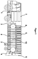
- the transport magazine 10 is shown in FIG. 2.
- a footplate stand 9 is brought into the loading station 11 and tilted there by hand and / or with a suitable device, which is hydraulically, electrically or mechanically supported, until it reaches a hook-shaped holder provided thereon or a suitable engagement point provided on it Bracket 12 tilts.
- This hook 12 is pivotally attached to rollers 13 which are guided on or in rails 14. These rollers 13 are transported in the marked direction together with the hook 12 and the footplate stand 9 hanging thereon by means of a pull chain 15 attached to its axis. The transport movement is triggered by the operating personnel and takes place step by step with the path of the division (a).
- a plurality of the hooks 12 described are located on the pull chain 15.
- the base plate stands 9 are pivoted in their position by the rails 14 and also form a tight, space-saving package above the device.
- the footplate stand 9 slips out of the hook 12 due to its own weight and then tilts into the unloading station 16. From there, the footplate stand 9 is moved into an ergonomically favorable removal position by means of a suitable device that is hydraulically, electrically or mechanically supported brought.
- FIG. 3 Another transport magazine 10 is described in FIG. 3.
- the footplate stand 9, according to FIG. 2, is brought into the loading station 11 and tilted there by hand and / or with a suitable device which is hydraulically, electrically or mechanically supported, until it is provided with a holder provided thereon or a tilts a suitable engagement point in a hook-shaped holder 12.
- This hook 12 is pivotally attached to rollers 13 which are guided on or in rails 14. These rollers 13 are transported in the marked direction together with the hook 12 and the footplate stand 9 hanging thereon by means of a pull chain 15 attached to its axis.
- the transport movement is triggered by the operating personnel and takes place step by step with the path of the division (a).
- a plurality of the hooks 12 described are located on the pull chain 15.
- the unloading station 16 is identical to the loading station 11. Because of its own weight, the footplate stand 9 slips out of the hook 12 and then tilts into the unloading station 16. From there, the footplate stand 9 is moved in by means of a suitable device which is hydraulically, electrically or mechanically supported brought an ergonomically favorable removal position.
Landscapes
- Engineering & Computer Science (AREA)
- Health & Medical Sciences (AREA)
- Public Health (AREA)
- Transportation (AREA)
- Mechanical Engineering (AREA)
- Architecture (AREA)
- Civil Engineering (AREA)
- Structural Engineering (AREA)
- Loading Or Unloading Of Vehicles (AREA)
- Handcart (AREA)
- Jib Cranes (AREA)
Abstract
Description
Zur Bewältigung des Höhenunterschiedes zwischen Ladefläche und Fahrbahn oder Gehweg wird als Ladehilfe eine eingebaute hydraulisch betriebene Ladebordwand verwendet, um das oftmalige Heben der schweren Fußplattenständer zu erleichtern. Die Ladeplattform des Lastkraftwagens ist in Längsrichtung mittig durch eine Holzwand getrennt. Die so entstandenen zwei Räume dienen zur Aufnahme der Verkehrsschilder einschließlich der Schaftrohre, die an Hakenleisten befestigt sind. Im hinteren Bereich der Ladeplattform sind die Fußplattenständer stapelförmig angeordnet. Nachteilig hierbei ist, daß die Verkehrsschilder und die Fußplattenständer erst zur Ladeplattform getragen und nach dem Herunterfahren der Ladebordwand zum Aufstellort gebracht werden müssen.
Aus der DE-OS 25 05 860 ist ebenfalls ein Straßenfahrzeug bekannt, das einen Kofferaufbau mit Fächern und einen separaten Grundrahmen, der schwenkbeweglich mittels Hubstempel ausgestattet ist, aufweist. Damit ist die Beweglichkeit gegeben, jedoch das Be- und Entladen erfolgt manuell.
Der Aufliegeranhänger ist gekröpft ausgebildet und besteht aus einem vorderen Teil und einem tiefliegenden, mit einer Tandem- oder Dreifachachse versehenen hinteren Teil. In diesem hinteren Teil ist eine Magaziniereinrichtung für die Fußplattenständer und Verkehrsschilder mit Schaftrohren angeordnet. Der hintere Teil ist am Ende mit einer nach unten geneigten Schräge versehen.
Die Magaziniereinrichtung besteht aus einer Endloszugkette, auf der in bestimmten Abständen Rollen mit Einrichtungen zur Aufnahme der Fußplattenständer, beispielsweise Haken, angeordnet sind.
Der vordere gekröpfte Teil des Aufliegeranhängers ist überkoffert und weist Fächer mit seitlich zu öffnenden Klappen zur Unterbringung des mitruführenden Zubehörs auf. Desweiteren ist der hintere Teil des Aufliegeranhängers mit einem Kofferaufbau versehen, dessen Heckfläche als mittels Hydraulik, Pneumatik oder Federentlastung zu öffnende Klappe ausgebildet ist.
Mit diesem Straßenfahrzeug ist der Transport und das Magazinieren einschließlich das Be- und Entladen von ortsveränderlichen Verkehrsschildern gesichert.
Der Aufliegeranhänger 2 ist gekröpft und mit einer Tandem- oder Dreifach-Achse 3 mit möglichst kleinen Rädern, aber entsprechend der erforderlichen Nutzlast, versehen, um die Höhe der Ladefläche so niedrig wie möglich zu halten.
Der hintere überhängende Teil dieser Ladefläche 4 ist zusätzlich nach unten geneigt, so daß die hintere Ladekante unter Einhaltung einer praktikablen Bodenfreiheit so niedrig wie möglich ist.
Der Auflieger ist mit einem Kofferaufbau 5 versehen, dessen Heckfläche als Klappe 6 ausgebildet ist und mittels Hydraulik, Pneumatik oder Federentlastung zu öffnen ist. Der vordere, gekröpfte Teil 7 des Aufliegers ist überkoffert, hat Fächer und seitlich zu öffnende Klappen und nimmt zusätzlich mitführendes Zubehör auf.
Die von den Fußplattenständern üblicherweise getrennt mitgeführten Verkehrsschilder 8, beispielsweise fest an die Schaftrohre montiert, werden mit einer entsprechenden Halterung versehen, an der Decke des Kofferaufbaus ebenfalls in einer hydraulisch, pneumatisch oder elektromechanisch angetriebenen Fördereinrichtung gehaltert, und können nach Bedarf aus der oder in die Lagerposition zu oder von der Ent- oder Beladestelle bewegt werden.
Entweder in den Boden des tiefliegenden Kofferaufpaus intergriert oder auf diesen aufgebaut sind hydraulisch, pneumatisch oder elektromechanisch angetriebene Rollen, Walzen, Seil- oder Kettenzüge angeordnet, die das Umpositionieren der schweren Fußplattenständer 9 aus der oder in die Lagerposition zu oder von der Ent- oder Beladestelle ermöglichen.
Ein Fußplattenständer 9 wird in die Beladestation 11 gebracht und dort von Hand und/oder mit einer geeigneten Einrichtung, die hydraulisch, elektrisch oder mechanisch unterstützt ist, angekippt, bis dieser einer an ihm dafür vorgesehenen Halterung oder einem an ihm vorhandenen geeigneten Angriffspunkt in eine hakenförmige Halterung 12 kippt.
Diese Rollen 13 werden zusammen mit dem Haken 12 und dem daran hängenden Fußplattenständer 9 mittels einer an ihrer Achse befestigten Zugkette 15 in die markierte Richtung transportiert.
Die Transportbewegung wird von dem Bedienungspersonal ausgelöst und erfolgt schrittweise mit dem Weg der Teilung (a).
Entsprechend der Teilung (a) befindet sich eine Vielzahl der beschriebenen Haken 12 an der Zugkette 15.
Am Umkehrpunkt des Kettentriebes werden die Fußplattenständer 9 durch die Schienen 14 in ihrer Lage verschwenkt und bilden auch oberhalb der Einrichtung ein dichtes platzsparendes Paket.
Der Entladestation 16 sich nähernd, rutscht der Fußplattenständer 9 durch sein Eigengewicht aus dem Haken 12 und kippt anschließend in die Entladestation 16. Von dort wird der Fußplattenständer 9 mittels einer geeigneten Einrichtung, die hydraulisch, elektrisch oder mechanisch unterstützt ist, in eine ergonomisch günstige Entnahmeposition gebracht.
Der Fußplattenständer 9 wird, entsprechend der Fig. 2, in die Beladestation 11 gebracht und dort von Hand und/oder mit einer geeigneten Einrichtung, die hydraulisch, elektrisch oder mechanisch unterstützt ist, angekippt, bis dieser mit einer an ihm dafür vorgesehenen Halterung oder einem an ihm vorhandenen geeigneten Angriffspunkt in eine hakenförmige Halterung 12 kippt.
Dieser Haken 12 ist an Rollen 13 schwenkbar befestigt, die auf oder in Schienen 14 geführt werden.
Diese Rollen 13 werden zusammen mit dem Haken 12 und dem daran hängenden Fußplattenständer 9 mittels einer an ihrer Achse befestigten Zugkette 15 in die markierte Richtung transportiert.
Entsprechend der Teilung (a) befindet sich eine Vielzahl der beschriebenen Haken 12 an der Zugkette 15.
Am Umkehrpunkt des Kettentriebes bleiben die Fußplattenständen 9 aufgrund des Eigengewichtes in ihrer Lage und bilden innerhalb der Einrichtung, am rückläufigen Teil der Zugkette hängend, ebenfalls ein dichtes platzsparendes Paket.
Die Entladestation 16 ist identisch mit der Beladestation 11. Der Fußplattenständer 9 rutscht durch sein Eigengewicht aus dem Haken 12 und kippt anschließend in die Entladestation 16. Von dort wird der Fußplattenständer 9 mittels einer geeigneten Einrichtung, die hydraulisch, elektrisch oder mechanisch unterstützt ist, in eine ergonomisch günstige Entnahmeposition gebracht.
Claims (5)
- Straßenfahrzeug zum Transportieren und Magazinieren von ortsveränderlichen Verkehrsschildern, bestehend aus einer Zugmaschine, an die mittels Sattelkupplung ein Aufliegeranhänger angekuppelt ist,
dadurch gekennzeichnet, daß
der Aufliegeranhänger gekröpft ausgebildet ist und aus einem vorderen Teil (7) und einem tieferliegenden, mit einer Tandem- oder Dreifachachse (3) versehenen hinteren Teil (2) besteht, wobei eine Magazineinrichtung (10) für die Fußplattenständer (9) und Verkehrsschilder (8) mit Schaftrohren in diesem hinteren Teil (2) angeordnet ist. - Straßenfahrzeug nach Anspruch 1,
dadurch gekennzeichnet, daß
der hintere Teil (2) des Aufliegeranhängers am Ende mit einer nach unten geneigten Schräge (4) versehen ist. - Straßenfahrzeug nach den Ansprüchen 1 bis 2,
dadurch gekennzeichnet, daß
die Magaziniereinrichtung (10) aus einer Endloszugkette (15) besteht, auf der in bestimmten Abständen Rollen (13) mit Einrichtungen zur Aufnahme der Fußplattenständer (9), beispielsweise Haken (12), angeordnet sind. - Straßenfahrzeug nach den Ansprüchen 1 bis 4,
dadurch gekennzeichnet, daß
der vordere gekröpfte Teil (7) des Aufliegeranhängers überkoffert ist und Fächer mit seitlich zu öffnenden Klappen aufweist. - Straßenfahrzeug nach den Ansprüchen 1 bis 3,
dadurch gekennzeichnet, daß
der hintere Teil (2) des Aufliegeranhängers mit einem Kofferaufbau (5) versehen ist, dessen Heckfläche als mittels Hydraulik, Pneumatik oder Federentlastung zu öffnende Klappe (6) ausgebildet ist.
Applications Claiming Priority (2)
| Application Number | Priority Date | Filing Date | Title |
|---|---|---|---|
| DE19810769A DE19810769C2 (de) | 1998-03-06 | 1998-03-06 | Straßenfahrzeug zum Transport und Magazinieren von Verkehrsschildern |
| DE19810769 | 1998-03-06 |
Publications (3)
| Publication Number | Publication Date |
|---|---|
| EP0940291A2 true EP0940291A2 (de) | 1999-09-08 |
| EP0940291A3 EP0940291A3 (de) | 2001-12-19 |
| EP0940291B1 EP0940291B1 (de) | 2003-01-02 |
Family
ID=7860663
Family Applications (1)
| Application Number | Title | Priority Date | Filing Date |
|---|---|---|---|
| EP99250054A Expired - Lifetime EP0940291B1 (de) | 1998-03-06 | 1999-02-25 | Strassenfahrzeug zum Transport und Magazinieren von Verkehrsschildern |
Country Status (2)
| Country | Link |
|---|---|
| EP (1) | EP0940291B1 (de) |
| DE (2) | DE19810769C2 (de) |
Cited By (6)
| Publication number | Priority date | Publication date | Assignee | Title |
|---|---|---|---|---|
| EP1132523A3 (de) * | 2000-03-09 | 2002-05-22 | Berliner Wasserbetriebe Anstalt des öffentlichen Rechts | Magazineinrichtung für ortsveränderliche Verkehrsschilder auf Strassenfahrzeugen |
| CN102644246A (zh) * | 2012-05-09 | 2012-08-22 | 中信机电制造公司科研设计院 | 标示器投放装置 |
| JP2013071604A (ja) * | 2011-09-28 | 2013-04-22 | Central Nippon Highway Maintenance Hokuriku Co Ltd | 車載式標識収納装置 |
| CN103786624A (zh) * | 2014-03-07 | 2014-05-14 | 王东文 | 一种散货式半挂车复合卸货装置 |
| CN104480876A (zh) * | 2014-11-24 | 2015-04-01 | 河南高远公路养护设备股份有限公司 | 交通锥自动收放车的翻转架装置 |
| CN112248900A (zh) * | 2020-10-20 | 2021-01-22 | 北京申江风冷发动机有限责任公司 | 一种新型多功能交通导行工程车 |
Citations (1)
| Publication number | Priority date | Publication date | Assignee | Title |
|---|---|---|---|---|
| DE2505860A1 (de) | 1975-02-12 | 1976-08-26 | Spier & Sohn | Strassenfahrzeug mit geschlossenem kofferaufbau |
Family Cites Families (4)
| Publication number | Priority date | Publication date | Assignee | Title |
|---|---|---|---|---|
| DE1970376U (de) * | 1967-06-29 | 1967-10-12 | Ernst Wackenhut | Transportfahrzeug mit zwei uebereinander angeordneten ladebuehnen. |
| DE1903855C3 (de) * | 1969-01-27 | 1974-01-24 | Societe Civile Pour La Realisation D'inventions Techniques S.C.R.I.T., Toulon (Frankreich) | Anhänger zur Lagerung und zum Straßentransport von zeitweise aufzustellenden Straßenverkehrsschildern |
| FR2443370A1 (fr) * | 1978-12-08 | 1980-07-04 | Rebecq Jean | Remorque pour le transport de panneaux de signalisation |
| FR2556378B1 (fr) * | 1983-12-13 | 1986-05-23 | Michit Emile | Procede et machine pour ramasser, stocker et poser mecaniquement des balises de signalisation routiere coniques et creuses |
-
1998
- 1998-03-06 DE DE19810769A patent/DE19810769C2/de not_active Expired - Fee Related
-
1999
- 1999-02-25 EP EP99250054A patent/EP0940291B1/de not_active Expired - Lifetime
- 1999-02-25 DE DE59903889T patent/DE59903889D1/de not_active Expired - Lifetime
Patent Citations (1)
| Publication number | Priority date | Publication date | Assignee | Title |
|---|---|---|---|---|
| DE2505860A1 (de) | 1975-02-12 | 1976-08-26 | Spier & Sohn | Strassenfahrzeug mit geschlossenem kofferaufbau |
Cited By (8)
| Publication number | Priority date | Publication date | Assignee | Title |
|---|---|---|---|---|
| EP1132523A3 (de) * | 2000-03-09 | 2002-05-22 | Berliner Wasserbetriebe Anstalt des öffentlichen Rechts | Magazineinrichtung für ortsveränderliche Verkehrsschilder auf Strassenfahrzeugen |
| JP2013071604A (ja) * | 2011-09-28 | 2013-04-22 | Central Nippon Highway Maintenance Hokuriku Co Ltd | 車載式標識収納装置 |
| CN102644246A (zh) * | 2012-05-09 | 2012-08-22 | 中信机电制造公司科研设计院 | 标示器投放装置 |
| CN103786624A (zh) * | 2014-03-07 | 2014-05-14 | 王东文 | 一种散货式半挂车复合卸货装置 |
| CN103786624B (zh) * | 2014-03-07 | 2016-11-16 | 王东文 | 一种散货式半挂车复合卸货装置 |
| CN104480876A (zh) * | 2014-11-24 | 2015-04-01 | 河南高远公路养护设备股份有限公司 | 交通锥自动收放车的翻转架装置 |
| CN104480876B (zh) * | 2014-11-24 | 2016-06-01 | 河南高远公路养护设备股份有限公司 | 交通锥自动收放车的翻转架装置 |
| CN112248900A (zh) * | 2020-10-20 | 2021-01-22 | 北京申江风冷发动机有限责任公司 | 一种新型多功能交通导行工程车 |
Also Published As
| Publication number | Publication date |
|---|---|
| EP0940291A3 (de) | 2001-12-19 |
| DE59903889D1 (de) | 2003-02-06 |
| DE19810769C2 (de) | 2003-06-12 |
| DE19810769A1 (de) | 1999-09-09 |
| EP0940291B1 (de) | 2003-01-02 |
Similar Documents
| Publication | Publication Date | Title |
|---|---|---|
| EP0940291B1 (de) | Strassenfahrzeug zum Transport und Magazinieren von Verkehrsschildern | |
| EP1040027A1 (de) | Be- und entladesystem für lastkraftwagen, deren anhänger, transportcontainer und dergl. | |
| DE69803777T2 (de) | Fahrzeug für die verlegung von notpisten | |
| DE1923134A1 (de) | Verfahren und Einrichtung zum Be- und Entladen von Behaelteraufsaetzen auf Schienenfahrzeug-Gueterwagen | |
| DE19855733A1 (de) | Schienen-Niederflurwagen für Glasgestelle | |
| DE3430642C2 (de) | Verfahrbarer Schrägaufzug | |
| DE2906457A1 (de) | Einrichtung zur bildung und handhabung von sammellasten | |
| DE866913C (de) | Strassen- oder Schienenlastzug zur Befoerderung kleinerer Fahrzeuge | |
| DE19512246C2 (de) | Selbstfahrendes und auf ein Transportfahrzeug selbstauf- und selbstabladbares Verladesystem für Container oder Wechselbrücken | |
| AT390425B (de) | Vorrichtung zum beladen eines zuges | |
| EP1401693B1 (de) | Eisenbahn-containerumladevorrichtung | |
| DE3123791A1 (de) | Verfahren und vorrichtung zur handhabung und transport - insbesondere zwischen einem ro-ro-schiff und einem terminal - einer einheitslast, die aus einem oder mehreren containern oder dergleichen besteht | |
| DE10013361C1 (de) | Magazineinrichtung für ortsveränderliche Verkehrsschilder auf Strassenfahrzeugen | |
| DE3842324A1 (de) | Strassentransportfahrzeug mit traggestellaufnahme fuer stehende tafeln, vorzugsweise glasscheiben und bordeigener abstuetzung | |
| DE3728565C2 (de) | Innenlader-Transportsystem | |
| DE1277038B (de) | Fahrzeug fuer die Befoerderung grosser Einzellasten | |
| DE4441942B4 (de) | Mastanlage | |
| EP0990557B1 (de) | Transportvorrichtung für Schwergut im Ro-Ro-Betrieb und Arbeitsverfahren zur Handhabung der Transportvorrichtung | |
| DE957449C (de) | Dreiachsiges Kraftfahrzeug zur Befoerderung von Eisenbahnwagen auf gewoehnlichen Strassen | |
| DE3126563A1 (de) | Verfahren zum be- und entladen eines tiefladerfahrzeugs mit schweren glasscheibenpaketen grosser abmessungen sowie transporteinheit zur durchfuehrung des verfahrens | |
| DE3804845A1 (de) | Transportfahrzeug fuer glasscheibenpakete ii | |
| DE2327516B2 (de) | Fahrzeug zum transport ausschliesslich von stahlbetonraumzellen, insbesondere von stahlbetonfertiggaragen | |
| DE1198847B (de) | Schienenfahrzeug zum Transport von Instandhaltungsfahrzeugen fuer Gleisanlagen | |
| DE2026379B2 (de) | Container Hebevorrichtung | |
| DE2848387A1 (de) | Fahrzeug zum transportieren und aufstellen von fertiggaragen |
Legal Events
| Date | Code | Title | Description |
|---|---|---|---|
| PUAI | Public reference made under article 153(3) epc to a published international application that has entered the european phase |
Free format text: ORIGINAL CODE: 0009012 |
|
| AK | Designated contracting states |
Kind code of ref document: A2 Designated state(s): AT BE CH CY DE DK ES FI FR GB GR IE IT LI LU MC NL PT SE Kind code of ref document: A2 Designated state(s): CH DE DK ES FI FR IT LI NL SE |
|
| AX | Request for extension of the european patent |
Free format text: AL;LT;LV;MK;RO;SI |
|
| 17P | Request for examination filed |
Effective date: 19991110 |
|
| PUAL | Search report despatched |
Free format text: ORIGINAL CODE: 0009013 |
|
| AK | Designated contracting states |
Kind code of ref document: A3 Designated state(s): AT BE CH CY DE DK ES FI FR GB GR IE IT LI LU MC NL PT SE |
|
| AX | Request for extension of the european patent |
Free format text: AL;LT;LV;MK;RO;SI |
|
| RIC1 | Information provided on ipc code assigned before grant |
Free format text: 7B 60P 3/00 A, 7E 01F 9/014 B, 7B 60P 1/36 B |
|
| GRAH | Despatch of communication of intention to grant a patent |
Free format text: ORIGINAL CODE: EPIDOS IGRA |
|
| AKX | Designation fees paid |
Free format text: CH DE DK ES FI FR IT LI NL SE |
|
| GRAH | Despatch of communication of intention to grant a patent |
Free format text: ORIGINAL CODE: EPIDOS IGRA |
|
| GRAA | (expected) grant |
Free format text: ORIGINAL CODE: 0009210 |
|
| RAP1 | Party data changed (applicant data changed or rights of an application transferred) |
Owner name: BERLINER WASSERBETRIEBE ANSTALT DES OEFFENTLICHEN |
|
| AK | Designated contracting states |
Kind code of ref document: B1 Designated state(s): CH DE DK ES FI FR IT LI NL SE |
|
| PG25 | Lapsed in a contracting state [announced via postgrant information from national office to epo] |
Ref country code: NL Free format text: LAPSE BECAUSE OF FAILURE TO SUBMIT A TRANSLATION OF THE DESCRIPTION OR TO PAY THE FEE WITHIN THE PRESCRIBED TIME-LIMIT Effective date: 20030102 Ref country code: FI Free format text: LAPSE BECAUSE OF FAILURE TO SUBMIT A TRANSLATION OF THE DESCRIPTION OR TO PAY THE FEE WITHIN THE PRESCRIBED TIME-LIMIT Effective date: 20030102 |
|
| REG | Reference to a national code |
Ref country code: CH Ref legal event code: EP |
|
| PGFP | Annual fee paid to national office [announced via postgrant information from national office to epo] |
Ref country code: CH Payment date: 20030130 Year of fee payment: 5 |
|
| REG | Reference to a national code |
Ref country code: IE Ref legal event code: FG4D Free format text: GERMAN |
|
| REF | Corresponds to: |
Ref document number: 59903889 Country of ref document: DE Date of ref document: 20030206 Kind code of ref document: P |
|
| REG | Reference to a national code |
Ref country code: CH Ref legal event code: NV Representative=s name: ROTTMANN, ZIMMERMANN + PARTNER AG |
|
| PGFP | Annual fee paid to national office [announced via postgrant information from national office to epo] |
Ref country code: FR Payment date: 20030227 Year of fee payment: 5 |
|
| PG25 | Lapsed in a contracting state [announced via postgrant information from national office to epo] |
Ref country code: SE Free format text: LAPSE BECAUSE OF FAILURE TO SUBMIT A TRANSLATION OF THE DESCRIPTION OR TO PAY THE FEE WITHIN THE PRESCRIBED TIME-LIMIT Effective date: 20030402 Ref country code: DK Free format text: LAPSE BECAUSE OF FAILURE TO SUBMIT A TRANSLATION OF THE DESCRIPTION OR TO PAY THE FEE WITHIN THE PRESCRIBED TIME-LIMIT Effective date: 20030402 |
|
| PG25 | Lapsed in a contracting state [announced via postgrant information from national office to epo] |
Ref country code: ES Free format text: LAPSE BECAUSE OF FAILURE TO SUBMIT A TRANSLATION OF THE DESCRIPTION OR TO PAY THE FEE WITHIN THE PRESCRIBED TIME-LIMIT Effective date: 20030730 |
|
| REG | Reference to a national code |
Ref country code: IE Ref legal event code: FD4D Ref document number: 0940291E Country of ref document: IE |
|
| ET | Fr: translation filed | ||
| PLBE | No opposition filed within time limit |
Free format text: ORIGINAL CODE: 0009261 |
|
| STAA | Information on the status of an ep patent application or granted ep patent |
Free format text: STATUS: NO OPPOSITION FILED WITHIN TIME LIMIT |
|
| 26N | No opposition filed |
Effective date: 20031003 |
|
| PG25 | Lapsed in a contracting state [announced via postgrant information from national office to epo] |
Ref country code: LI Free format text: LAPSE BECAUSE OF NON-PAYMENT OF DUE FEES Effective date: 20040229 Ref country code: CH Free format text: LAPSE BECAUSE OF NON-PAYMENT OF DUE FEES Effective date: 20040229 |
|
| REG | Reference to a national code |
Ref country code: CH Ref legal event code: PL |
|
| PG25 | Lapsed in a contracting state [announced via postgrant information from national office to epo] |
Ref country code: FR Free format text: LAPSE BECAUSE OF NON-PAYMENT OF DUE FEES Effective date: 20041029 |
|
| REG | Reference to a national code |
Ref country code: FR Ref legal event code: ST |
|
| PG25 | Lapsed in a contracting state [announced via postgrant information from national office to epo] |
Ref country code: IT Free format text: LAPSE BECAUSE OF NON-PAYMENT OF DUE FEES Effective date: 20050225 |
|
| PGFP | Annual fee paid to national office [announced via postgrant information from national office to epo] |
Ref country code: DE Payment date: 20180202 Year of fee payment: 20 |
|
| REG | Reference to a national code |
Ref country code: DE Ref legal event code: R071 Ref document number: 59903889 Country of ref document: DE |