EP0940104A2 - Vorrichtung zum Befestigen einer Frontplatte oder-blende an einem Schubkasten - Google Patents
Vorrichtung zum Befestigen einer Frontplatte oder-blende an einem Schubkasten Download PDFInfo
- Publication number
- EP0940104A2 EP0940104A2 EP99890024A EP99890024A EP0940104A2 EP 0940104 A2 EP0940104 A2 EP 0940104A2 EP 99890024 A EP99890024 A EP 99890024A EP 99890024 A EP99890024 A EP 99890024A EP 0940104 A2 EP0940104 A2 EP 0940104A2
- Authority
- EP
- European Patent Office
- Prior art keywords
- front panel
- drawer
- head parts
- front plate
- openings
- Prior art date
- Legal status (The legal status is an assumption and is not a legal conclusion. Google has not performed a legal analysis and makes no representation as to the accuracy of the status listed.)
- Granted
Links
- 230000037431 insertion Effects 0.000 claims description 5
- 238000003780 insertion Methods 0.000 claims description 5
- 239000000463 material Substances 0.000 description 2
- 229910001229 Pot metal Inorganic materials 0.000 description 1
- 229910000831 Steel Inorganic materials 0.000 description 1
- 210000001520 comb Anatomy 0.000 description 1
- 238000010276 construction Methods 0.000 description 1
- 238000004519 manufacturing process Methods 0.000 description 1
- 239000007779 soft material Substances 0.000 description 1
- 239000010959 steel Substances 0.000 description 1
Images
Classifications
-
- A—HUMAN NECESSITIES
- A47—FURNITURE; DOMESTIC ARTICLES OR APPLIANCES; COFFEE MILLS; SPICE MILLS; SUCTION CLEANERS IN GENERAL
- A47B—TABLES; DESKS; OFFICE FURNITURE; CABINETS; DRAWERS; GENERAL DETAILS OF FURNITURE
- A47B88/00—Drawers for tables, cabinets or like furniture; Guides for drawers
- A47B88/90—Constructional details of drawers
- A47B88/944—Drawers characterised by the front panel
- A47B88/95—Drawers characterised by the front panel characterised by connection means for the front panel
- A47B88/956—Drawers characterised by the front panel characterised by connection means for the front panel for enabling adjustment of the front panel
Definitions
- Such a device is known from DE 38 01 195 A.
- the Front panel bracket in turn, can be fastened and attached to the side frame provided with the elongated holes mentioned.
- the dowels are over one in one Depression of the front panel holder can be used, also made of plastic manufactured fitting connected to a dowel bridge.
- the overall construction is extremely complex and has the further disadvantage that it is not pre-assembled Condition can be delivered.
- An adjustability of the front panel bracket compared to the front panel itself is desirable in order to with the Drawer-equipped piece of furniture or other component even Side joints to be able to adjust the front panel. With others from relative soft material, e.g. B.
- the object of the invention is a device of the beginning to create the type mentioned, which is also used in the manufacture of the front panel brackets made of hard or brittle material with simple means and without increased assembly effort a corresponding side alignment of the front panel or panel and allows the screws with the dowels and the Handle front panel bracket in pre-assembled condition and if necessary to send.
- the expansion anchors rotatably with the have remaining dowel body connected head parts with which they from the in the fastening position to the side facing the front panel into the elongated holes can be snapped onto these head parts with guide flanges for non-rotating, but slidable engagement in gradations of the edges of the elongated holes are provided and the head parts by means of the tightened fastening screws can be clamped against the opening walls of the slot openings.
- the longitudinal edges of the elongated holes are to form the gradations from the insertion side of the fastening screws forth from an external broadening to an insertion diameter the corresponding width of the dowel head parts narrowed and into this Gradually engaging guide flanges or tabs of the head parts of the dowels are separated from each other by a gap in the dowel head, so that they are spread out elastically when snapping into the slot openings.
- the guide flanges or tabs not only result in secure guidance in the Elongated hole in a side adjustment of the front panel bracket compared to the Front panel, but also form the effective anti-rotation device for the dowel, so that there are none when the screws are removed and inserted Difficulties arise.
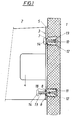
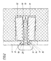
- a front panel holder 3 For attaching the front panel 1 of a drawer to a side frame 2, a front panel holder 3 is provided, which with a retaining tab in an area 4 via a fastening device permitting a height adjustment is connected to the frame 2 and holding flanges 5, 6 above and below has, in which mutually parallel, horizontal elongated holes 7, 8 are provided are. 2 shows, these slots 7, 8 have an outside wider and narrower edge with a pronounced gradation 9.
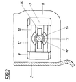
- Each expansion anchor 12 has a head part consisting of two through a gap 15 middle insertion opening 16 for the screw 13 divided flange halves 17, which, as shown in particular in FIGS. 2 and 3, snap into the gradations 9 and form longitudinal guides between dowels 12 and slot 7, 8.
- Each flange half 17 also has a comb 18 on which the head 14 of the tightened Screw 13 abuts and its outwardly sloping sides guide surfaces form.
- the expansion anchor 12 is used for preassembly with the flange halves 17 existing head section snapped into the associated slot 7, 8 from behind, which is facilitated by the mentioned guide surfaces on the combs 18. Then the expansion anchor 12 (see Fig. 1 below) is inserted or slight screwing of the screw 13, which snaps back Flange halves 17 prevents, in the preassembled position from falling out, e.g. when shipping, secured. In the final assembly, after inserting the Expansion dowels 12 in the pocket openings 10, 12 first an orientation of the Front panel 1 take place, which is then final by tightening the screws 13 is attached.
- the blind openings 10, 11 are preferably designed as blind bores, the majority of the body of the expansion dowels 12 also a corresponding one has a cylindrical basic shape.
- the introducer of each dowel 12 is also included Gap 19 from and the two dowel halves hang between the columns 15 and 19 together on relatively thin webs 20.
- the basic rectangular, the head part formed from the flanges 17 is essentially on the mentioned molded cylindrical plug body.
Landscapes
- Connection Of Plates (AREA)
- Furniture Connections (AREA)
Abstract
Description
- je einer Frontplattenhalterung an den beiden Seitenwänden oder Seitenzargen des Schubkastens, die einen zur Ermöglichung einer Seitenausrichtung mit parallelen Langlochöffnungen versehenen Flansch Stützlappen oder eine Tragplatte zur Anlage der Frontplatte aufweist,
- durch die Langlochöffnungen einführbaren Befestigungsschrauben
- und Spreizdübeln in welche die Befestigungsschrauben eingreifen und die ihrerseits in Öffnungen oder Sackbohrungen der Frontplatte oder Frontblende einführbar sind.
- Fig. 1
- eine erfindungsgemäße Vorrichtung bei im Vertikalschnitt in der Nähe einer Seitenzarge dargestellter Frontplatte mit Dübelbefestigungen, wobei bei der oberen Befestigung die Befestigungsschraube angezogen und bei der unteren Befestigung die Schraube in einer vormontierten Montagestellung dargestellt ist,
- Fig. 2
- als Detail in größerem Maßstab einen Schnitt durch Frontplatte, Frontplattenhalterung und Dübel an einer Befestigungsstelle und
- Fig. 3
- die Befestigungsstelle nach Fig. 2 bei im Schnitt dargestellter Schraube von der Einführungsseite der Schraube her.
Claims (2)
- Vorrichtung zum Befestigen einer Frontplatte oder -blende an einem Schubkasten, bestehend aus:dadurch gekennzeichnet, daß die Spreizdübel (12) drehfest mit dem übrigen Dübelkörper verbundene Kopfteile (17) aufweisen, mit denen sie von der in der Befestigungsstellung zur Frontplatte (1) weisenden Seite her in die Langlöcher (7, 8) einschnappbar sind, an diesen Kopfteilen (17) mit Führungsflanschen zum drehfesten, aber verschiebbaren Eingriff in Abstufungen (9) der Ränder der Langlöcher (7, 8) versehen sind und die Kopfteile (17) mittels der angezogenen Befestigungsschrauben (13) gegen die Öffnungswandungen der Langlochöffnungen (7, 8) festklemmbar sind.je einer Frontplattenhalterung (3) an den beiden Seitenwänden oder Seitenzargen (2) des Schubkastens, die einen zur Ermöglichung einer Seitenausrichtung mit parallelen Langlochöffnungen (7, 8) versehenen Flansch (5, 6), Stützlappen oder eine Tragplatte zur Anlage der Frontplatte (1) aufweist,durch die Langlochöffnungen (7, 8) einführbaren Befestigungsschrauben (13)und Spreizdübeln (12) in welche die Befestigungsschrauben (13) eingreifen und die ihrerseits in Öffnungen oder Sackbohrungen (10, 11) der Frontplatte (1) oder Frontblende einführbar sind,
- Vorrichtung nach Anspruch 1, dadurch gekennzeichnet, daß die Längsränder der Langlochöffnungen (7, 8) zur Bildung der Abstufungen von der Einführseite der Befestigungsschrauben (13) her von einer äußeren Verbreiterung auf eine dem Einführungsdurchmesser der Dübelkopfteile (17) entsprechende Weite abgesetzt verengt sind und in diese Abstufungen (9) eingreifende Führungsflansche oder -lappen der Kopfteile (17) der Dübel (12) durch einen Spalt (15) des Dübelkopfes voneinander abgeteilt sind, so daß sie sich beim Einschnappen in die Langlochöffnungen (7, 8) elastisch ausspreizen.
Applications Claiming Priority (2)
| Application Number | Priority Date | Filing Date | Title |
|---|---|---|---|
| AT28598 | 1998-02-18 | ||
| AT0028598A AT409708B (de) | 1998-02-18 | 1998-02-18 | Vorrichtung zum befestigen einer frontplatte oder -blende an einem schubkasten |
Publications (3)
| Publication Number | Publication Date |
|---|---|
| EP0940104A2 true EP0940104A2 (de) | 1999-09-08 |
| EP0940104A3 EP0940104A3 (de) | 2001-10-17 |
| EP0940104B1 EP0940104B1 (de) | 2003-12-17 |
Family
ID=3486491
Family Applications (1)
| Application Number | Title | Priority Date | Filing Date |
|---|---|---|---|
| EP99890024A Expired - Lifetime EP0940104B1 (de) | 1998-02-18 | 1999-01-28 | Vorrichtung zum Befestigen einer Frontplatte oder-blende an einem Schubkasten |
Country Status (4)
| Country | Link |
|---|---|
| EP (1) | EP0940104B1 (de) |
| AT (1) | AT409708B (de) |
| DE (1) | DE59908049D1 (de) |
| ES (1) | ES2214006T3 (de) |
Cited By (1)
| Publication number | Priority date | Publication date | Assignee | Title |
|---|---|---|---|---|
| AT527134A4 (de) * | 2023-07-27 | 2024-11-15 | Blum Gmbh Julius | Verbindungsvorrichtung zum Verbinden eines Wandelements einer Schubladenwand mit einem Wandprofil der Schubladenwand |
Citations (1)
| Publication number | Priority date | Publication date | Assignee | Title |
|---|---|---|---|---|
| DE3801195A1 (de) | 1988-01-18 | 1989-07-27 | Hagenhenrich Gmbh & Co Kg | Anordnung zum verbinden von schubkastenseitenzarge und -frontblende |
Family Cites Families (2)
| Publication number | Priority date | Publication date | Assignee | Title |
|---|---|---|---|---|
| US4263833A (en) * | 1979-05-15 | 1981-04-28 | Illinois Tool Works Inc. | Removable one-piece drive rivet |
| DE3717376A1 (de) * | 1987-05-22 | 1988-12-01 | Grass Alfred Metallwaren | Verstellbare grundplatte fuer scharniere |
-
1998
- 1998-02-18 AT AT0028598A patent/AT409708B/de not_active IP Right Cessation
-
1999
- 1999-01-28 ES ES99890024T patent/ES2214006T3/es not_active Expired - Lifetime
- 1999-01-28 DE DE59908049T patent/DE59908049D1/de not_active Expired - Lifetime
- 1999-01-28 EP EP99890024A patent/EP0940104B1/de not_active Expired - Lifetime
Patent Citations (1)
| Publication number | Priority date | Publication date | Assignee | Title |
|---|---|---|---|---|
| DE3801195A1 (de) | 1988-01-18 | 1989-07-27 | Hagenhenrich Gmbh & Co Kg | Anordnung zum verbinden von schubkastenseitenzarge und -frontblende |
Cited By (2)
| Publication number | Priority date | Publication date | Assignee | Title |
|---|---|---|---|---|
| AT527134A4 (de) * | 2023-07-27 | 2024-11-15 | Blum Gmbh Julius | Verbindungsvorrichtung zum Verbinden eines Wandelements einer Schubladenwand mit einem Wandprofil der Schubladenwand |
| AT527134B1 (de) * | 2023-07-27 | 2024-11-15 | Blum Gmbh Julius | Verbindungsvorrichtung zum Verbinden eines Wandelements einer Schubladenwand mit einem Wandprofil der Schubladenwand |
Also Published As
| Publication number | Publication date |
|---|---|
| AT409708B (de) | 2002-10-25 |
| ES2214006T3 (es) | 2004-09-01 |
| DE59908049D1 (de) | 2004-01-29 |
| EP0940104B1 (de) | 2003-12-17 |
| EP0940104A3 (de) | 2001-10-17 |
| ATA28598A (de) | 2002-03-15 |
Similar Documents
| Publication | Publication Date | Title |
|---|---|---|
| EP0474966B1 (de) | Befestigungsbeschlag für Schubladen-Frontblenden | |
| AT509796B1 (de) | Hohlprofil | |
| EP0761131B1 (de) | Vorrichtung zur einstellbaren Befestigung der Frontblende einer Schublade an deren Zargen | |
| DE3119571C2 (de) | ||
| EP0637213B1 (de) | Befestigungsbeschlag für schubladen-frontblenden | |
| DE3832701A1 (de) | Befestigungsanordnung fuer die fuehrungsschiene einer ausziehfuehrung | |
| EP2729037A1 (de) | Schublade | |
| DE19915913C2 (de) | Befestigungselement mit variablem Hub | |
| EP2255058B1 (de) | Aufsatz-Rollladenkasten sowie Profilsystem mit einem solchen Aufsatz-Rollladenkasten | |
| DE102018122142B4 (de) | Klemmaufnahme und Bandtasche | |
| EP3599338A1 (de) | Aufhängungsvorrichtung zur befestigung von storen | |
| DE9420726U1 (de) | Schwellenhalter für Türrahmen zur Befestigung eines Rahmenprofiles an der Türschwelle | |
| DE202007006300U1 (de) | Vorrichtung und System zur Bewegungsbeeinflussung eines Möbelteils, Montageeinrichtung für eine solche Vorrichtung und Möbel | |
| EP0940104B1 (de) | Vorrichtung zum Befestigen einer Frontplatte oder-blende an einem Schubkasten | |
| EP1764018A2 (de) | System zur Befestigung einer Platte | |
| EP2108774B1 (de) | Beschlag | |
| DE4443232C1 (de) | Befestigungseinrichtung | |
| EP1873340B1 (de) | Türanlage | |
| DE19518450A1 (de) | Möbeltür mit einem Scharnier | |
| EP1199435A2 (de) | Endstopfen zum Anschrauben von Sprossen an Abstandhalterrahmen von inbesondere Isolierglasscheiben | |
| EP2085551A2 (de) | Führungsvorrichtung für einen Schiebeflügel | |
| DE3721833C2 (de) | ||
| EP0950819A2 (de) | Befestigungsanordnung | |
| EP2562340A1 (de) | Beschlag | |
| DE29907980U1 (de) | Führungseinrichtung für Schiebetürelemente eines Möbels |
Legal Events
| Date | Code | Title | Description |
|---|---|---|---|
| PUAI | Public reference made under article 153(3) epc to a published international application that has entered the european phase |
Free format text: ORIGINAL CODE: 0009012 |
|
| AK | Designated contracting states |
Kind code of ref document: A2 Designated state(s): AT BE CH CY DE DK ES FI FR GB GR IE IT LI LU MC NL PT SE Kind code of ref document: A2 Designated state(s): DE ES IT |
|
| AX | Request for extension of the european patent |
Free format text: AL;LT;LV;MK;RO;SI |
|
| PUAL | Search report despatched |
Free format text: ORIGINAL CODE: 0009013 |
|
| AK | Designated contracting states |
Kind code of ref document: A3 Designated state(s): AT BE CH CY DE DK ES FI FR GB GR IE IT LI LU MC NL PT SE |
|
| AX | Request for extension of the european patent |
Free format text: AL;LT;LV;MK;RO;SI |
|
| 17P | Request for examination filed |
Effective date: 20011206 |
|
| AKX | Designation fees paid |
Free format text: DE ES IT |
|
| GRAP | Despatch of communication of intention to grant a patent |
Free format text: ORIGINAL CODE: EPIDOSNIGR1 |
|
| GRAS | Grant fee paid |
Free format text: ORIGINAL CODE: EPIDOSNIGR3 |
|
| GRAA | (expected) grant |
Free format text: ORIGINAL CODE: 0009210 |
|
| AK | Designated contracting states |
Kind code of ref document: B1 Designated state(s): DE ES IT |
|
| REF | Corresponds to: |
Ref document number: 59908049 Country of ref document: DE Date of ref document: 20040129 Kind code of ref document: P |
|
| REG | Reference to a national code |
Ref country code: ES Ref legal event code: FG2A Ref document number: 2214006 Country of ref document: ES Kind code of ref document: T3 |
|
| PLBE | No opposition filed within time limit |
Free format text: ORIGINAL CODE: 0009261 |
|
| STAA | Information on the status of an ep patent application or granted ep patent |
Free format text: STATUS: NO OPPOSITION FILED WITHIN TIME LIMIT |
|
| 26N | No opposition filed |
Effective date: 20040920 |
|
| REG | Reference to a national code |
Ref country code: DE Ref legal event code: R082 Ref document number: 59908049 Country of ref document: DE Representative=s name: WEICKMANN & WEICKMANN PATENT- UND RECHTSANWAEL, DE Ref country code: DE Ref legal event code: R082 Ref document number: 59908049 Country of ref document: DE Representative=s name: WEICKMANN & WEICKMANN PATENTANWAELTE - RECHTSA, DE Ref country code: DE Ref legal event code: R082 Ref document number: 59908049 Country of ref document: DE Representative=s name: PATENTANWAELTE WEICKMANN & WEICKMANN, DE |
|
| PGFP | Annual fee paid to national office [announced via postgrant information from national office to epo] |
Ref country code: DE Payment date: 20160120 Year of fee payment: 18 Ref country code: ES Payment date: 20160112 Year of fee payment: 18 Ref country code: IT Payment date: 20160127 Year of fee payment: 18 |
|
| REG | Reference to a national code |
Ref country code: DE Ref legal event code: R119 Ref document number: 59908049 Country of ref document: DE |
|
| PG25 | Lapsed in a contracting state [announced via postgrant information from national office to epo] |
Ref country code: DE Free format text: LAPSE BECAUSE OF NON-PAYMENT OF DUE FEES Effective date: 20170801 |
|
| PG25 | Lapsed in a contracting state [announced via postgrant information from national office to epo] |
Ref country code: IT Free format text: LAPSE BECAUSE OF NON-PAYMENT OF DUE FEES Effective date: 20170128 |
|
| REG | Reference to a national code |
Ref country code: ES Ref legal event code: FD2A Effective date: 20180507 |
|
| PG25 | Lapsed in a contracting state [announced via postgrant information from national office to epo] |
Ref country code: ES Free format text: LAPSE BECAUSE OF NON-PAYMENT OF DUE FEES Effective date: 20170129 |