EP0939017B1 - Übergangseinrichtung zwischen zwei gelenkig miteinander verbundenen Eisenbahnfahrzeugen - Google Patents
Übergangseinrichtung zwischen zwei gelenkig miteinander verbundenen Eisenbahnfahrzeugen Download PDFInfo
- Publication number
- EP0939017B1 EP0939017B1 EP99103524A EP99103524A EP0939017B1 EP 0939017 B1 EP0939017 B1 EP 0939017B1 EP 99103524 A EP99103524 A EP 99103524A EP 99103524 A EP99103524 A EP 99103524A EP 0939017 B1 EP0939017 B1 EP 0939017B1
- Authority
- EP
- European Patent Office
- Prior art keywords
- bridge
- arrangement according
- transfer arrangement
- transverse
- vehicle
- Prior art date
- Legal status (The legal status is an assumption and is not a legal conclusion. Google has not performed a legal analysis and makes no representation as to the accuracy of the status listed.)
- Expired - Lifetime
Links
- 239000013013 elastic material Substances 0.000 claims abstract description 7
- 239000011324 bead Substances 0.000 claims description 6
- 239000012791 sliding layer Substances 0.000 claims 1
- 239000000969 carrier Substances 0.000 abstract 2
- 238000007767 slide coating Methods 0.000 abstract 1
- 230000007704 transition Effects 0.000 description 12
- 230000000284 resting effect Effects 0.000 description 5
- 239000011248 coating agent Substances 0.000 description 2
- 238000000576 coating method Methods 0.000 description 2
- 150000001875 compounds Chemical class 0.000 description 1
- 238000010276 construction Methods 0.000 description 1
- 239000000463 material Substances 0.000 description 1
- 238000004904 shortening Methods 0.000 description 1
- 230000003319 supportive effect Effects 0.000 description 1
Images


Classifications
-
- B—PERFORMING OPERATIONS; TRANSPORTING
- B60—VEHICLES IN GENERAL
- B60D—VEHICLE CONNECTIONS
- B60D5/00—Gangways for coupled vehicles, e.g. of concertina type
- B60D5/006—Passages between articulated vehicles, e.g. bridges or rotating plates
-
- B—PERFORMING OPERATIONS; TRANSPORTING
- B61—RAILWAYS
- B61D—BODY DETAILS OR KINDS OF RAILWAY VEHICLES
- B61D17/00—Construction details of vehicle bodies
- B61D17/04—Construction details of vehicle bodies with bodies of metal; with composite, e.g. metal and wood body structures
- B61D17/20—Communication passages between coaches; Adaptation of coach ends therefor
- B61D17/22—Communication passages between coaches; Adaptation of coach ends therefor flexible, e.g. bellows
Definitions
- the invention relates to a transition device between two articulated with each other Connected railway vehicles, in particularisergliedem, with at the Vehicles held support elements for both vehicles or Vehicle links connecting bridge of rubber-elastic material, in the Cross members are poured.
- transitional devices due to the constant relative movement between the vehicles or vehicle members can not be rigid are For example, from EP-A 297 936 known.
- the from the rubber elastic Material on both sides projecting cross member are at their end with eyelets provided and threaded on support rods, which are connected to the Vehicle frame set and in their length or their mounting distance are changeable to the distance changes between the vehicles or To be able to meet vehicle parts.
- Moving the eyelets on the Support rods or the support rods in bearings on the vehicle frame requires Plain bearings, which also allow a certain rotation, resulting from the difficult conditions to which moving trains are exposed, problems arise can.
- a transition device which consists of a on a Vehicle frame rigidly mounted support plate with wide grooves defining webs and from individually movable with large intervening between the webs and on the Support plate loosely resting webs is constructed on the second vehicle frame are stored.
- the bridge is provided with a covering, which is only on a frame is attached.
- a transition device in which a plurality of steps and Slide members have bores, and on two support members relative to each other are movably and slidably threaded.
- the support elements are each at both Vehicles or vehicle parts are held displaceable.
- the aim of the invention is a continuously closed transition device without variable-length or displaceably arranged support elements. This will be done achieved in that the bridge slidably rests on two unconnected support elements of each protruding from one of the two vehicle frames. Thanks to the one-piece the resting bridge piece, it is not necessary, the support elements to connect with each other or to train continuously, but it is sufficient in the substantially uniform support of the entire bridge area.
- the undersides of the cross member exposed and provided with a sliding coating, so that the friction to the supportive support elements is low.
- the thickness of the Bridge element vary, and between the cross members has the Bridge element preferably on a smaller thickness expansion areas.
- the minimum thickness of the bridge element about 40% of maximum thickness in the area of the cross member and the edge areas amount to, where the top, so in the walking area, preferably only small troughs are formed.
- the bridge element For the attachment of the bridge element to the two vehicles or links are preferably provided at the transverse edge regions connecting elements, the have an exposed bead.
- the bead is in particular of one embraced undercut C-profile, which is fixable to the vehicle frame.
- the C-profile is composed of two sub-profiles, the connected to each other.
- each support element is computed or formed comb-like and has support webs, which are perpendicular in the longitudinal direction extend to a support bar, which is attached to the vehicle frame at the end.
- the Support webs are preferably offset from one another in the transverse direction and grip loosely into each other, so that even with a maximum cornering all cross member on the Resting overlay.
- a transition device between two articulated railway vehicles, in particular between two vehicle members of a Articulated train, has an integral bridge element 1, the two, with each other non-connected support elements 10 is slidably mounted.
- the bridge element 1 consists of a rubber-elastic material whose elasticity is so great that with a radius of curvature of 80 meters an extension of about 25% of the Normal distance is possible .
- the bridge element comprises several parallel mutually arranged cross member 3, which are cast in the material, wherein whose undersides are exposed, the like with a sliding coating 4 or the like. are occupied.
- each bead 6 is between two Partial profiles 11, 12 held by connecting screws 14 to a bead 6 enclosing, undercut C-profile are joined together.
- Each support member 10 has a on the frame 7 of the vehicle or Vehicle member attached support bar 13, at the C-profile of the Bridge element 1 is fixed by means of screws 15. From the support bar 13 extend in the longitudinal direction of the vehicle a plurality of support webs 16, whose length is about two-thirds of the width of the bridge element 1 is. Each support element 10 has therefore an approximately rake- or comb-like appearance, as the plan view in Fig. 2 shows.
- the support webs 16 are arranged offset on the two support elements 10, so that each inner support web 16 of a support element 10 between two Support webs 16 of the other support element 10 engages, wherein the support webs 16 overlap each other approximately one-third in the longitudinal direction. This will stay in Cornering with a radius of curvature of 150 m (Fig. 5) or even with a radius of curvature of 80 m ( Figure 6) a continuous support for all Cross member 3 of the bridge element 1 obtained with their sliding linings 4 on the Resting 16 resting.
- the bridge element 1 has between the cross members 3 on Dehn Anlagene 8, in where the thickness is reduced by about half, with at the top of troughs 2 with shallow depth and at the bottom grooves are provided with great depth (Fig. 4).
- the bridge element 1 is therefore both sufficiently stretchable and sufficient compressible to take the extreme position shown in Fig. 6.
- the Dehn Schemee 8 take the extension or shortening of the two frame 7th fixed bridge element 1 on, and it also results in cornering a closed, essentially level walkable floor space between the Vehicles or vehicle links.
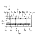
- the transition bridge consists of five transverse to the direction of travel 19 adjacent parts 1a to 1e, in operation are firmly connected to each other, so that the dividing line 20 is always closed.
- Each transition bridge part 1a to 1e includes a cross member 3a to 3e. These are all formed as hollow profiles and have an extension 17, the fits each in the subsequent part. Then, the cross member parts 3a to 3e screwed together by means of screws 18.
- the multi-part construction has a few Advantages: The parts can be supported individually. In a tearing finds the crack in any case, at the dividing line 20 its end.
- different Rubber compounds are used, for example, soft elastic outside and more stable inside.
Landscapes
- Engineering & Computer Science (AREA)
- Mechanical Engineering (AREA)
- Life Sciences & Earth Sciences (AREA)
- Wood Science & Technology (AREA)
- Vibration Prevention Devices (AREA)
- Springs (AREA)
- Motorcycle And Bicycle Frame (AREA)
- Body Structure For Vehicles (AREA)
- Road Paving Structures (AREA)
- Mechanical Control Devices (AREA)
- Automobile Manufacture Line, Endless Track Vehicle, Trailer (AREA)
- Automatic Assembly (AREA)
- Railway Tracks (AREA)
Description
Claims (13)
- Übergangseinrichtung zwischen zwei gelenkig miteinander verbundenen Eisenbahnfahrzeugen, insbesondere Fahrzeuggliedern, mit an den Fahrzeugen gehaltenen Tragelementen (10) für eine beide Fahrzeuge bzw. Fahrzeugglieder verbindende Brücke (1) aus gummielastischem Material, in die Querträger (3) eingegossen sind, dadurch gekennzeichnet, daß die Brücke (1) auf zwei unverbundenen Tragelementen (10) gleitend aufliegt, von denen jedes von einem der beiden Fahrzeugrahmen (7) absteht.
- Übergangseinrichtung nach Anspruch 1, dadurch gekennzeichnet, daß die Unterseiten der Querträger (3) freiliegen und mit einem Gleitbelag (4) versehen sind.
- Übergangseinrichtung nach Anspruch 1 oder 2, dadurch gekennzeichnet, daß die Brücke (1) zwischen den Querträgern (3) Dehnbereiche (8) mit geringer Dicke aufweist.
- Übergangseinrichtung nach einem der Ansprüche 1 bis 3, dadurch gekennzeichnet, daß die Brücke (1) in den beiden Querrandbereichen (9) parallel zu den Querträgern (3) sich erstreckende Verbindungselemente (5) aufweist.
- Übergangseinrichtung nach Anspruch 4, dadurch gekennzeichnet, daß jedes Verbindungselement (5) mit einem freiliegenden Wulst (6) versehen ist, der von einem am Fahrzeugrahmen (7) fixierbaren C-Profil umgriffen ist.
- Übergangseinrichtung nach Anspruch 5, dadurch gekennzeichnet, daß das C-Profil aus zwei miteinander verbundenen Teilprofilen (11, 12) zusammengesetzt ist.
- Übergangseinrichtung nach einem der Ansprüche 1 bis 6, dadurch gekennzeichnet, daß die Tragelemente (10) einander in Längsrichtung überlappen
- Übergangseinrichtung nach Anspruch 7, dadurch gekennzeichnet, daß jedes Tragelement (10) rechen- oder kammartig ausgebildet ist, und von einer stirnseitig am Fahrzeugrahmen (7) befestigten Tragleiste (13) senkrecht abstehende Auflagestege (16) aufweist.
- Übergangseinrichtung nach Anspruch 8, dadurch gekennzeichnet, daß beide Tragelemente (10) zueinander versetzte Auflagestege (16) aufweisen, die lose ineinandergreifen.
- Übergangseinrichtung nach einem der Ansprüche 1 bis 9, dadurch gekennzeichnet, daß die Brücke einstückig ausgebildet ist.
- Übergangseinrichtung nach einem der Ansprüche 1 bis 9, dadurch gekennzeichnet, daß die Brücke zwei- oder mehrteilig ausgebildet ist, wobei die Brückenteile (1a, 1b, 1c, 1d, 1e) im Betrieb fest miteinander verbunden sind und die Trennlinie (20) zwischen den Brückenteilen vorzugsweise in Fahrzeuglängsrichtung (19) verläuft.
- Übergangseinrichtung nach Anspruch 11, dadurch gekennzeichnet, daß die Querträger (3) unterteilt sind, wobei in jeden Brückenteil zumindest ein Querträgerteil eingegossen ist und wobei die Querträgerteile (3a, 3b, 3c, 3d, 3e) lösbar verbunden, vorzugsweise verschraubt, sind.
- Übergangseinrichtung nach Anspruch 11 oder 12, dadurch gekennzeichnet, daß das gummielastische Material der Brückenteile verschiedene Elastizitätswerte aufweist.
Priority Applications (1)
| Application Number | Priority Date | Filing Date | Title |
|---|---|---|---|
| AT99103524T ATE238935T1 (de) | 1998-02-24 | 1999-02-22 | Übergangseinrichtung zwischen zwei gelenkig miteinander verbundenen eisenbahnfahrzeugen |
Applications Claiming Priority (2)
| Application Number | Priority Date | Filing Date | Title |
|---|---|---|---|
| AT0032498A AT406568B (de) | 1998-02-24 | 1998-02-24 | Übergangseinrichtung zwischen zwei gelenkig miteinander verbundenen schienenfahrzeugen |
| AT32498 | 1998-02-24 |
Publications (3)
| Publication Number | Publication Date |
|---|---|
| EP0939017A2 EP0939017A2 (de) | 1999-09-01 |
| EP0939017A3 EP0939017A3 (de) | 2000-08-23 |
| EP0939017B1 true EP0939017B1 (de) | 2003-05-02 |
Family
ID=3487567
Family Applications (1)
| Application Number | Title | Priority Date | Filing Date |
|---|---|---|---|
| EP99103524A Expired - Lifetime EP0939017B1 (de) | 1998-02-24 | 1999-02-22 | Übergangseinrichtung zwischen zwei gelenkig miteinander verbundenen Eisenbahnfahrzeugen |
Country Status (3)
| Country | Link |
|---|---|
| EP (1) | EP0939017B1 (de) |
| AT (2) | AT406568B (de) |
| DE (1) | DE59905268D1 (de) |
Families Citing this family (2)
| Publication number | Priority date | Publication date | Assignee | Title |
|---|---|---|---|---|
| FR2865984B1 (fr) * | 2004-02-10 | 2006-05-05 | Hutchinson | Plancher pour soufflet d'interconnexion entre deux voitures |
| EP3992051B1 (de) | 2020-10-29 | 2023-08-30 | Dellner Couplers AB | Riffelblech für einen fussboden einer gangway sowie gangway |
Family Cites Families (5)
| Publication number | Priority date | Publication date | Assignee | Title |
|---|---|---|---|---|
| FR550615A (fr) * | 1923-03-26 | 1923-03-14 | Joint extensible et rétractible en tous sens pour plateformes mobiles sans solution de continuité | |
| FR2617453B1 (fr) * | 1987-07-01 | 1989-10-20 | Caoutchouc Manuf Plastique | Dispositif destine a assurer la continuite de passage entre deux vehicules successifs ferroviaires ou routiers |
| FR2724620B1 (fr) * | 1994-09-16 | 1997-01-10 | Lohr Ind | Passerelle deformable entre deux plans de chargement portes par des chassis successifs notamment ferroviaires |
| DE59500958D1 (de) | 1995-07-06 | 1997-12-11 | Huebner Gummi & Kunststoff | Gliederbrücke |
| FR2759635B1 (fr) * | 1997-02-20 | 1999-04-16 | Hutchinson | Plancher elastique destine notamment a un soufflet de passage |
-
1998
- 1998-02-24 AT AT0032498A patent/AT406568B/de not_active IP Right Cessation
-
1999
- 1999-02-22 EP EP99103524A patent/EP0939017B1/de not_active Expired - Lifetime
- 1999-02-22 DE DE59905268T patent/DE59905268D1/de not_active Expired - Lifetime
- 1999-02-22 AT AT99103524T patent/ATE238935T1/de not_active IP Right Cessation
Also Published As
| Publication number | Publication date |
|---|---|
| DE59905268D1 (de) | 2003-06-05 |
| AT406568B (de) | 2000-06-26 |
| ATE238935T1 (de) | 2003-05-15 |
| ATA32498A (de) | 1999-11-15 |
| EP0939017A3 (de) | 2000-08-23 |
| EP0939017A2 (de) | 1999-09-01 |
Similar Documents
| Publication | Publication Date | Title |
|---|---|---|
| EP0391149B2 (de) | Verlegbare Brücke und System zum Verlegen der Brücke | |
| DE3305062C2 (de) | ||
| DE4306040A1 (de) | Verfahren und Vorrichtung zum Querverschub von überhöht hergestellten Brückenbauteilen | |
| DE69301689T2 (de) | Fördereinrichtung mit variabler Geschwindigkeit für beschleunigte Personenfahrbänder | |
| EP0257185B1 (de) | Übergangsbrücke für eine Übergangseinrichtung | |
| DE3505470C2 (de) | ||
| EP0215980A1 (de) | Lamellenübergang für Dehnfugen an Brücken o. dgl. | |
| DE69510860T2 (de) | Bodenplatteneinrichtung für eine Übergangsbrücke zwischen Fahrzeugen | |
| AT406568B (de) | Übergangseinrichtung zwischen zwei gelenkig miteinander verbundenen schienenfahrzeugen | |
| EP1114221B1 (de) | Schwellenrahmen für eine gleisanlage für schienengebundene fahrzeuge, insbesondere für einen schotteroberbau | |
| EP0145667B1 (de) | Ueberbrückungs-Vorrichtung für Dehnfugen in Fahrbahnen von Brücken oder dergleichen | |
| DE2432548A1 (de) | Herzstueck sehr grosser laenge fuer gleisanlagen fuer sehr grosse verkehrsgeschwindigkeiten | |
| EP0988424A1 (de) | Modulare brücke | |
| DE10221627A1 (de) | Fahrweg für eine Magnetschwebebahn | |
| DE4239882A1 (de) | Spurgebundenes Fahrzeug | |
| EP1232084B1 (de) | Hauptquerträger für schienenfahrzeuge in aluminium-grossprofil-bauweise | |
| DE2615836C2 (de) | Auflagerkonstruktion für Brückenträger | |
| DE102015214747A1 (de) | Übergangseinrichtung für Schienenfahrzeuge | |
| DE2905888C2 (de) | Vorrichtung zum Überbrücken von Dehnungsfugen | |
| DE3536499C2 (de) | ||
| EP1063353B1 (de) | Gleisabschnitt mit Weiche | |
| AT395131B (de) | Ladebordwand fuer ein lastfahrzeug | |
| DE3019594A1 (de) | Fugenueberbrueckung fuer dehnfugen in bruecken o.dgl. | |
| DE20205223U1 (de) | Kran | |
| DE3417129C2 (de) | Übergangsschutz zum lösbaren Einbau zwischen zwei aufeinanderfolgenden, gelenkig miteinander verbundenen Fahrzeuggliedern |
Legal Events
| Date | Code | Title | Description |
|---|---|---|---|
| PUAI | Public reference made under article 153(3) epc to a published international application that has entered the european phase |
Free format text: ORIGINAL CODE: 0009012 |
|
| AK | Designated contracting states |
Kind code of ref document: A2 Designated state(s): AT BE CH DE ES FR GB IT LI NL SE |
|
| AX | Request for extension of the european patent |
Free format text: AL;LT;LV;MK;RO;SI |
|
| PUAL | Search report despatched |
Free format text: ORIGINAL CODE: 0009013 |
|
| AK | Designated contracting states |
Kind code of ref document: A3 Designated state(s): AT BE CH CY DE DK ES FI FR GB GR IE IT LI LU MC NL PT SE |
|
| AX | Request for extension of the european patent |
Free format text: AL;LT;LV;MK;RO;SI |
|
| 17P | Request for examination filed |
Effective date: 20000907 |
|
| AKX | Designation fees paid |
Free format text: AT BE CH DE ES FR GB IT LI NL SE |
|
| RAP1 | Party data changed (applicant data changed or rights of an application transferred) |
Owner name: CONNEX VERKEHR GMBH |
|
| GRAH | Despatch of communication of intention to grant a patent |
Free format text: ORIGINAL CODE: EPIDOS IGRA |
|
| GRAH | Despatch of communication of intention to grant a patent |
Free format text: ORIGINAL CODE: EPIDOS IGRA |
|
| GRAA | (expected) grant |
Free format text: ORIGINAL CODE: 0009210 |
|
| AK | Designated contracting states |
Designated state(s): AT BE CH DE ES FR GB IT LI NL SE |
|
| PG25 | Lapsed in a contracting state [announced via postgrant information from national office to epo] |
Ref country code: NL Free format text: LAPSE BECAUSE OF FAILURE TO SUBMIT A TRANSLATION OF THE DESCRIPTION OR TO PAY THE FEE WITHIN THE PRESCRIBED TIME-LIMIT Effective date: 20030502 Ref country code: GB Free format text: LAPSE BECAUSE OF FAILURE TO SUBMIT A TRANSLATION OF THE DESCRIPTION OR TO PAY THE FEE WITHIN THE PRESCRIBED TIME-LIMIT Effective date: 20030502 |
|
| REG | Reference to a national code |
Ref country code: GB Ref legal event code: FG4D Free format text: NOT ENGLISH |
|
| REG | Reference to a national code |
Ref country code: CH Ref legal event code: EP |
|
| REF | Corresponds to: |
Ref document number: 59905268 Country of ref document: DE Date of ref document: 20030605 Kind code of ref document: P |
|
| PG25 | Lapsed in a contracting state [announced via postgrant information from national office to epo] |
Ref country code: SE Free format text: LAPSE BECAUSE OF FAILURE TO SUBMIT A TRANSLATION OF THE DESCRIPTION OR TO PAY THE FEE WITHIN THE PRESCRIBED TIME-LIMIT Effective date: 20030802 |
|
| PG25 | Lapsed in a contracting state [announced via postgrant information from national office to epo] |
Ref country code: ES Free format text: LAPSE BECAUSE OF FAILURE TO SUBMIT A TRANSLATION OF THE DESCRIPTION OR TO PAY THE FEE WITHIN THE PRESCRIBED TIME-LIMIT Effective date: 20030813 |
|
| REG | Reference to a national code |
Ref country code: CH Ref legal event code: NV Representative=s name: INTERPAT LAW AG |
|
| NLV1 | Nl: lapsed or annulled due to failure to fulfill the requirements of art. 29p and 29m of the patents act | ||
| GBV | Gb: ep patent (uk) treated as always having been void in accordance with gb section 77(7)/1977 [no translation filed] |
Effective date: 20030502 |
|
| PG25 | Lapsed in a contracting state [announced via postgrant information from national office to epo] |
Ref country code: AT Free format text: LAPSE BECAUSE OF NON-PAYMENT OF DUE FEES Effective date: 20040222 |
|
| PG25 | Lapsed in a contracting state [announced via postgrant information from national office to epo] |
Ref country code: BE Free format text: LAPSE BECAUSE OF NON-PAYMENT OF DUE FEES Effective date: 20040228 |
|
| PLBE | No opposition filed within time limit |
Free format text: ORIGINAL CODE: 0009261 |
|
| STAA | Information on the status of an ep patent application or granted ep patent |
Free format text: STATUS: NO OPPOSITION FILED WITHIN TIME LIMIT |
|
| ET | Fr: translation filed | ||
| 26N | No opposition filed |
Effective date: 20040203 |
|
| BERE | Be: lapsed |
Owner name: *CONNEX VERKEHR G.M.B.H. Effective date: 20040228 |
|
| REG | Reference to a national code |
Ref country code: CH Ref legal event code: PCAR Free format text: ISLER & PEDRAZZINI AG;POSTFACH 1772;8027 ZUERICH (CH) |
|
| PG25 | Lapsed in a contracting state [announced via postgrant information from national office to epo] |
Ref country code: IT Free format text: LAPSE BECAUSE OF NON-PAYMENT OF DUE FEES Effective date: 20070222 |
|
| PGFP | Annual fee paid to national office [announced via postgrant information from national office to epo] |
Ref country code: CH Payment date: 20100204 Year of fee payment: 12 |
|
| PGFP | Annual fee paid to national office [announced via postgrant information from national office to epo] |
Ref country code: FR Payment date: 20100305 Year of fee payment: 12 |
|
| PGFP | Annual fee paid to national office [announced via postgrant information from national office to epo] |
Ref country code: DE Payment date: 20100421 Year of fee payment: 12 |
|
| PGFP | Annual fee paid to national office [announced via postgrant information from national office to epo] |
Ref country code: IT Payment date: 20100222 Year of fee payment: 12 |
|
| PGRI | Patent reinstated in contracting state [announced from national office to epo] |
Ref country code: IT Effective date: 20110616 |
|
| REG | Reference to a national code |
Ref country code: CH Ref legal event code: PL |
|
| PG25 | Lapsed in a contracting state [announced via postgrant information from national office to epo] |
Ref country code: CH Free format text: LAPSE BECAUSE OF NON-PAYMENT OF DUE FEES Effective date: 20110228 Ref country code: LI Free format text: LAPSE BECAUSE OF NON-PAYMENT OF DUE FEES Effective date: 20110228 |
|
| REG | Reference to a national code |
Ref country code: FR Ref legal event code: ST Effective date: 20111102 |
|
| PGRI | Patent reinstated in contracting state [announced from national office to epo] |
Ref country code: IT Effective date: 20110616 |
|
| REG | Reference to a national code |
Ref country code: DE Ref legal event code: R119 Ref document number: 59905268 Country of ref document: DE Effective date: 20110901 |
|
| PG25 | Lapsed in a contracting state [announced via postgrant information from national office to epo] |
Ref country code: FR Free format text: LAPSE BECAUSE OF NON-PAYMENT OF DUE FEES Effective date: 20110228 |
|
| PG25 | Lapsed in a contracting state [announced via postgrant information from national office to epo] |
Ref country code: DE Free format text: LAPSE BECAUSE OF NON-PAYMENT OF DUE FEES Effective date: 20110901 |