EP0938760B1 - Elktrischer rollkontaktgeber - Google Patents
Elktrischer rollkontaktgeber Download PDFInfo
- Publication number
- EP0938760B1 EP0938760B1 EP98940842A EP98940842A EP0938760B1 EP 0938760 B1 EP0938760 B1 EP 0938760B1 EP 98940842 A EP98940842 A EP 98940842A EP 98940842 A EP98940842 A EP 98940842A EP 0938760 B1 EP0938760 B1 EP 0938760B1
- Authority
- EP
- European Patent Office
- Prior art keywords
- arm
- rolling
- contactor
- holder
- housing
- Prior art date
- Legal status (The legal status is an assumption and is not a legal conclusion. Google has not performed a legal analysis and makes no representation as to the accuracy of the status listed.)
- Expired - Lifetime
Links
- 238000005096 rolling process Methods 0.000 title claims description 36
- 238000004891 communication Methods 0.000 claims description 7
- 230000000284 resting effect Effects 0.000 claims 10
- 210000002105 tongue Anatomy 0.000 claims 4
- 238000012360 testing method Methods 0.000 abstract description 14
- 239000000463 material Substances 0.000 abstract description 7
- 229910001369 Brass Inorganic materials 0.000 abstract description 6
- 239000010951 brass Substances 0.000 abstract description 6
- 239000003985 ceramic capacitor Substances 0.000 abstract description 5
- 230000000712 assembly Effects 0.000 abstract description 3
- 238000000429 assembly Methods 0.000 abstract description 3
- 230000007246 mechanism Effects 0.000 abstract description 2
- 239000012858 resilient material Substances 0.000 abstract 1
- 238000005259 measurement Methods 0.000 description 5
- 239000000470 constituent Substances 0.000 description 4
- 238000000034 method Methods 0.000 description 4
- 229910000831 Steel Inorganic materials 0.000 description 3
- 230000008901 benefit Effects 0.000 description 3
- 238000007747 plating Methods 0.000 description 3
- 229910000679 solder Inorganic materials 0.000 description 3
- 239000010959 steel Substances 0.000 description 3
- OKTJSMMVPCPJKN-UHFFFAOYSA-N Carbon Chemical compound [C] OKTJSMMVPCPJKN-UHFFFAOYSA-N 0.000 description 2
- RYGMFSIKBFXOCR-UHFFFAOYSA-N Copper Chemical compound [Cu] RYGMFSIKBFXOCR-UHFFFAOYSA-N 0.000 description 2
- ATJFFYVFTNAWJD-UHFFFAOYSA-N Tin Chemical compound [Sn] ATJFFYVFTNAWJD-UHFFFAOYSA-N 0.000 description 2
- 230000004323 axial length Effects 0.000 description 2
- 238000004140 cleaning Methods 0.000 description 2
- 239000002131 composite material Substances 0.000 description 2
- 239000004020 conductor Substances 0.000 description 2
- 229910052802 copper Inorganic materials 0.000 description 2
- 239000010949 copper Substances 0.000 description 2
- 229910002804 graphite Inorganic materials 0.000 description 2
- 239000010439 graphite Substances 0.000 description 2
- 238000009434 installation Methods 0.000 description 2
- 229910052751 metal Inorganic materials 0.000 description 2
- 239000004593 Epoxy Substances 0.000 description 1
- 230000009471 action Effects 0.000 description 1
- 229910052782 aluminium Inorganic materials 0.000 description 1
- XAGFODPZIPBFFR-UHFFFAOYSA-N aluminium Chemical compound [Al] XAGFODPZIPBFFR-UHFFFAOYSA-N 0.000 description 1
- 239000000356 contaminant Substances 0.000 description 1
- 230000003247 decreasing effect Effects 0.000 description 1
- 230000007547 defect Effects 0.000 description 1
- 230000000694 effects Effects 0.000 description 1
- 230000008030 elimination Effects 0.000 description 1
- 238000003379 elimination reaction Methods 0.000 description 1
- 239000011521 glass Substances 0.000 description 1
- PCHJSUWPFVWCPO-UHFFFAOYSA-N gold Chemical compound [Au] PCHJSUWPFVWCPO-UHFFFAOYSA-N 0.000 description 1
- 239000010931 gold Substances 0.000 description 1
- 229910052737 gold Inorganic materials 0.000 description 1
- 230000006872 improvement Effects 0.000 description 1
- 238000004519 manufacturing process Methods 0.000 description 1
- 239000002184 metal Substances 0.000 description 1
- 239000007769 metal material Substances 0.000 description 1
- 239000000203 mixture Substances 0.000 description 1
- 238000012986 modification Methods 0.000 description 1
- 230000004048 modification Effects 0.000 description 1
- 239000012811 non-conductive material Substances 0.000 description 1
- 230000003647 oxidation Effects 0.000 description 1
- 238000007254 oxidation reaction Methods 0.000 description 1
- 238000012545 processing Methods 0.000 description 1
- 230000008707 rearrangement Effects 0.000 description 1
- 239000007787 solid Substances 0.000 description 1
Images


Classifications
-
- H—ELECTRICITY
- H01—ELECTRIC ELEMENTS
- H01R—ELECTRICALLY-CONDUCTIVE CONNECTIONS; STRUCTURAL ASSOCIATIONS OF A PLURALITY OF MUTUALLY-INSULATED ELECTRICAL CONNECTING ELEMENTS; COUPLING DEVICES; CURRENT COLLECTORS
- H01R39/00—Rotary current collectors, distributors or interrupters
- H01R39/02—Details for dynamo electric machines
- H01R39/18—Contacts for co-operation with commutator or slip-ring, e.g. contact brush
- H01R39/28—Roller contacts; Ball contacts
-
- H—ELECTRICITY
- H01—ELECTRIC ELEMENTS
- H01H—ELECTRIC SWITCHES; RELAYS; SELECTORS; EMERGENCY PROTECTIVE DEVICES
- H01H1/00—Contacts
- H01H1/12—Contacts characterised by the manner in which co-operating contacts engage
- H01H1/14—Contacts characterised by the manner in which co-operating contacts engage by abutting
- H01H1/16—Contacts characterised by the manner in which co-operating contacts engage by abutting by rolling; by wrapping; Roller or ball contacts
-
- H—ELECTRICITY
- H01—ELECTRIC ELEMENTS
- H01H—ELECTRIC SWITCHES; RELAYS; SELECTORS; EMERGENCY PROTECTIVE DEVICES
- H01H1/00—Contacts
- H01H2001/001—Contacts providing easy replacement of contacts
Definitions
- This invention relates in general to the field of cantilever type electrical contactors, and more particularly to those that wipe (as "wipe” is defined below) across an opposing contact area while making contact therewith.
- a cantilever type contactor typically has a flat spring metal arm which is canted or angled with respect to a device to be contacted. At the free end of the arm is a contact point. A contacting area of the device to be contacted is moved, actually or relatively, such that the contact point rubs, i.e. wipes, against the area and the cantilever arm is deflected slightly. Due to the spring in the arm it applies pressure on the contact area, sufficient pressure for good electrical contact.
- This wiping technique can use one cantilever arm and one stationary contact point, or two cantilever arms.
- the wiping method although simple and reliable, has certain drawbacks.
- the cantilever contact tip being relatively stationary, wipes across the entire exposed length of the device termination, creating a relatively large mark on the termination, and greatly increasing the chances of termination damage.
- the cantilever tips periodically come into contact with the holding fixture. Since the cantilever tip is relatively stationary, it is abraded by the test fixture material, which is typically FR-4 glass epoxy, or a similar non-conductive material, which tends to have a moderate or high abrasive quality. The cantilever tips become rough from this contact and tend to further damage the device terminations. Also the contactor tips become dirty, either by oxidation or adherence of contaminants to the contact tips, or a combination of both. Access to the contact tips for cleaning is difficult due to the close proximity of the contact tips to the devices measured and the device holding fixture(s).
- the actuated contactor technique uses moving contact tips, usually in a reciprocating motion, which are brought into contact with the devices.
- the contact tips are actuated for each test cycle, moved until they make contact with the device, then held stationary during the measurement of the device. After the measurement, the contacts are moved away from the device, and the device's holding plate or fixture is indexed, bringing the next device into position for the subsequent measurement.
- Actuated contacts can be made with very small tip sizes in order to reduce any marking of the termination ends of the tested device, unlike the wiping contact technique. Due to the high throughputs of production testing equipment, however, this actuation cycle must be done at very high speed and at rapid rates.
- a component tester such as the Palomar Model 3300 would require 37,500 contactor actuation cycles per hour, running 150,000 parts per hour. If the components used for the actuation mechanism lasted 30,0.00, 000 cycles, they would have to be replaced every 40 days; assuming 20 hours of machine run time per day. If the actuation time was only 10ms in each actuation direction, the system throughput would be decreased by 10,000 parts per hour as well. Actuated contacts can also push or pull the device out of its holding plate/fixture, and the contact tips tend to be more expensive, requiring moving or flexible electrically conductive components, such as gold plated springs, or very flexible wire segments.
- the contactor of this invention will allow rapid and repeated electrical connection to the terminations of many types of devices with little or no damage or markings.
- the electrical contactor according to this invention is a significant advance over the prior art. It eliminates the damage done to the solder plating on the terminations of devices due to the "wiping" action of the cantilever type contactors and is simpler and has a longer life than the actuated type contactor. It is particularly useful in component handlers and testers for the processing and testing of electrical circuit components, for example ceramic capacitors.
- US 5,470,260 relates to an electrical connector for connecting to conducting circuit traces on a card, including contact wheels rotatably mounted on resilient cantilever arms.
- An object of this invention is to provide a contactor which will not damage the terminations of small electronic devices while making contact therewith.
- An additional object of this invention is to provide a contactor having a rolling point of contact.
- An additional object of this invention is to provide a contactor having a rolling point of contact mounted on a resilient arm.
- An additional object of this invention is to provide a contact having a rolling point of contact which is easily removable from a resilient arm.
- An additional object of this invention is to provide a contact having a rolling point of contact which is reliable.
- An additional object of this invention is to provide a contact having a rolling point of contact which has a long life.
- An additional object of this invention is to provide a contact having a rolling point of contact which is narrow enough to allow multiple contacts to fit into a testing module for testing multiple electronic devices.
- An additional object of this invention is to provide a multiple contactor module for holding a plurality of contactors for simultaneously making electrical measurements on small electronic devices.
- An additional object of this invention is to provide a multiple contactor module for holding a plurality of contactors to provide electrical continuity from the contactor arm to the module.
- An additional object of this invention is to provide a multiple contactor module for holding a plurality of contactors and having an open position to allow the easy removal and replacement of the contactors in the module.
- An additional object of this invention is to provide a multiple contactor module for holding a plurality of contactors having a positive means of locating the position of the contactors in the module.
- a rolling contactor for providing electrical signal communication between a component terminal and a support structure, comprising (1) an electrically conductive roller for making rolling contact with the component terminal, (2) a holding module connectable to the support structure and in signal communication therewith, and (3) a resilient arm for cantilevering the roller from the holding module, the arm including a path for communicating signals between the roller and the holding module.
- the roller is preferably brass or other highly conductive, durable material for repeatedly making sound electrical contact with component terminals (for example, terminations of ceramic capacitors).
- the arm is preferably made from a highly conductive material to communicate signals between the roller and the holder.
- roller/cantilever arm assemblies connected in parallel to the holding module, preferably with the rollers aligned, to make simultaneous contact with a plurality of components, or component terminals.
- the holding module is secured to a structure (for example, a test jig of a component handler), and provides respective signal communication paths between each roller/cantilever arm assembly and the electronics of the structure (for example, a computer interface of a component handler).
- the roller/cantilever arm assemblies are easily disconnectable from their holders so they can be quickly replaced when needed.
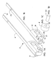
- the contactor of the preferred embodiment of this invention is generally designated as 2 and consists of a rotatable contact wheel, or "roller” 4 supported by an elongated cantilever arm 6.
- the arm is symmetrical about its longitudinal axis and has a contact or tip end 8 and a plug end 10.
- a pair of parallel, symmetrical flanges 12 project orthogonally from opposite sides of the arm at its tip end.
- the arm is of uniform rectangular cross-section except for a slight taper at the plug end.
- Each flange is partially bifurcated by a narrow slit 16 running parallel to the arm 6, the slit being open at the tip end and intersecting a circular strain relief hole 18 defined by and at the rear of the flange.
- the slit and relief hole create a lower resilient prong 20.
- Opposing semi-circular cutouts, 21 and 22, are defined respectively on opposite sides of the slit near the tip end, the cutouts being aligned to receive respective ends of an axle 24 of the roller 4.
- the open ends of the slits are tapered to allow the axle to be pressed into the slit, causing the prongs to flex downward, and to be pressed further into the cutouts. Once in the cutouts the axle is held firmly by the prongs so that it does not rotate.
- a locating hole 26 is defined by the arm intermediate the arm's tip and its plug end.
- the roller 4 is cylindrical in shape for rolling and preferably comprises a solid piece of brass or similarly highly conductive and durable material to make electrical contact with a device termination.
- the roller has an axial length slightly less than the gap between the flanges 12 to allow it to roll on its axle 24 freely.
- the roller defines an axial hole 30 sized to allow the roller to turn freely on its axle.
- the axle preferably comprises copper impregnated graphite or similar material to provide electrical contact between the roller and the flanges 12 of the arm.
- the composition of the roller also provides a lubricated surface for the roller.
- An advantage of the preferred embodiment is that the configuration of the flanges allows the rollers, and their axles, to be easily replaced. When, due to wear or defects, a roller or axle needs to be replaced, it can easily be forcibly pulled out of the slit and replaced.
- the rolling contact is also an improvement over the cantilever wiping contact because it is more easily cleaned. Since the roller's contacting surface is continually exposed, it is easily accessible for cleaning, unlike a typical cantilever contact tip.
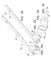
- the contactor of a second embodiment of this invention is generally designated as 32 and also consists of a rotatable wheel, or "roller” 34 supported by an elongated cantilever arm 36.
- the arm is symmetrical about its longitudinal axis and has a contact or tip end 38 and a plug end 40.
- a pair of parallel, symmetrical flanges 42 project orthogonally from opposite sides of the arm at its tip end.
- the arm is of uniform rectangular cross-section except for a slight taper at its plug end.
- the flanges each define a hole 44, the holes being aligned for journaling respective ends of an axle 46.
- a locating hole 26 is defined by the arm intermediate the arm's tip and its plug end.
- the roller has an annular sleeve 48 and a cylindrical core 50 over which the sleeve is frictionally fitted, e.g. press-fitted.
- the sleeve is the part of the roller that makes physical and electrical contact with the termination of a target device.
- the core 50 is thick-walled, relative to the sleeve, and has the same axial length.
- the axle 46 is press fitted into the axial hole 51 defined by the core. All these frictional fittings create a roller assembly having a tight, frictional, non-slip fit between all its constituent parts.
- the axle can be press-fitted into the core after the core with sleeve have been installed between the parallel flanges 42.
- the annular sleeve preferably comprises brass or other highly conductive and durable metal or composite material.
- the core is preferably made of a highly conductive composite material such as copper impregnated graphite.
- the axle is made of a highly conductive and durable material such as brass. The axle is in electrical contact with the flange of the arm, and thus there is electrical continuity between the sleeve and the contactor arm.
- the contactors of Figs. 1A-1D and 2A-2E can be installed in parallel into a module 52 for contacting multiple devices (not shown) at a time.
- a module 52 for contacting multiple devices (not shown) at a time.
- the module 52 is illustrated to be secured to a support structure 54 such as a test handler jig, not fully shown.
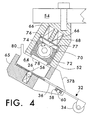
- the plurality of cantilever contactors 32 are held longitudinally in place in the module 52 by means of a spring-biased locator ball 56 which seats in a hole 26 defined by the contactor's arm 36.
- the lateral alignment of the contactors 32 is accomplished by a positioning bar 58 which is supported between two forward projections, 57A and 57B, of the module by a support rod 60.
- the positioning bar made of a polycarbonite material, has a plurality of lateral grooves 62, as best shown in Figure 5 , perpendicular to the support rod and each having a width to accommodate the arm 36 of a contactor. As illustrated there are four grooves in the positioning bar and four contactors in the multiple contactor module. However, the module could be adapted to use fewer or more than four contactors depending on the testing requirements.
- the multiple contactor module is shown in its closed position. In this position the contactor arms are securely held in the module by corresponding contact blocks 64. In operation, the contact blocks are pressed against a corresponding contactor arm pinning it against a non-conductive, flat base 65 of the module.
- the contact blocks are preferably gold-plated brass for maximum electrical conductivity, although they may comprise other physically rigid, highly conductive materials as well.
- the contact blocks are pressed against their corresponding arms by a strong clamping force supplied by two clamp springs 66 disposed in spring sockets defined by an upper housing of the module.
- the clamp springs react against a preferably aluminum clamp block 70 disposed in a hole defined by the module housing, the clamp block being moveable within its hole over a range to and from the contact blocks.
- the clamp springs urge the clamp block toward the plurality of contact blocks.
- a non-conductive elastomeric (e.g. rubber, or rubber-like) pad 78 Between the clamp block and the contact blocks is a non-conductive elastomeric (e.g. rubber, or rubber-like) pad 78, and so the clamp block presses against the pad which in turn presses against the contact blocks, thus transferring the clamp spring force to the contactor arms to clamp them in place.
- a preferably steel cam shaft 72 extends through an elongated channel 74 defined by the clamp block, the channel running orthogonal to the contact blocks.
- One end of the cam shaft is journaled for turning in the module housing, the other end being exposed and defining a wrench socket.
- a preferably steel cam pin 76 is seated in a longitudinal, perimetric groove defined by the cam shaft immediately adjacent a cam shaft flat 77, the cam pin radially projecting beyond the perimeter of the shaft.
- the channel is cylindrical except for a flat side which generally faces the flat of the cam shaft. Except for its flat side, the channel is wide enough to accommodate the projecting cam pin.
- the channel's flat side is defined by a preferably steel cam plate 68 which is embedded in the clamp block 70 and which intersects the channel.
- the clamp plate functions as a hard flat side of the channel against which the hard cam pin acts.
- the cam shaft is rotated to the point at which the cam pin encounters the cam plate, further rotation will drive the cam pin against the cam plate causing the plate to move, and when it moves it causes the clamp block 70 to move away from the contact blocks.
- This removes the contactor arm clamping force allowing them to be inserted, removed, or replaced, whatever the case may be.
- the cam shaft is turned the opposite way to an extent that the cam pin is no longer acting against the cam plate.
- the clamping force and the high conductivity of the contact block provides electrical continuity between the contactor arms 36, and thus the rollers 34, and the terminals 80 of corresponding clamp blocks 64.
- the embodiments described above can be used in an arrangement in which the contactors of this invention make contact with one of the terminals of a component, e.g. one end of a surface mount ceramic capacitor, with the other terminal being contacted by a stationary contact.
- rolling contactors can be used for contacting both of the terminals, depending on the arrangement of the test handler.
- multiple contact modules could be constructed to allow two contactors, in close proximity, to make contact with a single terminal of the device being tested.
- the other terminal of the electrical device could also be contacted by either stationary contacts or also by one or two rolling contacts.
- Another advantage of a rolling contact is the elimination of the "tiddly wink" effect that can occur when a cantilever wiping contact passes over a device being tested.
- the cantilever contact applies pressure as it tests the terminal of the device and as the device is rotated from under the cantilever contact the pressure is abruptly lost and can cause the device to snap out of the module. This is similar to a tiddly wink being snapped by the pressure abruptly being lost from an edge of the tiddly wink. With a rolling contact, the pressure is not abruptly lost and there is no "tiddly winking.”
Landscapes
- Measuring Leads Or Probes (AREA)
- Testing Of Individual Semiconductor Devices (AREA)
- Rolls And Other Rotary Bodies (AREA)
- Treatments Of Macromolecular Shaped Articles (AREA)
- Reduction Rolling/Reduction Stand/Operation Of Reduction Machine (AREA)
- Conductive Materials (AREA)
- Contacts (AREA)
- Thermally Actuated Switches (AREA)
- Testing Electric Properties And Detecting Electric Faults (AREA)
Claims (12)
- Schütz (2, 32) zur Bereitstellung der Kommunikation eines elektrischen Signals zwischen einem Bauteilanschluss und einer Stützstruktur (54) für das Schütz (2, 32), worin der Bauteilanschluss ein Bauteilanschluss einer elektronischen Miniaturvorrichtung ist und das Schütz ein federnd einseitig gelagertes Rollkontaktschütz ist, das Folgendes umfasst:a) ein elektrisch leitfähiges Mittel, das über den Bauteilanschluss rollt, um ein oder mehrere Signale zu kommunizieren, wobei das Rollmittel Folgendes umfasst:i) eine zylindrische elektrisch leitfähige Walze (4, 24; 34, 46) undii) deren Achse (24, 46);b) eine Haltevorrichtung (64, 52), die an die Stützstruktur (54) anschließbar ist und mit dieser in Signalkommunikation steht; undc) ein Mittel (6, 10; 36, 40), um das Rollmittel (4, 24; 34, 46) von der Haltevorrichtung (64, 52) aus federnd einseitig zu lagern, damit dieses sich in Reaktion auf eine Ablenkung des Rollmittels (4, 24; 34, 46) durch ein Bauteil biegt, wobei das Mittel zur federnden einseitigen Lagerung (6, 10; 36, 40) Mittel zur Kommunikation von Signalen zwischen dem Rollmittel und der Haltevorrichtung (64, 52) umfasst und Folgendes umfasst:i) einen länglichen Arm (6, 36), wobei dieser elektrisch leitfähig ist, um eine Signalkommunikation zwischen dem Rollmittel und der Haltevorrichtung (64, 52) herzustellen;ii) Mittel zum elektrischen und mechanischen Verbinden des Arms (6, 36) an einem Ende (10, 40) mit der Haltevorrichtung (64, 52), wobei die Haltevorrichtung (64, 52) Folgendes umfasst:(1) ein Basismittel (65) zur Bereitstellung eines Platzes, an dem das eine, von dem Rollmittel entfernte, Ende (10, 40) des Arms (6, 36) ruht; und(2) ein Mittel zur Positionierung (58, 62; 26, 56) des Arms (6, 36) in Längsrichtung und seitlicher Richtung, um ihn in seine Ruheposition zu bringen; undiii) ein Mittel zum elektrischen und mechanischen Verbinden des Arms (6, 36) mit dem Rollmittel an einem entgegengesetzten Ende (8, 38) des länglichen Arms (6, 36), die Folgendes umfasst:(1) ein Paar Flansche (12; 42), die von entgegengesetzten Seiten des Arms (6, 36) an dem entgegengesetzten Ende (8, 38) im rechten Winkel abstehen; und(2) ein Paar fluchtend ausgerichteter Löcher (21, 22; 44), die durch die Flansche (12; 42) definiert sind, um Enden der Achse (24, 46) zu lagern, wobei die Achse (24, 46) normal zu dem Arm (6, 36) angeordnet ist.
- Schütz (2, 32) nach Anspruch 1, das ferner Folgendes umfasst:a) ein Gehäuse (52), wobei das Basismittel (65) in das Gehäuse (52) integriert ist;b) ein Paar Zungen (57A, 57B), die parallel zu dem Arm (6, 36) von entegegengesetzten Seiten des Gehäuses (52) in Richtung des Rollmittels (4, 24; 34, 46) vorstehen; undc) ein Anschlagmittel (58), das sich zwischen den Zungen (57A, 57B) zwischen dem Gehäuse (52) und dem Rollmittel (4, 24; 34, 46) erstreckt, um die Bewegung des Arms (6, 36) in Richtung eines Bauteils einzuschränken.
- Schütz (2, 32) nach Anspruch 2, worin das Mittel zur Positionierung (58, 62; 26, 56) Folgendes umfasst:a) eine Begrenzungsnut (62), in der der Arm (6, 36) angeordnet ist, um eine seitliche Bewegung (6, 36) des Arms zu verhindern, wobei die Nut (62) durch gegenüberliegende Rippen definiert ist, die von dem Anschlagmittel (58) vorstehen;b) ein Loch (26), das durch den Arm (6, 36) in dem eingespannten Teil des Arms (6, 36) definiert ist;c) durch eine Feder vorgespannte Arretierungsmittel (56), die in das Basismittel (65) integriert sind, um mit dem Loch (26) in dem Arm (6, 36) in Eingriff zu gelangen.
- Schütz (2, 32) nach Anspruch 1, das ferner Folgendes umfasst:lösbare Klemmmittel (70, 64), die dem Basismittel (65) entgegenwirken, um den Arm (6, 36) in seiner Ruheposition zu halten.
- Schütz (2, 32) nach Anspruch 4, worin das Klemmmittel (70, 64) Folgendes umfasst:a) eine Klemmbacke (64, 70, 78), die in der Ruheposition des Arms (6, 36) auf diesen zu oder von diesem weg bewegbar ist; undb) ein mittels einer Feder vorgespanntes Nockenmittel (72), das in dem Gehäuse (52) gelagert ist, um die Klemmbacke (64, 70, 78) selektiv auf den Arm (6, 36) zu oder von diesem weg zu bewegen.
- Schütz (2, 32) nach Anspruch 5, worin die Klemmbacke (64, 70, 78) Folgendes umfasst:a) ein leitfähiges Element (64), das in Bezug auf die Ruheposition benachbart vorliegt und, wenn es gegen den Arm (6, 36) gedrückt wird, diesen einspannt und elektrischen Kontakt mit diesem herstellt;b) ein Anschlussmittel (80), das sich von dem Block (64) weg erstreckt, um mit der Stützstruktur (54) eine Verbindung herzustellen;c) einen starren Klemmblock (70), der durch das Nockenmittel in Richtung des leitfähigen Elements (64) oder von diesem Weg gesteuert wird; undd) ein elastisches Polster (78), das zwischen dem leitfähigen Element (64) und dem Klemmblock (70) angeordnet ist.
- Schütz (2, 32) nach Anspruch 1, das ferner Folgendes umfasst:a) zusätzliche elektrisch leitfähige Mittel (4, 24; 34, 46), um über den Bauteilanschluss zu rollen, zur Kommunikation eines oder mehrerer Signale;b) für jedes zusätzliche elektrisch leitfähige Rollmittel (4, 24; 34, 46) ein Mittel (6, 10; 36, 40), um jedes Rollmittel von der Haltevorrichtung (52) aus einseitig zu lagern, wobei jedes der Mittel zur einseitigen Lagerung federnd ist, damit dieses sich in Reaktion auf eine Ablenkung des jeweiligen Rollmittels durch ein Bauteil biegt, einschließlich Mittel zur Kommunikation von Signalen zwischen jedem Rollmittel (4, 24; 34, 46) und der Haltevorrichtung (52);c) worin jedes Mittel zur einseitigen Lagerung Folgendes umfasst:i) einen länglichen Arm (6, 36), wobei dieser elektrisch leitfähig ist, um eine Signalkommunikation zwischen dem jeweiligen Rollmittel (4, 24; 34, 46) und der Haltevorrichtung (64, 52) herzustellen;ii) Mittel zum elektrischen und mechanischen Verbinden des Arms (6, 36) mit einem Ende (10, 40) an die Haltevorrichtung (64, 52); undiii) Mittel zum elektrischen und mechanischen Verbinden des Arms (6, 36) an dem gegenüberliegenden Ende mit dem jeweilige Rollmittel (4, 24; 34, 46); undd) wobei die Haltevorrichtung (64, 52) Folgendes umfasst:i) ein Basismittel (65) zur Bereitstellung eines Platzes, an dem ein Ende (10, 40) des Arms (6, 36), das von dem Rollmittel (4, 24; 34, 46) entfernt ist, ruht; undii) Mittel zur Positionierung des Arms (6, 36) in Längsrichtung und in seitlicher Richtung, um diesen an seine Ruheposition zu bringen.
- Schütz (2, 32) nach Anspruch 7, das ferner Folgendes umfasst:a) ein Gehäuse (52), wobei das Basismittel (65) in das Gehäuse (52) integriert ist;b) ein Paar Zungen (57A, 57B), die parallel zu dem Arm (6, 36) von entegegengesetzten Seiten des Gehäuses (52) in Richtung des Rollmittels vorstehen; undc) ein Anschlagmittel (58), das sich zwischen den Zungen (57A, 57B) zwischen dem Gehäuse (52) und dem Rollmittel (4, 24; 34, 46) erstreckt, um die Bewegung des Arms (6, 36) in Richtung entsprechender Bauteile einzuschränken, die in Kontakt gelangen.
- Schütz (2, 32) nach Anspruch 7, worin das Mittel zur Positionierung (58, 62; 26, 56) Folgendes umfasst:a) eine Vielzahl an entsprechenden Begrenzungsnuten (62), in denen die Arme (6, 36) angeordnet ist, um eine seitliche Bewegung (6, 36) der Arme (6, 36) zu verhindern, wobei die Nuten (62) durch eine Vielzahl gegenüberliegenden Rippen definiert sind, die von dem Anschlagmittel (58) vorstehen;b) ein Loch (26), das durch jeden Arm (6, 36) in dem eingespannten Teil des Arms (6, 36) definiert ist;c) eine Vielzahl durch eine Feder vorgespannter Arretierungsmittel (56), die in das Basismittel (65) integriert sind, um mit dem jeweiligen Loch (26) in den Armen (6, 36) in Eingriff zu gelangen.
- Schütz (2, 32) nach Anspruch 7, das ferner Folgendes umfasst:lösbare Klemmmittel (70, 64), die dem Basismittel (65) entgegenwirken, um jeden Arm (6, 36) in seiner Ruheposition zu halten.
- Schütz (2, 32) nach Anspruch 10, worin das Klemmmittel (70, 64) Folgendes umfasst:a) eine Klemmbacke (64, 70, 78) für jeden Arm, die in der Ruheposition des jeweiligen Arms (6, 36) auf diesen zu oder von diesem weg bewegbar ist; undb) mittels einer Feder vorgespannte Nockenmittel (72), die in dem Gehäuse (52) gelagert sind, um die Klemmbacken (64, 70, 78) selektiv auf den jeweiligen Arm (6, 36) zu oder von diesem weg zu bewegen.
- Schütz (2, 32) nach Anspruch 11, worin jede Klemmbacke (64, 70, 78) Folgendes umfasst:a) ein leitfähiges Element (64), das in Bezug auf die Ruheposition benachbart vorliegt und, wenn es gegen den Arm (6, 36) gedrückt wird, diesen einspannt und elektrischen Kontakt mit diesem herstellt;b) ein Anschlussmittel (80), das sich von dem Block (64) weg erstreckt, um mit der Stützstruktur (54) eine Verbindung herzustellen;c) einen starren Klemmblock (70), der durch das Nockenmittel in Richtung des leitfähigen Elements (64) oder von diesem Weg gesteuert wird; undd) ein elastisches Polster (78), das zwischen dem leitfähigen Element (64) und dem Klemmblock (70) angeordnet ist.
Applications Claiming Priority (3)
| Application Number | Priority Date | Filing Date | Title |
|---|---|---|---|
| US5675097P | 1997-08-20 | 1997-08-20 | |
| US56750P | 1997-08-20 | ||
| PCT/US1998/016662 WO1999009621A1 (en) | 1997-08-20 | 1998-08-11 | Rolling electrical contactor |
Publications (3)
| Publication Number | Publication Date |
|---|---|
| EP0938760A1 EP0938760A1 (de) | 1999-09-01 |
| EP0938760A4 EP0938760A4 (de) | 2001-01-03 |
| EP0938760B1 true EP0938760B1 (de) | 2011-02-09 |
Family
ID=22006370
Family Applications (1)
| Application Number | Title | Priority Date | Filing Date |
|---|---|---|---|
| EP98940842A Expired - Lifetime EP0938760B1 (de) | 1997-08-20 | 1998-08-11 | Elktrischer rollkontaktgeber |
Country Status (8)
| Country | Link |
|---|---|
| US (1) | US6040705A (de) |
| EP (1) | EP0938760B1 (de) |
| JP (1) | JP3295097B2 (de) |
| AT (1) | ATE498221T1 (de) |
| AU (1) | AU8902798A (de) |
| DE (1) | DE69842128D1 (de) |
| TW (1) | TW377525B (de) |
| WO (1) | WO1999009621A1 (de) |
Families Citing this family (23)
| Publication number | Priority date | Publication date | Assignee | Title |
|---|---|---|---|---|
| US6204464B1 (en) * | 1998-06-19 | 2001-03-20 | Douglas J. Garcia | Electronic component handler |
| US6369592B1 (en) * | 1999-05-24 | 2002-04-09 | International Business Machines Corporation | Probe for testing and repairing printed circuit features |
| GB9913347D0 (en) * | 1999-06-08 | 1999-08-11 | Albright International Ltd | A contactor |
| US6194679B1 (en) * | 1999-08-06 | 2001-02-27 | Douglas J. Garcia | Four electrical contact testing machine for miniature inductors and process of using |
| KR100368075B1 (ko) * | 2000-02-07 | 2003-01-15 | 마이크로 인스펙션 주식회사 | 로울링 와이어 프로브를 이용한 스캔방식의 검사장치 및방법 |
| US6714028B2 (en) * | 2001-11-14 | 2004-03-30 | Electro Scientific Industries, Inc. | Roller contact with conductive brushes |
| TWI223084B (en) * | 2002-04-25 | 2004-11-01 | Murata Manufacturing Co | Electronic component characteristic measuring device |
| US6681407B2 (en) * | 2002-06-24 | 2004-01-27 | Christine Martz | Waistless underwear alternative secret pants shield |
| WO2004086571A1 (en) * | 2003-03-24 | 2004-10-07 | Dolphin Electric Holdings Inc | Commutator |
| JP4017586B2 (ja) * | 2003-10-29 | 2007-12-05 | 三洋電機株式会社 | 電池の充電方法 |
| US7402994B2 (en) * | 2004-08-09 | 2008-07-22 | Electro Scientific Industries, Inc. | Self-cleaning lower contact |
| US7905471B2 (en) * | 2004-11-22 | 2011-03-15 | Electro Scientific Industries, Inc. | Vacuum ring designs for electrical contacting improvement |
| CN101432623A (zh) | 2006-05-01 | 2009-05-13 | 霍夫曼-拉罗奇有限公司 | 流体样本检测装置和用于分析流体样本的方法 |
| TW200815763A (en) * | 2006-09-26 | 2008-04-01 | Nihon Micronics Kabushiki Kaisha | Electrical test probe and electrical test probe assembly |
| US7683630B2 (en) * | 2006-11-30 | 2010-03-23 | Electro Scientific Industries, Inc. | Self test, monitoring, and diagnostics in grouped circuitry modules |
| US7443179B2 (en) * | 2006-11-30 | 2008-10-28 | Electro Scientific Industries, Inc. | Zero motion contact actuation |
| US7602192B2 (en) * | 2006-11-30 | 2009-10-13 | Electro Scientific Industries, Inc. | Passive station power distribution for cable reduction |
| CN101582556B (zh) * | 2008-05-16 | 2012-07-18 | 群康科技(深圳)有限公司 | 集电滚轮及采用该集电滚轮的供电机构 |
| US9435826B2 (en) * | 2012-05-08 | 2016-09-06 | Kla-Tencor Corporation | Variable spacing four-point probe pin device and method |
| US20190100275A1 (en) * | 2017-10-03 | 2019-04-04 | PalTorc, Inc. | Smart crank control for e-bike |
| US10497521B1 (en) | 2018-10-29 | 2019-12-03 | Xerox Corporation | Roller electric contact |
| CN111009795A (zh) * | 2019-12-17 | 2020-04-14 | 上海雅跃智能科技有限公司 | 回弹式集电器 |
| WO2022225675A1 (en) * | 2021-04-22 | 2022-10-27 | Electro Scientific Industries, Inc. | Roller contact with reduced contact resistance variation |
Family Cites Families (20)
| Publication number | Priority date | Publication date | Assignee | Title |
|---|---|---|---|---|
| US2653298A (en) * | 1951-04-09 | 1953-09-22 | Brown & Williamson Tobacco Corp | Apparatus for measuring moisture content of a traveling layer of material |
| FR1272760A (fr) * | 1960-10-29 | 1961-09-29 | Ultra Prazisionswerk G M B H | Accouplement de lignes électriques à éléments concentriques tournant les uns par rapport aux autres |
| US3581889A (en) * | 1969-07-30 | 1971-06-01 | Western Electric Co | Methods of and apparatus for feeding, testing, and sorting articles |
| US3655041A (en) * | 1970-04-23 | 1972-04-11 | Integrated Mechanical Systems | Electronic component handler and tester |
| US3810540A (en) * | 1972-10-10 | 1974-05-14 | M Georges | Component sorting and segregating system |
| US3915850A (en) * | 1973-11-14 | 1975-10-28 | Gti Corp | Component handler and method and apparatus utilizing same |
| EP0005217A1 (de) * | 1978-04-22 | 1979-11-14 | Siemens Aktiengesellschaft | Dreh- und/oder Schiebeschalter für Ein- und Mehrlagenschaltkarten |
| US4500003A (en) * | 1982-05-20 | 1985-02-19 | Cedrone Nicholas J | Axial lead tester/sorter |
| DE3315994A1 (de) * | 1982-05-27 | 1984-11-08 | Günter 5277 Marienheide Merten | Mehrfachschalter, insbesondere zuend-anlasserschalter fuer kraftfahrzeuge |
| DE3441161A1 (de) * | 1984-10-09 | 1986-04-17 | Günter 5277 Marienheide Merten | Mehrfachschalter, insbesondere zuend-anlasserschalter fuer kraftfahrzeuge |
| US4747479A (en) * | 1985-07-19 | 1988-05-31 | Jakob Herrman | Device for the testing and/or processing of small component parts |
| US5034749A (en) * | 1988-10-06 | 1991-07-23 | Electro Scientific Industries, Inc. | Sliding contact test apparatus |
| US4978913A (en) * | 1989-01-24 | 1990-12-18 | Murata Manufacturing Co., Ltd. | Apparatus for measuring characteristics of chip electronic components |
| DE4015315A1 (de) * | 1989-11-29 | 1991-06-06 | Georg Sillner | Verfahren sowie vorrichtung zum einbringen von bauelementen, insbesondere elektrischen bauelementen, bevorzugt chips in vertiefungen eines gurtes |
| GB2256753A (en) * | 1991-06-10 | 1992-12-16 | Tse Tak Tung | Roller brushes for an electric motor |
| JPH05196681A (ja) * | 1991-06-26 | 1993-08-06 | Digital Equip Corp <Dec> | 連続移動する電気回路の相互接続試験方法及び装置 |
| US5225777A (en) * | 1992-02-04 | 1993-07-06 | International Business Machines Corporation | High density probe |
| GB9306177D0 (en) * | 1993-03-25 | 1993-05-19 | Amp Gmbh | Smart card connector |
| US5568870A (en) * | 1994-08-18 | 1996-10-29 | Testec, Inc. | Device for testing and sorting small electronic components |
| US5598917A (en) * | 1995-08-10 | 1997-02-04 | United Technologies Automotive, Inc. | Electrical contactor with detent |
-
1998
- 1998-02-27 US US09/032,696 patent/US6040705A/en not_active Expired - Lifetime
- 1998-08-11 DE DE69842128T patent/DE69842128D1/de not_active Expired - Lifetime
- 1998-08-11 EP EP98940842A patent/EP0938760B1/de not_active Expired - Lifetime
- 1998-08-11 AU AU89027/98A patent/AU8902798A/en not_active Abandoned
- 1998-08-11 AT AT98940842T patent/ATE498221T1/de not_active IP Right Cessation
- 1998-08-11 JP JP51253299A patent/JP3295097B2/ja not_active Expired - Lifetime
- 1998-08-11 WO PCT/US1998/016662 patent/WO1999009621A1/en not_active Ceased
- 1998-08-12 TW TW087113227A patent/TW377525B/zh not_active IP Right Cessation
Also Published As
| Publication number | Publication date |
|---|---|
| US6040705A (en) | 2000-03-21 |
| EP0938760A4 (de) | 2001-01-03 |
| ATE498221T1 (de) | 2011-02-15 |
| WO1999009621A1 (en) | 1999-02-25 |
| TW377525B (en) | 1999-12-21 |
| DE69842128D1 (de) | 2011-03-24 |
| EP0938760A1 (de) | 1999-09-01 |
| WO1999009621B1 (en) | 1999-05-06 |
| AU8902798A (en) | 1999-03-08 |
| JP3295097B2 (ja) | 2002-06-24 |
| JP2001504982A (ja) | 2001-04-10 |
Similar Documents
| Publication | Publication Date | Title |
|---|---|---|
| US6040705A (en) | Rolling electrical contactor | |
| US5336094A (en) | Apparatus for interconnecting electrical contacts | |
| CN103076467B (zh) | 测试座 | |
| US6714028B2 (en) | Roller contact with conductive brushes | |
| KR100490352B1 (ko) | 스프링을구비한접촉연결구 | |
| EP1147695A1 (de) | Verbinder mit geringer oder niedriger einsteckkraft für leiterplatten und elektrische vorrichtungen | |
| US4632485A (en) | Electrical circuit testing apparatus | |
| EP0063703A2 (de) | Anschlusskontaktvorrichtung für ausfahrbare Schalter | |
| US6466044B1 (en) | Through connector circuit test apparatus | |
| US5030906A (en) | Electrical connecting apparatus | |
| EP3035356B1 (de) | Elektrische schalter und verfahren | |
| CN220490875U (zh) | 用于半导体器件的测试装置的电接触端子和测试装置 | |
| WO1999023731A1 (en) | Multiple rolling contacts | |
| EP1602432B1 (de) | Flexible elektrische Leiterverbindung für Drahtfunkenerosionsbearbeitungsmaschine | |
| JP3062558U (ja) | チップテスト用コネクタ | |
| SU1179558A1 (ru) | Контактное устройство | |
| EP0942500A3 (de) | Vorrichtung zur Zusammensetzung eines elektrischen Verbinders und Verfahren zum Gebrauch | |
| JP3109459B2 (ja) | Icソケット | |
| JPH0436557Y2 (de) | ||
| GB2213419A (en) | Tool for inserting wire wrap contact pins into circuit boards | |
| JPH1031051A (ja) | 半導体装置測定用クランプ装置 | |
| JPH08271546A (ja) | ステッパモーター検査用コネクター |
Legal Events
| Date | Code | Title | Description |
|---|---|---|---|
| PUAI | Public reference made under article 153(3) epc to a published international application that has entered the european phase |
Free format text: ORIGINAL CODE: 0009012 |
|
| AK | Designated contracting states |
Kind code of ref document: A1 Designated state(s): AT CH DE FR GB IE IT LI NL |
|
| 17P | Request for examination filed |
Effective date: 19990520 |
|
| A4 | Supplementary search report drawn up and despatched |
Effective date: 20001117 |
|
| AK | Designated contracting states |
Kind code of ref document: A4 Designated state(s): AT CH DE FR GB IE IT LI NL |
|
| GRAP | Despatch of communication of intention to grant a patent |
Free format text: ORIGINAL CODE: EPIDOSNIGR1 |
|
| GRAS | Grant fee paid |
Free format text: ORIGINAL CODE: EPIDOSNIGR3 |
|
| GRAA | (expected) grant |
Free format text: ORIGINAL CODE: 0009210 |
|
| AK | Designated contracting states |
Kind code of ref document: B1 Designated state(s): AT CH DE FR GB IE IT LI NL |
|
| REG | Reference to a national code |
Ref country code: GB Ref legal event code: FG4D |
|
| REG | Reference to a national code |
Ref country code: CH Ref legal event code: EP |
|
| REG | Reference to a national code |
Ref country code: IE Ref legal event code: FG4D |
|
| REF | Corresponds to: |
Ref document number: 69842128 Country of ref document: DE Date of ref document: 20110324 Kind code of ref document: P |
|
| REG | Reference to a national code |
Ref country code: DE Ref legal event code: R096 Ref document number: 69842128 Country of ref document: DE Effective date: 20110324 |
|
| REG | Reference to a national code |
Ref country code: NL Ref legal event code: VDEP Effective date: 20110209 |
|
| PG25 | Lapsed in a contracting state [announced via postgrant information from national office to epo] |
Ref country code: NL Free format text: LAPSE BECAUSE OF FAILURE TO SUBMIT A TRANSLATION OF THE DESCRIPTION OR TO PAY THE FEE WITHIN THE PRESCRIBED TIME-LIMIT Effective date: 20110209 Ref country code: AT Free format text: LAPSE BECAUSE OF FAILURE TO SUBMIT A TRANSLATION OF THE DESCRIPTION OR TO PAY THE FEE WITHIN THE PRESCRIBED TIME-LIMIT Effective date: 20110209 |
|
| PLBE | No opposition filed within time limit |
Free format text: ORIGINAL CODE: 0009261 |
|
| STAA | Information on the status of an ep patent application or granted ep patent |
Free format text: STATUS: NO OPPOSITION FILED WITHIN TIME LIMIT |
|
| 26N | No opposition filed |
Effective date: 20111110 |
|
| REG | Reference to a national code |
Ref country code: DE Ref legal event code: R097 Ref document number: 69842128 Country of ref document: DE Effective date: 20111110 |
|
| REG | Reference to a national code |
Ref country code: CH Ref legal event code: PL |
|
| GBPC | Gb: european patent ceased through non-payment of renewal fee |
Effective date: 20110811 |
|
| PG25 | Lapsed in a contracting state [announced via postgrant information from national office to epo] |
Ref country code: LI Free format text: LAPSE BECAUSE OF NON-PAYMENT OF DUE FEES Effective date: 20110831 Ref country code: CH Free format text: LAPSE BECAUSE OF NON-PAYMENT OF DUE FEES Effective date: 20110831 |
|
| REG | Reference to a national code |
Ref country code: FR Ref legal event code: ST Effective date: 20120430 |
|
| REG | Reference to a national code |
Ref country code: IE Ref legal event code: MM4A |
|
| PG25 | Lapsed in a contracting state [announced via postgrant information from national office to epo] |
Ref country code: IT Free format text: LAPSE BECAUSE OF FAILURE TO SUBMIT A TRANSLATION OF THE DESCRIPTION OR TO PAY THE FEE WITHIN THE PRESCRIBED TIME-LIMIT Effective date: 20110209 |
|
| PG25 | Lapsed in a contracting state [announced via postgrant information from national office to epo] |
Ref country code: IE Free format text: LAPSE BECAUSE OF NON-PAYMENT OF DUE FEES Effective date: 20110811 |
|
| PG25 | Lapsed in a contracting state [announced via postgrant information from national office to epo] |
Ref country code: GB Free format text: LAPSE BECAUSE OF NON-PAYMENT OF DUE FEES Effective date: 20110811 Ref country code: FR Free format text: LAPSE BECAUSE OF NON-PAYMENT OF DUE FEES Effective date: 20110831 |
|
| PGFP | Annual fee paid to national office [announced via postgrant information from national office to epo] |
Ref country code: DE Payment date: 20160826 Year of fee payment: 19 |
|
| REG | Reference to a national code |
Ref country code: DE Ref legal event code: R119 Ref document number: 69842128 Country of ref document: DE |
|
| PG25 | Lapsed in a contracting state [announced via postgrant information from national office to epo] |
Ref country code: DE Free format text: LAPSE BECAUSE OF NON-PAYMENT OF DUE FEES Effective date: 20180301 |