EP0937688A2 - Vorrichtung zum Transportieren und Kühlen von Glasscheiben - Google Patents
Vorrichtung zum Transportieren und Kühlen von Glasscheiben Download PDFInfo
- Publication number
- EP0937688A2 EP0937688A2 EP99890047A EP99890047A EP0937688A2 EP 0937688 A2 EP0937688 A2 EP 0937688A2 EP 99890047 A EP99890047 A EP 99890047A EP 99890047 A EP99890047 A EP 99890047A EP 0937688 A2 EP0937688 A2 EP 0937688A2
- Authority
- EP
- European Patent Office
- Prior art keywords
- glass pane
- support ribs
- wall parts
- glass
- support
- Prior art date
- Legal status (The legal status is an assumption and is not a legal conclusion. Google has not performed a legal analysis and makes no representation as to the accuracy of the status listed.)
- Withdrawn
Links
Images

Classifications
-
- C—CHEMISTRY; METALLURGY
- C03—GLASS; MINERAL OR SLAG WOOL
- C03B—MANUFACTURE, SHAPING, OR SUPPLEMENTARY PROCESSES
- C03B35/00—Transporting of glass products during their manufacture, e.g. hot glass lenses, prisms
- C03B35/14—Transporting hot glass sheets or ribbons, e.g. by heat-resistant conveyor belts or bands
- C03B35/22—Transporting hot glass sheets or ribbons, e.g. by heat-resistant conveyor belts or bands on a fluid support bed, e.g. on molten metal
- C03B35/24—Transporting hot glass sheets or ribbons, e.g. by heat-resistant conveyor belts or bands on a fluid support bed, e.g. on molten metal on a gas support bed
-
- C—CHEMISTRY; METALLURGY
- C03—GLASS; MINERAL OR SLAG WOOL
- C03B—MANUFACTURE, SHAPING, OR SUPPLEMENTARY PROCESSES
- C03B27/00—Tempering or quenching glass products
- C03B27/04—Tempering or quenching glass products using gas
- C03B27/044—Tempering or quenching glass products using gas for flat or bent glass sheets being in a horizontal position
- C03B27/048—Tempering or quenching glass products using gas for flat or bent glass sheets being in a horizontal position on a gas cushion
-
- C—CHEMISTRY; METALLURGY
- C03—GLASS; MINERAL OR SLAG WOOL
- C03B—MANUFACTURE, SHAPING, OR SUPPLEMENTARY PROCESSES
- C03B29/00—Reheating glass products for softening or fusing their surfaces; Fire-polishing; Fusing of margins
- C03B29/04—Reheating glass products for softening or fusing their surfaces; Fire-polishing; Fusing of margins in a continuous way
- C03B29/06—Reheating glass products for softening or fusing their surfaces; Fire-polishing; Fusing of margins in a continuous way with horizontal displacement of the products
- C03B29/08—Glass sheets
- C03B29/12—Glass sheets being in a horizontal position on a fluid support, e.g. a gas or molten metal
-
- C—CHEMISTRY; METALLURGY
- C03—GLASS; MINERAL OR SLAG WOOL
- C03B—MANUFACTURE, SHAPING, OR SUPPLEMENTARY PROCESSES
- C03B2225/00—Transporting hot glass sheets during their manufacture
- C03B2225/02—Means for positioning, aligning or orientating the sheets during their travel, e.g. stops
Definitions
- the invention relates to a device with which hot glass panes, For example, glass panes that are used to harden to a temperature above the hardening temperature have been heated, quickly below the critical Temperature can be cooled, the device also should be suitable, not vertically aligned glass panes to transport in and out of the device.
- a problem with the known air cushion transport devices (Air cushion walls) equipped devices is that for the rapid cooling (quenching) of the glass panes a comparatively thicker air cushion is needed, but a thicker one Air cushions disadvantageous when transporting the hot glass pane is.
- a small distance between the air cushion wall and the one to be cooled Glass pane would be cold air with high air when quenched Pressure is needed to quench the glass panes Required high air throughput combined with high flow speeds can be achieved.
- this has changed proven to be problematic since there is a risk that the glass sheet from the air cushion wall through the flow of cold air from the Air cushion wall is pushed away.
- the invention has for its object to provide a device with which hot glass panes can be easily transported can, and this device also for quenching the glass panes can be used.
- the in the support wall provided in the device according to the invention provided support ribs safe transport of the hot glass panel is possible if the between the support ribs provided wall parts of the support wall of the device according to the invention have a greater distance from the plane of the glass pane, to the thicker air cushion required for quenching guarantee.
- the support ribs in the support wall of the device according to the invention are arranged stationary, whereas those between the support ribs arranged wall parts in a direction perpendicular to the plane the support wall are adjustable.
- the device according to the invention can be called when transporting a Glass pane which is advantageous for the safe transportation of the glass pane, thin air cushions between the support wall and the glass pane observed be, with the air cushion preferably subjected to hot air becomes.
- the movable wall parts between the support ribs be withdrawn.
- the supply of hot air is stopped and then from the support ribs and / or the movable wall parts the cold air or gas provided in these outlet openings blown onto the glass sheet, so that the glass sheet, as for the Hardening required, is rapidly cooled (quenched).
- the movable wall parts are 20 to 25 mm compared to the stationary support ribs moved away from the glass pane.
- a thin cushion with hot air or gas and when quenching the glass pane by applying cold Air or gas is a correspondingly thick gas cushion on both sides the glass pane can be formed, the glass pane can Quenching remain in the transport plane, so no danger there is that the glass pane warps.
- the glass pane is supported from below using either Conveyor rollers or via conveyor belts with slots through which the air forming the gas cushion from the space also downwards can leak.
- the glass pane 10 devices 1 and 2 for loading the same provided with hot and cold air.
- the glass pane 10 devices (retaining walls) 1 according to the invention can be provided, it is preferred that only the side, towards which the glass pane 10 as when transporting glass panes usual, inclined by a few degrees to the vertical, according to the invention is trained.
- the opposite device 2 for Applying the glass 10 with hot and cold air can be as Ordinary perforated wall, the distance from the invention trained support wall 1 to adapt to the thickness of the glass pane 10 to be deterred can be changed.
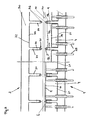
- the device 2 can be designed as shown in FIG. 2.
- the wall-like device 2 the after Assigned top surface of a glass pane 10 (above this arranged), a hollow chamber 30 and several on the glass pane 10 or the support device 1 to projecting ribs 31.
- a hollow chamber 30 In the Wall parts 32 of the hollow chamber 30 and in the side walls of the ribs 31 are openings 33 and 34 for the escape of hot air (at Transport) and cold air (when quenching).
- openings 33 and 34 for the escape of hot air (at Transport) and cold air (when quenching).
- the free edges 35 of the ribs 31 are strips 36 made of heat-resistant Material (e.g. Kevlar, brand name) used.
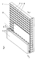
- Figs. 2 and 3 are in a preferred embodiment the support wall 1 according to the invention between the support wall 1 fixed, preferably hollow support ribs 3 hollow chambers 4 provided with movable wall parts 11.
- the moveable Wall parts 11 of the hollow chambers 4 are in the direction perpendicular to the plane the glass pane 10 is movable relative to the support ribs 3 in such a way that their distance from the conveyor plane of the glass sheet 10 by the the glass pane 10 facing free edges (narrow sides) 5 of the Support ribs 3 is defined, can be changed.
- Wall parts 11 of the hollow chambers 4 connected with rods 25 which in turn with drives (not shown) (e.g. pressure medium motors) are coupled.
- the supporting ribs 3 have narrow sides facing the glass pane 10 5, in which strips 6 made of heat-resistant plastic are used. In addition, 5 of the support ribs in the narrow sides 3 holes (slots) for the escape of air, in particular of hot air.
- the strips 36 made of heat-resistant Plastic does not have to cover the entire height of the narrow sides 5 of the support ribs 3 go through, but can be interrupted, the outlet openings for hot air in the area of the interruptions can be trained. Continuous are preferred Strips 36 and provided in the side walls of the support ribs 3, preferably slot-shaped outlet openings 20 for air. The Outlet openings 20 are released when the between support ribs 3 arranged, movable wall parts 11 of the hollow chambers 4th withdrawn (Fig. 3 right).
- the support ribs 3 are fixed in the machine frame and in aligned essentially vertical planes, being that of the glass sheet 10 facing narrow sides 5 of the support ribs 3 with a vertical plane, for example, a small angle (about 5 to 7 °) include so that one over an air cushion (air cushion) on the Support wall 1 by the support ribs 3 and the movable wall parts 11 of the hollow chambers 4 is formed, via the gas or air; upholstered ("L”) leaning glass pane 10 as for transporting Glass panes 10 usual, with the perpendicular an acute angle includes.
- the hollow chambers 4 are pressurized with air via openings 21, which exits through openings 9 in the wall parts 11 of the hollow chambers 4.
- wall parts 11 of the Hollow chambers 4 have these from the conveying plane of a glass sheet 10 a larger distance, e.g. a distance 20 to 25 mm larger, than the narrow sides 5 of the support ribs 3.
- a device for transporting and cooling hot glass panes 10 has a support wall 1, in the alternating fixed Support ribs 3 and between two support ribs 3 hollow chambers 4th with wall parts 11 which are perpendicular to the glass pane 10 are adjustable, are provided.
- the movable wall parts 11 When transporting a sheet of glass 10 are the movable wall parts 11 essentially with the free edges 5 of the support ribs 3 aligned.
- the hollow chambers 4 with hot air so acted that between the glass 10 and the support wall 1 when pushed onto the glass pane 10 Wall parts 11 forms a thin gas cushion "L" from hot air.
Landscapes
- Chemical & Material Sciences (AREA)
- Engineering & Computer Science (AREA)
- Materials Engineering (AREA)
- Organic Chemistry (AREA)
- Physics & Mathematics (AREA)
- Thermal Sciences (AREA)
- Re-Forming, After-Treatment, Cutting And Transporting Of Glass Products (AREA)
- Chain Conveyers (AREA)
Abstract
Description
Claims (16)
- Vorrichtung zum Transportieren und zum Abkühlen heißer Glasscheiben (10) mit zu beiden Seiten der Glasscheibe (10) angeordneten Wänden (1, 2), aus welchen beim Transportieren einer Glasscheibe (10) heiße Luft und beim Abkühlen einer Glasscheibe (10) kalte Luft oder ein anderes kaltes Gas auf die Glasscheibe (10) geleitet wird, dadurch gekennzeichnet, daß wenigstens eine der Wände als Stützwand (1) ausgebildet ist, in der abwechselnd Stützrippen (3) und zwischen jeweils zwei benachbarten Stützrippen (3) Wandteile (11) vorgesehen sind, daß die Stützrippen (3) weiter in Richtung auf die Glasscheibe (10) vorstehen als die zwischen den Stützrippen (3) vorgesehenen Wandteile (11), und daß wenigstens in den Wandteilen (11) Austrittsöffnungen (9) für heiße bzw. kalte Luft oder Gas vorgesehen sind.
- Vorrichtung nach Anspruch 1, dadurch gekennzeichnet, daß sowohl die Stützrippen (3), als auch die Wandteile (11) mit Austrittsöffnungen (9, 20) für heiße und kalte Luft oder Gas ausgebildet sind.
- Vorrichtung nach Anspruch 1 oder 2, dadurch gekennzeichnet, daß die Stützrippen (3) als hohle Rippen ausgebildet sind.
- Vorrichtung nach Anspruch 3, dadurch gekennzeichnet, daß in den zur Glasscheibe (10) annähernd senkrechten Seitenwänden der hohlen Stützrippen (3) Austrittsöffnungen (20) vorgesehen sind.
- Vorrichtung nach Anspruch 4, dadurch gekennzeichnet, daß die Austrittsöffnungen (20) der Stützrippen (3) als Langschlitze ausgebildet sind.
- Vorrichtung nach einem der Ansprüche 1 bis 5, dadurch gekennzeichnet, daß in den Schmalseiten (5) der Stützrippen (3) Leisten (36) aus elastischem, hitzebeständigem Werkstoff eingesetzt sind.
- Vorrichtung nach Anspruch 6, dadurch gekennzeichnet, daß die Leisten (36) aus elastischem Werkstoff über die Länge der Stützrippen (3) durchgehend ausgebildet sind.
- Vorrichtung nach einem der Ansprüche 1 bis 7, dadurch gekennzeichnet, daß die Stützrippen (3) in der Stützwand (1) ortsfest angeordnet sind und daß die zwischen den Stützrippen (3) angeordneten Wandteile (11) in Richtung senkrecht zur Ebene der Stützwand (1) verstellbar sind.
- Vorrichtung nach einem der Ansprüche 1 bis 8, dadurch gekennzeichnet, daß die zwischen den Stützrippen (3) vorgesehenen Wandteile (11) der Glasscheibe (10) zugekehrte Wände von Kammern (4) sind, die hohl ausgebildet sind.
- Vorrichtung nach Anspruch 9, dadurch gekennzeichnet, daß die der Glasscheibe (10) zugekehrten Wände der hohlen Kammern (4) die in Richtung senkrecht zur Ebene der Glasscheibe (10) verstellbaren Wandteile (11) sind.
- Vorrichtung nach einem der Ansprüche 8 bis 10, dadurch gekennzeichnet, daß beim Transportieren einer Glasscheibe (10) die beweglichen Wandteile (11) mit ihrer der Glasscheibe (10) zugekehrten Seite im wesentlichen mit den Schmalseiten (5) der Stützrippen (3) fluchtend ausgerichtet sind.
- Vorrichtung nach einem der Ansprüche 8 bis 11, dadurch gekennzeichnet, daß zum Abkühlen einer Glasscheibe (10) die beweglichen Wandteile (11) gegenüber den Schmalseiten (5) der Stützrippen (3) auf einen größeren Abstand von der Glasscheibe (10) zurückversetzt sind.
- Vorrichtung nach einem der Ansprüche 10 bis 12, dadurch gekennzeichnet, daß beim Transportieren einer Glasscheibe (10) die hohlen Kammern (4) mit heißer Luft derart beaufschlagt sind, daß zwischen der Glasscheibe (10) und der Stützwand (1) bei auf die Glasscheibe (10) zu vorgeschobenen Wandteilen (11) ein Gaspolster (L) aus heißer Luft ausgebildet wird.
- Vorrichtung nach einem der Ansprüche 8 bis 13, dadurch gekennzeichnet, daß zum Abkühlen einer Glasscheibe (10) die beweglichen Wandteile (11) gegenüber der Glasscheibe (10) zurückversetzt sind und aus den Stützrippen (3) kalte Luft ausgeblasen wird.
- Vorrichtung nach einem der Ansprüche 8 bis 14, dadurch gekennzeichnet, daß zum Abkühlen einer Glasscheibe (10) die beweglichen Wandteile (11) gegenüber der Glasscheibe (10) zurückversetzt sind und aus den hohlen Kammern (4) kalte Luft ausgeblasen wird.
- Vorrichtung nach einem der Ansprüche 8 bis 15, dadurch gekennzeichnet, daß die Stützrippen (13) in Vertikalebenen, die senkrecht zur Förderebene der Glasscheibe (10) ausgerichtet sind, angeordnet sind, wobei die Schmalseiten (5) der Stützrippen (3) mit der Lotrechten einen spitzen Winkel einschließen.
Applications Claiming Priority (2)
| Application Number | Priority Date | Filing Date | Title |
|---|---|---|---|
| AT32698 | 1998-02-24 | ||
| AT0032698A AT406046B (de) | 1998-02-24 | 1998-02-24 | Vorrichtung zum transportieren und kühlen von glasscheiben |
Publications (2)
| Publication Number | Publication Date |
|---|---|
| EP0937688A2 true EP0937688A2 (de) | 1999-08-25 |
| EP0937688A3 EP0937688A3 (de) | 1999-09-01 |
Family
ID=3487613
Family Applications (1)
| Application Number | Title | Priority Date | Filing Date |
|---|---|---|---|
| EP99890047A Withdrawn EP0937688A3 (de) | 1998-02-24 | 1999-02-09 | Vorrichtung zum Transportieren und Kühlen von Glasscheiben |
Country Status (4)
| Country | Link |
|---|---|
| US (1) | US6192711B1 (de) |
| EP (1) | EP0937688A3 (de) |
| AT (1) | AT406046B (de) |
| DE (1) | DE29902433U1 (de) |
Cited By (1)
| Publication number | Priority date | Publication date | Assignee | Title |
|---|---|---|---|---|
| WO2012142629A1 (de) * | 2011-04-18 | 2012-10-26 | Inova Lisec Technologiezentrum Gmbh | Verfahren und vorrichtung zum härten von glas |
Families Citing this family (10)
| Publication number | Priority date | Publication date | Assignee | Title |
|---|---|---|---|---|
| DE10045479A1 (de) | 2000-09-14 | 2002-04-04 | Schott Glas | Verfahren und Vorrichtung zum kontaktlosen Lagern und Transportieren von Flachglas |
| DE102004059727B4 (de) * | 2004-12-11 | 2012-07-26 | Schott Ag | Vorrichtung und Verfahren zum kontaktlosen Transportieren oder Lagern von Glas oder Glaskeramik |
| ES2396037T3 (es) * | 2008-06-19 | 2013-02-18 | Rena Gmbh | Procedimiento y dispositivo para transportar objetos |
| WO2012119034A2 (en) * | 2011-03-02 | 2012-09-07 | Game Changers, Llc | Method and apparatus for a dynamic air cushion transport system |
| FI126760B (fi) * | 2010-01-11 | 2017-05-15 | Glaston Services Ltd Oy | Menetelmä ja laite lasilevyjen kannattamiseksi ja kuumentamiseksi kuumalla kaasutyynyllä |
| JP5669001B2 (ja) * | 2010-07-22 | 2015-02-12 | 日本電気硝子株式会社 | ガラスフィルムの割断方法、ガラスロールの製造方法、及びガラスフィルムの割断装置 |
| US9951553B2 (en) | 2014-06-05 | 2018-04-24 | Erdman Automation Corporation | High speed parallel process insulated glass manufacturing line |
| US10253552B2 (en) | 2016-04-21 | 2019-04-09 | Erdman Automation Corporation | High speed parallel process insulated glass manufacturing line |
| CN111386235B (zh) * | 2017-10-31 | 2023-04-07 | 康宁公司 | 用于处理薄玻璃带的系统及方法 |
| US12467311B2 (en) | 2022-01-12 | 2025-11-11 | Erdman Automation Corporation | Insulated glass unit manufacturing station and assembly line with controlled heating of spacer |
Family Cites Families (9)
| Publication number | Priority date | Publication date | Assignee | Title |
|---|---|---|---|---|
| US3615315A (en) * | 1962-04-19 | 1971-10-26 | Ppg Industries Inc | Method and apparatus having sealing means and gaseous takeoff for float glass |
| US3337317A (en) * | 1962-07-02 | 1967-08-22 | Libbey Owens Ford Glass Co | Method and apparatus for producing a continuous glass ribbon |
| FR1527937A (fr) * | 1967-03-31 | 1968-06-07 | Saint Gobain | Dispositif de transport d'un matériau en forme de feuille sur un coussin gazeux |
| GB1275047A (en) * | 1968-06-14 | 1972-05-24 | Pilkington Brothers Ltd | Improvements in or relating to a process and apparatus for treating glass sheets |
| US3665730A (en) * | 1970-06-11 | 1972-05-30 | Frederick D Linzer | Apparatus for simultaneously supporting, cooling and shaping glass sheet and the like |
| JPS4843363B1 (de) * | 1970-07-16 | 1973-12-18 | ||
| US4046543A (en) * | 1976-04-23 | 1977-09-06 | Ppg Industries, Inc. | Method and apparatus for tempering moving glass sheets |
| US5281249A (en) * | 1993-06-01 | 1994-01-25 | Corning Incorporated | Reshaping a glass lens blank suspended on a flow of gas |
| US5669954A (en) * | 1994-06-20 | 1997-09-23 | Gas Research Institute | Forced convection heating apparatus and process for heating glass sheets therewithin |
-
1998
- 1998-02-24 AT AT0032698A patent/AT406046B/de not_active IP Right Cessation
-
1999
- 1999-02-09 EP EP99890047A patent/EP0937688A3/de not_active Withdrawn
- 1999-02-11 DE DE29902433U patent/DE29902433U1/de not_active Expired - Lifetime
- 1999-02-24 US US09/256,769 patent/US6192711B1/en not_active Expired - Fee Related
Cited By (2)
| Publication number | Priority date | Publication date | Assignee | Title |
|---|---|---|---|---|
| WO2012142629A1 (de) * | 2011-04-18 | 2012-10-26 | Inova Lisec Technologiezentrum Gmbh | Verfahren und vorrichtung zum härten von glas |
| US9221708B2 (en) | 2011-04-18 | 2015-12-29 | Lisec Austria Gmbh | Method and device for tempering glass |
Also Published As
| Publication number | Publication date |
|---|---|
| DE29902433U1 (de) | 1999-05-06 |
| US6192711B1 (en) | 2001-02-27 |
| AT406046B (de) | 2000-01-25 |
| ATA32698A (de) | 1999-06-15 |
| EP0937688A3 (de) | 1999-09-01 |
Similar Documents
| Publication | Publication Date | Title |
|---|---|---|
| DE68908614T2 (de) | Vorrichtung zur Herstellung von gebogenen Glasscheiben. | |
| AT412719B (de) | Verfahren und vorrichtung zum bereichsweisen entschichten von glasscheiben | |
| DE1421784B2 (de) | ||
| DE3101342A1 (de) | "verfahren zur herstellung von gasgefuellten isolierglaseinheiten und vorrichtung zur durchfuehrung des verfahrens" | |
| DE3101839A1 (de) | Vorrichtung und verfahren zum erhitzen und kuehlen von werkstuecken, insbesondere zum tempern von glas | |
| DE69833871T2 (de) | Vorrichtung zur härtung gebogenen glasscheiben | |
| DE69514480T2 (de) | Kontinuierlichen Ofen zum Heizen von Glasscheiben auf Biege- und/oder Härtungstemperatur | |
| DE3525909A1 (de) | Geraet und verfahren zum biegen von glasscheiben | |
| EP0937688A2 (de) | Vorrichtung zum Transportieren und Kühlen von Glasscheiben | |
| DE102004005703B4 (de) | Verfahren und Apparatur zur kontinuierlichen Formung eines Streifens aus Kunststoff mit einem gewellten Profil | |
| DE1778475B1 (de) | Einrichtung zum herstellen von formbehaeltern aus einer folie aus thermoplastischem kunststoff | |
| DE3632556C1 (de) | Verfahren und Vorrichtung zum Biegen einer Glasscheibe | |
| DE2242492B2 (de) | Kontinuierlich arbeitende presse | |
| DE2111104C3 (de) | Vorrichtung und Verfahren zum Biegen von Glasscheiben | |
| DE2441081C3 (de) | Anlage zum Vulkanisieren eines Fördergurtes | |
| DE2729263A1 (de) | Vorrichtung zum kontinuierlichen pressen von pressgutmatten im zuge der herstellung von spanplatten, faserplatten u.dgl. | |
| DE1471991B2 (de) | Blaskopfanordnung, insbesondere zum Kühlen von Glasscheiben | |
| DE2904943A1 (de) | Verfahren zum verdichten von offenzelligem polyurethan-schaumstoff | |
| EP0022136B1 (de) | Schrägwalzenrichtmaschine | |
| DE2055252A1 (de) | Verfahren zum Verformen von Glas scheiben und Vorrichtung zur Durchfuhrung des Verfahrens | |
| DE2350591C3 (de) | Vorrichtung zum Kühlen von erwärmten Glasscheiben für deren thermisches Vorspannen | |
| DE3788272T2 (de) | Verfahren und Vorrichtung zum Biegen und Tempern von Glasscheiben. | |
| DE1778475C (de) | Einrichtung zum Herstellen von Formbehältern aus einer Folie aus thermoplastischem Kunststoff | |
| DE636893C (de) | Verfahren und Vorrichtungen zum Haerten von Glastafeln | |
| DE2216940A1 (de) | Fördervorrichtung für Glasbänder |
Legal Events
| Date | Code | Title | Description |
|---|---|---|---|
| PUAI | Public reference made under article 153(3) epc to a published international application that has entered the european phase |
Free format text: ORIGINAL CODE: 0009012 |
|
| PUAL | Search report despatched |
Free format text: ORIGINAL CODE: 0009013 |
|
| AK | Designated contracting states |
Kind code of ref document: A2 Designated state(s): AT BE CH DE DK ES FI FR GB GR IE IT LI LU MC NL PT SE |
|
| AX | Request for extension of the european patent |
Free format text: AL;LT;LV;MK;RO;SI |
|
| AK | Designated contracting states |
Kind code of ref document: A3 Designated state(s): AT BE CH CY DE DK ES FI FR GB GR IE IT LI LU MC NL PT SE |
|
| AX | Request for extension of the european patent |
Free format text: AL;LT;LV;MK;RO;SI |
|
| 17P | Request for examination filed |
Effective date: 19990827 |
|
| AKX | Designation fees paid |
Free format text: AT BE CH DE DK ES FI FR GB GR IE IT LI LU MC NL PT SE |
|
| AXX | Extension fees paid |
Free format text: AL PAYMENT 19990827;LT PAYMENT 19990827;LV PAYMENT 19990827;MK PAYMENT 19990827;RO PAYMENT 19990827;SI PAYMENT 19990827 |
|
| 17Q | First examination report despatched |
Effective date: 20030205 |
|
| STAA | Information on the status of an ep patent application or granted ep patent |
Free format text: STATUS: THE APPLICATION IS DEEMED TO BE WITHDRAWN |
|
| 18D | Application deemed to be withdrawn |
Effective date: 20030617 |