EP0937674B1 - Dispositif enrouleur de tuyau - Google Patents
Dispositif enrouleur de tuyau Download PDFInfo
- Publication number
- EP0937674B1 EP0937674B1 EP98102566A EP98102566A EP0937674B1 EP 0937674 B1 EP0937674 B1 EP 0937674B1 EP 98102566 A EP98102566 A EP 98102566A EP 98102566 A EP98102566 A EP 98102566A EP 0937674 B1 EP0937674 B1 EP 0937674B1
- Authority
- EP
- European Patent Office
- Prior art keywords
- hose
- rolling system
- axle
- drum
- locking
- Prior art date
- Legal status (The legal status is an assumption and is not a legal conclusion. Google has not performed a legal analysis and makes no representation as to the accuracy of the status listed.)
- Expired - Lifetime
Links
Images


Classifications
-
- B—PERFORMING OPERATIONS; TRANSPORTING
- B65—CONVEYING; PACKING; STORING; HANDLING THIN OR FILAMENTARY MATERIAL
- B65H—HANDLING THIN OR FILAMENTARY MATERIAL, e.g. SHEETS, WEBS, CABLES
- B65H75/00—Storing webs, tapes, or filamentary material, e.g. on reels
- B65H75/02—Cores, formers, supports, or holders for coiled, wound, or folded material, e.g. reels, spindles, bobbins, cop tubes, cans, mandrels or chucks
- B65H75/34—Cores, formers, supports, or holders for coiled, wound, or folded material, e.g. reels, spindles, bobbins, cop tubes, cans, mandrels or chucks specially adapted or mounted for storing and repeatedly paying-out and re-storing lengths of material provided for particular purposes, e.g. anchored hoses, power cables
- B65H75/38—Cores, formers, supports, or holders for coiled, wound, or folded material, e.g. reels, spindles, bobbins, cop tubes, cans, mandrels or chucks specially adapted or mounted for storing and repeatedly paying-out and re-storing lengths of material provided for particular purposes, e.g. anchored hoses, power cables involving the use of a core or former internal to, and supporting, a stored package of material
- B65H75/44—Constructional details
- B65H75/4418—Arrangements for stopping winding or unwinding; Arrangements for releasing the stop means
- B65H75/4428—Arrangements for stopping winding or unwinding; Arrangements for releasing the stop means acting on the reel or on a reel blocking mechanism
- B65H75/4434—Arrangements for stopping winding or unwinding; Arrangements for releasing the stop means acting on the reel or on a reel blocking mechanism actuated by pulling on or imparting an inclination to the material
-
- B—PERFORMING OPERATIONS; TRANSPORTING
- B65—CONVEYING; PACKING; STORING; HANDLING THIN OR FILAMENTARY MATERIAL
- B65H—HANDLING THIN OR FILAMENTARY MATERIAL, e.g. SHEETS, WEBS, CABLES
- B65H75/00—Storing webs, tapes, or filamentary material, e.g. on reels
- B65H75/02—Cores, formers, supports, or holders for coiled, wound, or folded material, e.g. reels, spindles, bobbins, cop tubes, cans, mandrels or chucks
- B65H75/34—Cores, formers, supports, or holders for coiled, wound, or folded material, e.g. reels, spindles, bobbins, cop tubes, cans, mandrels or chucks specially adapted or mounted for storing and repeatedly paying-out and re-storing lengths of material provided for particular purposes, e.g. anchored hoses, power cables
- B65H75/38—Cores, formers, supports, or holders for coiled, wound, or folded material, e.g. reels, spindles, bobbins, cop tubes, cans, mandrels or chucks specially adapted or mounted for storing and repeatedly paying-out and re-storing lengths of material provided for particular purposes, e.g. anchored hoses, power cables involving the use of a core or former internal to, and supporting, a stored package of material
- B65H75/44—Constructional details
- B65H75/4478—Constructional details relating to handling of fluids
-
- B—PERFORMING OPERATIONS; TRANSPORTING
- B65—CONVEYING; PACKING; STORING; HANDLING THIN OR FILAMENTARY MATERIAL
- B65H—HANDLING THIN OR FILAMENTARY MATERIAL, e.g. SHEETS, WEBS, CABLES
- B65H2701/00—Handled material; Storage means
- B65H2701/30—Handled filamentary material
- B65H2701/33—Hollow or hose-like material
-
- Y—GENERAL TAGGING OF NEW TECHNOLOGICAL DEVELOPMENTS; GENERAL TAGGING OF CROSS-SECTIONAL TECHNOLOGIES SPANNING OVER SEVERAL SECTIONS OF THE IPC; TECHNICAL SUBJECTS COVERED BY FORMER USPC CROSS-REFERENCE ART COLLECTIONS [XRACs] AND DIGESTS
- Y10—TECHNICAL SUBJECTS COVERED BY FORMER USPC
- Y10T—TECHNICAL SUBJECTS COVERED BY FORMER US CLASSIFICATION
- Y10T137/00—Fluid handling
- Y10T137/6851—With casing, support, protector or static constructional installations
- Y10T137/6918—With hose storage or retrieval means
- Y10T137/6925—With flow regulation responsive to hose movement
- Y10T137/6929—Reel type
-
- Y—GENERAL TAGGING OF NEW TECHNOLOGICAL DEVELOPMENTS; GENERAL TAGGING OF CROSS-SECTIONAL TECHNOLOGIES SPANNING OVER SEVERAL SECTIONS OF THE IPC; TECHNICAL SUBJECTS COVERED BY FORMER USPC CROSS-REFERENCE ART COLLECTIONS [XRACs] AND DIGESTS
- Y10—TECHNICAL SUBJECTS COVERED BY FORMER USPC
- Y10T—TECHNICAL SUBJECTS COVERED BY FORMER US CLASSIFICATION
- Y10T137/00—Fluid handling
- Y10T137/6851—With casing, support, protector or static constructional installations
- Y10T137/6918—With hose storage or retrieval means
- Y10T137/6932—With retrieval means
- Y10T137/6943—Biased to retracted position
-
- Y—GENERAL TAGGING OF NEW TECHNOLOGICAL DEVELOPMENTS; GENERAL TAGGING OF CROSS-SECTIONAL TECHNOLOGIES SPANNING OVER SEVERAL SECTIONS OF THE IPC; TECHNICAL SUBJECTS COVERED BY FORMER USPC CROSS-REFERENCE ART COLLECTIONS [XRACs] AND DIGESTS
- Y10—TECHNICAL SUBJECTS COVERED BY FORMER USPC
- Y10T—TECHNICAL SUBJECTS COVERED BY FORMER US CLASSIFICATION
- Y10T137/00—Fluid handling
- Y10T137/6851—With casing, support, protector or static constructional installations
- Y10T137/6918—With hose storage or retrieval means
- Y10T137/6954—Reel with support therefor
-
- Y—GENERAL TAGGING OF NEW TECHNOLOGICAL DEVELOPMENTS; GENERAL TAGGING OF CROSS-SECTIONAL TECHNOLOGIES SPANNING OVER SEVERAL SECTIONS OF THE IPC; TECHNICAL SUBJECTS COVERED BY FORMER USPC CROSS-REFERENCE ART COLLECTIONS [XRACs] AND DIGESTS
- Y10—TECHNICAL SUBJECTS COVERED BY FORMER USPC
- Y10T—TECHNICAL SUBJECTS COVERED BY FORMER US CLASSIFICATION
- Y10T137/00—Fluid handling
- Y10T137/8593—Systems
- Y10T137/86268—With running joint between movable parts of system
Definitions
- the present invention relates to a hose reel system according to the preamble of claim 1.
- the present invention relates to a Hose reel system for a hose, in particular for the hose of a hand shower.
- hand showers are used in a wide variety of areas. Areas of application are in kitchen appliances, such as damper devices, Hot air steamers and hot air devices, generally for cleaning processes inside and outside the Sanitary area, in laboratories etc.
- hand shower devices are used to do this serve a gaseous or liquid medium in such Install or insert devices. This is preferred with a hand shower used by the operator, which is connected to a hose that holds the medium feeds the hand shower.
- the operator operates the hand shower and sprays for example the kitchen appliance in all its corners and Angles out to clean it completely. Or it will for example, additional liquid in the cooking chamber, for example to quench the cooking products after the cooking process injected. To the respective cleaning points or other places, it is necessary that the hand shower attached to a hose in all areas of the kitchen appliance can be moved, which is a corresponding Length of hose required.
- hose save space is housed, and also after the cleaning process can be stowed away to save space.
- Hose reel systems are known in the prior art.
- a hose reel system is known from US-A-1,675,140, which has a hose reel on which the Hose is wound accordingly. Via a feed line the liquid is introduced axially into an axis and wound radially out of this axis into the Hose forwarded.
- a locking device Connected to the hose reel is a locking device that uses the hose reel two cam elements each provided with a nose can be locked in two places.
- a spring device on the hose reel in the unwinding direction of the hose and after releasing the locking device drives in the winding direction.
- EP-A-493 736 is also a hose reel system known, provided in the circumferential locking devices are the corresponding locking states in engagement with cams let generate.
- the hose reel will also with the help of a spring device, in particular in Form of a spiral spring in the winding direction of the hose is acted upon and by releasing the locking device allows the hose to be wound up.
- Another hose reeling system is known from EP-A-667 312, the one has rotatable hose reel, which around a sleeve-shaped, in the direction of Axis of rotation of the drum arranged feed device for the medium is.
- An additional sleeve is provided between the drum and the feed device, which is held in place by friction by means of a clamping device is, but also with sufficient force around the axis of rotation of the drum is rotatable.
- an opening is provided, which is approximately the diameter of the hose.
- the present invention has for its object a hose reel system to create for a hose with a hose winder in which only in certain operating states of the hose winding device Medium can be output and in the idle state the supply of the medium is automatically locked, the winding and unwinding of the hose and the setting of the operating state suitable for dispensing the medium for the operator as simple and easy as possible in combination with a locking device the hose reel and at the same time the largest possible Medium flow should be guaranteed.
- the invention is distinguished Hose reel system characterized in that the axis is a circular segment Incision or a circular segment-shaped notch, the or in Connection is with an axial channel in the axis that the axis circumferential grooves on both sides of the notch and two extending in the axial direction of the axis Has grooves in the vicinity of the notch, which is used to receive a sealing device serve, and that the sealing device, the medium flow only over a certain
- the circumferential area of the axis allows the locking device to interact in such a way that the medium flow only takes place in the area of the locking device through the locking device, with essentially the full medium flow in the defined peripheral region is present.
- the hose reel system according to the invention is particularly simple and compact design and can therefore save space and accordingly be realized inexpensively.
- the axis has circumferential grooves for effective positioning of the sealing device on both sides of the incision or notch.
- the sealing device of the Hose reel system according to the invention on two concentric rings with two Crosspieces are connected.
- the connecting webs are symmetrical to the center or to Central axis of the concentric rings arranged.
- the cross section of the rings of the sealing device is advantageous essentially circular, which leads to a particularly effective sealing effect.
- the axis points in the area of your one end on the outer circumference a flattening out. This allows the position of the axis are determined and thus a shut-off of the medium To be defined.
- the flattening advantageously shows the position of the incision or the axial outlet opening of the medium feed device.
- the locking device of the hose reel system according to the invention is preferably made from a ring gear section and a locking cam formed with the ring gear section can be brought into engagement and released again from this is.
- the ring gear is essentially semicircular trained so that locking the Hose reel over their half circumference is made possible.
- the ring gear is integrally formed on the hose drum.
- connection device that is used for the connection of the rewound Hose is used according to the invention as one rotatable sleeve formed on the axis, which has a corresponding Has hose connection element.
- the connecting device integrally formed on the hose drum.
- a socket is also provided to the the connecting device extends and extends with it rotates together around the axis.
- the connecting device has a connecting element to connect to the hose reel.
- This can advantageously be in the form of a substantially circular or flattened plate. This is then, for example, by means of screws or other Fasteners connected to the hose reel.
- a particularly compact design of the invention Hose reel system is achieved in that the Hose drum continues the outer linkage of the spring device having.
- the spiral-shaped spring device is advantageous at its inner articulation area on the axis of the Hose winding device articulated. This results in simple and space-saving training of the individual Elements of the hose reel system.
- This space-saving Construction is advantageously increased in that the spring device is arranged within the hose drum is.
- the inner articulation device is advantageously the Axle is cam-shaped and also has several cams on.
- the cam or cams is particularly advantageous in the counter-pressure direction the spring device beveled so that a Sliding the inner end of the spring unit over a cam to the next in the event of an overload corresponding to an overextension against the intended clamping direction becomes.
- This is advantageous in the case of spiral springs frequently occurring disadvantage avoided that over-tightening the coil spring in the other direction, which in such Hose winding systems is possible, is avoided, and hence the coil spring normally occurring is avoided.
- Figure 1 is a hose reel system according to the invention in section 1 shown. This has a hose reel 3 on, with a winding body 5 and a radial running side wall 7. The hose reel rotates about its axis of rotation 4.
- the hose reel 3 has a hub section 8 with a through opening 9 through which an axis 11 extends.
- the axis is referenced are described in more detail in FIG.
- This feed device 13 has an inlet opening 15 and an outlet opening 17.
- a connecting device 19 is arranged around the axis 11, which on the one hand serves to wind up the Hose (not shown) with the feed device 13 to connect and on the other hand for connection with the Hose reel 3 to ensure contactless around the axis 11 is arranged.
- the hose reel system according to the invention a gear rim section designed as a latching device 21, which is connected to the side wall 7.
- the ring gear section 21 is in engagement with a locking cam 23, which is shown in more detail in FIGS. 7 and 8.
- the Locking cam 23 is pivotally attached to a housing wall 25.
- the outer portion of the end portion of the axis 11 that the Has inlet opening 15, has a thread 27, the serves to accommodate a mother.
- To secure the position of the A spacer ring 31 is provided on the housing against which the mother can be determined.
- the hose reel 3 has at its opposite end an axial cover 33, which the lateral support of the Hose serves.
- the hose becomes an connection device through an opening 35 19 out.
- the hose drum 3 is shown in a sectional view. As can be seen at the opening 35 opposite Section of the side wall 7 of the ring gear section 21 arranged.
- the ring gear section extends 21 substantially semicircular, i.e. H. along half the circumference of the hose reel.
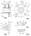
- FIG 4 is the sectional view of the connecting device 19 shown. This has a sleeve 37 and has one Connection element 39 for the hose.
- the connector 39 is designed in the form of a pipe socket and has blind hole 41 on.
- a passage opening 43 is provided a connection between the medium supply and the hose or the hand shower attached to it (not shown) should create.
- the connecting device has 19 a plate-shaped connecting element 45, which is approximately circular.
- Figure 6 shows the view along the line VI-VI of Figure 4th
- FIG. 7 shows a side view of the locking cam 23. This is rotatably mounted on an axis 49 and has a cam-shaped end section 51.
- Figure 8 shows a sectional view along the line VIII-VIII of Figure 7.
- the cam-shaped end portion 51 is used for Engagement in locking notches 53 of the ring gear section 21 (FIG 1 to 3). The interaction is as follows.
- the locking lever 23 meets the locking notches 53, leads one Swivel movement and initially snaps into the first notch on. With further rotation of the hose drum 3 takes place snapping into the subsequent notches, whereby a clear chattering noise is generated. at each snap option will turn back Hose reel 3 prevented in the winding direction.
- an incision or a notch 57 is provided, the or the circular section is formed, as is clearly shown in Figure 12 and Figure 13.
- the incision or notch extends into the area of the blind hole 55, so that here a connection or a Passage for the medium is created.
- circumferential grooves 61 and 63 are provided, with between the circumferential grooves 61 and 63 only thin webs 65 and 67 arranged on the edge of the incision 57 are.
- auxiliary grooves 69 provided for Can accommodate additional sealing rings.
- the axis 11 also has a stop rib 71, and has a shoulder 73 which stops against the housing wall 25 ( Figure 1) is used.
- Axial grooves 75 and 76 are provided, which are also for receiving to serve as a seal.
- Figure 14 shows the view according to arrow Y of Figure 9. Zur Determining the position of the incision 57 is at an end region the axis 11 a flattening 77 is provided which the Indicates the location of the incision 57. Beyond that, however also the flat 77 with a corresponding counter surface cooperate in the spacer ring 31 ( Figure 1), so that at correct pre-assembly of the spacer ring 31 always the correct one Location of the incision related to the housing and of the locking cam 23 attached there.
- FIG. 15 A partial assembly of axis 11 is already shown in FIG shown with connecting device 19.
- Figure 16 is the view along line XVI-XVI of Figure 15 and the figure 17 is the view along line XVII-XVII of FIG. 15. How 15 and 17 can be seen, the sleeve 37 strikes the stop rib 71.
- FIGS. 18 to 20 the sealing device 59 of the Hose reel system according to the invention in a significantly enlarged Scale shown.
- the sealing device 59 has two equally large sealing rings 79 and 80, which have a substantially circular cross-section.
- Two connecting webs 81 connect the two rings 79 and 80. They are essentially in one plane, the cutting plane XX-XX of Figure 18.
- the seal can be made of a conventional material, such as for example, rubber, silicone or the like his.
- the connecting sections 81 come after assembly of the sealing device 59 to lie in the grooves 75 and 76 of the axis 11. If this is the case, then the connecting sections lock 81 on the circumferential side the upper area from the lower area as can be seen from FIG. In operation can be in any position in the passage opening 43 in the upper part of the axis 11, that is in the area of Incision 57 is made, a medium passage.
- the gear rim section 21 is located in the area of the locking cam 23, so that a substantially semi-circular area in each locking position a medium transport can be done in the hose.
- Figure 21 is a view of the installation space of a spring device 89 shown. This is inside the winding body 5 arranged and thus increases the space-saving and compact design of the hose reel system according to the invention.
- the outer end of a coil spring 90 (only shown in this area) in a linkage 83 hinged.
- Figure 22 shows the inner linkage 91 of a conventional used coil spring 90, which acts as a spring device 89 serves.
- the articulation device 91 is cam-like constructed and has a plurality of cams 93.
- the cams 93 in the pressure direction of the coil spring (in example case shown clockwise) slightly beveled. This allows the articulation end 95 of the spiral spring 90 Jump on to the next or next cam 93, if the spring is tensioned in the opposite direction, thereby avoiding spring breakage.
- the articulation device 91 is in the example case hexagonal shaft end 12 (see also figure 1) put on and arranged by the hexagonal profile.
Landscapes
- Storing, Repeated Paying-Out, And Re-Storing Of Elongated Articles (AREA)
- Quick-Acting Or Multi-Walled Pipe Joints (AREA)
Claims (18)
- Système d'enroulement pour un tuyau souple, notamment dispositif manuel de projection, au moyen duquel des fluides gazeux ou liquides peuvent être projetés, comprenant :caractériséun dispositif d'enroulement de tuyau souple (1), qui comprend un tambour de tuyau souple (3) qui est monté sur un axe (11),un dispositif d'introduction de fluide (13), qui est disposé au moins en partie dans l'axe (11) et comporte une ouverture d'entrée (15) et une ouverture de sortie (17),un dispositif de liaison (19), qui sert à relier le dispositif d'introduction de fluide (13) au tuyau souple,un dispositif d'arrêt en position (21, 23), qui sert à l'arrêt en position du tambour de tuyau souple (3) dans des zones périphériques déterminées de celui-ci,et un dispositif de ressort (90), qui sollicite le tambour de tuyau souple (3) dans le sens d'enroulement du tuyau souple et, une fois le dispositif d'arrêt en position libéré, entraíne le tambour de tuyau souple (3) dans le sens d'enroulement,en ce que l'axe (11) comporte une incision en forme de segment circulaire, ou une entaille en forme de segment circulaire (57), qui communique avec un conduit axial (55) situé dans l'axe (11),en ce que l'axe (11) comporte des gorges circonférentielles (61, 63) des deux côtés de l'entaille et deux rainures (75, 76) s'étendant suivant la direction axiale de l'axe (11) et situées au voisinage de l'entaille (57), qui servent à recevoir un dispositif d'étanchéité (59), eten ce que le dispositif d'étanchéité (59) n'autorise l'écoulement de fluide que par une zone circonférentielle déterminée de l'axe (11) et coopère avec le dispositif d'arrêt en position (21, 23) d'une manière telle que l'écoulement de fluide n'a lieu que dans la zone de l'arrêt en position au moyen du dispositif d'arrêt en position (21, 23), essentiellement la totalité de l'écoulement de fluide étant présente dans la zone périphérique déterminée.
- Système d'enroulement de tuyau souple suivant la revendication 1, caractérisé en ce que le dispositif d'étanchéité (59) est constitué de deux anneaux (79, 80) essentiellement de même grandeur et comprend deux segments de liaison (81) servant à relier les deux anneaux (79, 80).
- Système d'enroulement de tuyau souple suivant la revendication 2, caractérisé en ce que les segments de liaison (81) sont disposés d'une manière symétrique vis-à-vis de l'axe central des deux anneaux (79, 80).
- Système d'enroulement de tuyau souple suivant la revendication 2 ou 3, caractérisé en ce que la section transversale des anneaux (79, 80) du dispositif d'étanchéité (59) est essentiellement de forme circulaire.
- Système d'enroulement de tuyau souple suivant l'une des revendications 1 à 4, caractérisé en ce que, dans la zone de l'une de ses extrémités, l'axe (11) comporte un méplat (77) sur la périphérie extérieure.
- Système d'enroulement de tuyau souple suivant la revendication 5, caractérisé en ce que le méplat (77) correspond à la position de l'incision (57) ou de l'ouverture de sortie axiale du dispositif d'introduction de fluide (13).
- Système d'enroulement de tuyau souple suivant l'une des revendications 1 à 6, caractérisé en ce que le dispositif d'arrêt en position comprend un segment de couronne dentée (21) et une came d'arrêt (23).
- Système d'enroulement de tuyau souple suivant la revendication 7, caractérisé en ce que le segment de couronne dentée (21) est réalisé essentiellement avec une forme semi-circulaire.
- Système d'enroulement de tuyau souple suivant la revendication 7 ou 8, caractérisé en ce que le segment de couronne dentée (21) est réalisé d'une pièce, au formage, sur le tambour de tuyau souple (3).
- Système d'enroulement de tuyau souple suivant l'une des revendications 1 à 9, caractérisé en ce que le dispositif de liaison (19) comprend un manchon (37) qui peut tourner sur l'axe (11) et qui comporte un élément de raccordement de tuyau souple (39).
- Système d'enroulement de tuyau souple suivant l'une des revendications 1 à 9, caractérisé en ce que le dispositif de liaison (19) est un corps en forme de manchon qui est réalisé d'une pièce, au formage, sur le tambour de tuyau souple (3) et est disposé autour d'une douille rotative au moyen de laquelle il tourne autour de l'axe (11).
- Système d'enroulement de tuyau souple suivant l'une des revendications 1 à 11, caractérisé en ce que le dispositif de liaison (19) comprend un élément de liaison (45) servant à la liaison avec le tambour de tuyau souple (3).
- Système d'enroulement de tuyau souple suivant la revendication 12, caractérisé en ce que l'élément de liaison (45) est réalisé essentiellement sous forme d'une plaque circulaire ou présentant un pan coupé.
- Système d'enroulement de tuyau souple suivant l'une des revendications 1 à 13, caractérisé en ce que le tambour de tuyau souple (3) comprend en outre l'articulation extérieure du dispositif de ressort (90), de préférence dans le corps d'enroulement (5).
- Système d'enroulement de tuyau souple suivant l'une des revendications 1 à 14, caractérisé en ce que le dispositif de ressort (90) est disposé à l'intérieur du corps d'enroulement (5).
- Système d'enroulement de tuyau souple suivant l'une des revendications 1 à 15, caractérisé en ce que le dispositif de ressort (90), réalisé en forme de spirale, est articulé, dans sa zone d'articulation intérieure, sur l'axe (11) du dispositif d'enroulement de tuyau souple (3).
- Système d'enroulement de tuyau souple suivant la revendication 16, caractérisé en ce que le dispositif d'articulation intérieure (91) de l'axe (11) est réalisé en forme de came et comporte plusieurs cames (93).
- Système d'enroulement de tuyau souple suivant la revendication 17, caractérisé en ce que les cames (93) sont à flanc légèrement incliné dans le sens opposé au sens de pression du ressort (19), ce qui rend possible un glissement de l'extrémité intérieure (95) du dispositif de ressort (89) sur une came (93) au moins jusqu'à la suivante.
Priority Applications (3)
| Application Number | Priority Date | Filing Date | Title |
|---|---|---|---|
| DE59803505T DE59803505D1 (de) | 1998-02-13 | 1998-02-13 | Schlauchaufrollsystem |
| EP98102566A EP0937674B1 (fr) | 1998-02-13 | 1998-02-13 | Dispositif enrouleur de tuyau |
| US09/251,072 US6105605A (en) | 1998-02-13 | 1999-02-16 | System for rolling up hoses |
Applications Claiming Priority (1)
| Application Number | Priority Date | Filing Date | Title |
|---|---|---|---|
| EP98102566A EP0937674B1 (fr) | 1998-02-13 | 1998-02-13 | Dispositif enrouleur de tuyau |
Publications (2)
| Publication Number | Publication Date |
|---|---|
| EP0937674A1 EP0937674A1 (fr) | 1999-08-25 |
| EP0937674B1 true EP0937674B1 (fr) | 2002-03-27 |
Family
ID=8231413
Family Applications (1)
| Application Number | Title | Priority Date | Filing Date |
|---|---|---|---|
| EP98102566A Expired - Lifetime EP0937674B1 (fr) | 1998-02-13 | 1998-02-13 | Dispositif enrouleur de tuyau |
Country Status (3)
| Country | Link |
|---|---|
| US (1) | US6105605A (fr) |
| EP (1) | EP0937674B1 (fr) |
| DE (1) | DE59803505D1 (fr) |
Cited By (3)
| Publication number | Priority date | Publication date | Assignee | Title |
|---|---|---|---|---|
| DE102010026118A1 (de) | 2010-07-05 | 2012-01-05 | Mkn Maschinenfabrik Kurt Neubauer Gmbh & Co. | Schlauchaufrollsystem und damit ausgerüstetes Gargerät |
| DE102011105716A1 (de) | 2011-06-23 | 2012-12-27 | MKN Maschinenfabrik Kurt Neubauer GmbH & Co. KG | Gargerät mit einem Tiegel und Verfahren zur Reinigung des Tiegels |
| DE102015107755B4 (de) | 2015-04-17 | 2023-05-25 | Rational Aktiengesellschaft | Schlauchaufrollsystem |
Families Citing this family (5)
| Publication number | Priority date | Publication date | Assignee | Title |
|---|---|---|---|---|
| SE515396C2 (sv) * | 1999-05-12 | 2001-07-30 | Abb Ab | En svivel för flexibel transport av en fluid |
| US6766821B1 (en) * | 2003-02-24 | 2004-07-27 | Alert Stamping & Mfg. Co, Inc | Air hose reel |
| US20070098516A1 (en) * | 2005-11-02 | 2007-05-03 | Loftis Dwight D | Load-securing device usable with a load-transport system and related methods |
| DE102008031170B4 (de) * | 2008-07-03 | 2010-06-17 | Sartorius Stedim Biotech Gmbh | Adapter zur Befestigung eines Filterelementes |
| CN109125988B (zh) * | 2018-08-21 | 2020-09-18 | 浙江蓝特新能源科技股份有限公司 | 一种基于水射流的道路车辆救援装置 |
Family Cites Families (18)
| Publication number | Priority date | Publication date | Assignee | Title |
|---|---|---|---|---|
| US1675140A (en) * | 1926-05-20 | 1928-06-26 | Otto G Schenderlein | Automatic hose reel |
| CH200235A (de) * | 1936-09-04 | 1938-09-30 | Junkers & Co | Halteeinrichtung für Schlauchbrausen. |
| US3437105A (en) * | 1966-01-10 | 1969-04-08 | Chemetron Corp | Reel assembly |
| US3457946A (en) * | 1967-02-27 | 1969-07-29 | Raiford P Dean Jr | Hose reel in container |
| FR2082116A5 (fr) * | 1970-03-04 | 1971-12-10 | App Auxil Manutent | |
| SE353242B (fr) * | 1972-04-18 | 1973-01-29 | B Nederman | |
| US3865386A (en) * | 1973-04-20 | 1975-02-11 | Koehring Co | Oil sealing device |
| DE2850647A1 (de) * | 1978-11-22 | 1980-06-04 | Helmut Von Ameln | Schlauchbrausearmatur |
| US4446884A (en) * | 1981-06-08 | 1984-05-08 | Rader Jr Homer J | Take-up reel with controlled rewind velocity |
| US4487218A (en) * | 1982-06-25 | 1984-12-11 | Cascade Corporation | Line take-up assembly for a lift truck |
| NL8502159A (nl) * | 1985-07-30 | 1987-02-16 | Pieter Van T Veer | Slanghaspel. |
| DE3901007A1 (de) * | 1988-01-15 | 1989-07-27 | Grohe Kg Hans | Sanitaerarmatur |
| DE3812399A1 (de) * | 1988-04-14 | 1989-10-26 | Josef Lopatta | Vorrichtung zum aufwickeln von brauseschlaeuchen |
| DE9005113U1 (fr) * | 1989-05-08 | 1991-01-31 | Houben, Norbert, 4060 Viersen, De | |
| SE468894B (sv) * | 1990-12-19 | 1993-04-05 | Nederman Philip & Co Ab | Slang- eller kabelupprullare med fjaederupprullare |
| NL9400203A (nl) * | 1994-02-09 | 1995-09-01 | Jansen Frank P | Slanghaspel. |
| DE19505926A1 (de) * | 1995-02-21 | 1996-08-22 | Holzschuh Gmbh & Co Kg | Kabeltrommel |
| US5787923A (en) * | 1996-12-16 | 1998-08-04 | Mcneil (Ohio) Corporation | Hose reel assembly |
-
1998
- 1998-02-13 EP EP98102566A patent/EP0937674B1/fr not_active Expired - Lifetime
- 1998-02-13 DE DE59803505T patent/DE59803505D1/de not_active Expired - Lifetime
-
1999
- 1999-02-16 US US09/251,072 patent/US6105605A/en not_active Expired - Lifetime
Cited By (5)
| Publication number | Priority date | Publication date | Assignee | Title |
|---|---|---|---|---|
| DE102010026118A1 (de) | 2010-07-05 | 2012-01-05 | Mkn Maschinenfabrik Kurt Neubauer Gmbh & Co. | Schlauchaufrollsystem und damit ausgerüstetes Gargerät |
| EP2404858A2 (fr) | 2010-07-05 | 2012-01-11 | MKN Maschinenfabrik Kurt Neubauer GmbH & Co. | Système d'enroulement de tuyau et appareil de cuisson en étant équipé |
| DE102011105716A1 (de) | 2011-06-23 | 2012-12-27 | MKN Maschinenfabrik Kurt Neubauer GmbH & Co. KG | Gargerät mit einem Tiegel und Verfahren zur Reinigung des Tiegels |
| WO2012175564A1 (fr) | 2011-06-23 | 2012-12-27 | Mkn Maschinenfabrik Kurt Neubauer Gmbh & Co. | Appareil de cuisson pourvu d'une cuve et procédé pour nettoyer la cuve |
| DE102015107755B4 (de) | 2015-04-17 | 2023-05-25 | Rational Aktiengesellschaft | Schlauchaufrollsystem |
Also Published As
| Publication number | Publication date |
|---|---|
| EP0937674A1 (fr) | 1999-08-25 |
| US6105605A (en) | 2000-08-22 |
| DE59803505D1 (de) | 2002-05-02 |
Similar Documents
| Publication | Publication Date | Title |
|---|---|---|
| DE69838710T2 (de) | Einziehbare trommel mit kanälen versehenem sperrklinkenmechanismus | |
| DE102008052277B3 (de) | Spenderventilanordnung für ein Gefäß | |
| EP1200332B1 (fr) | Appareil manuel pour faire passer un film d'une bande support a un substrat | |
| DE102006052969B4 (de) | Anschlageinrichtung für die Öffen- und Schließbewegung einer Verschattungsanlage sowie Verschattungsanlage mit einer solchen Anschlageinrichtung | |
| DE112012003763B4 (de) | Restdruckentlastungsventil | |
| DE19621432A1 (de) | Baugruppe zur Verbindung eines Betätigungsorgans mit einem Drehabsperrorgan | |
| EP0271782B1 (fr) | Etau à ressort | |
| EP1882798B1 (fr) | Ferrure pour porte ou fenêtre | |
| EP0937674B1 (fr) | Dispositif enrouleur de tuyau | |
| EP0346377A1 (fr) | Support de stores. | |
| EP0475017B1 (fr) | Dispositif de réglage pour commande par câble | |
| EP1990304B1 (fr) | Palier pour un rouleau de corde | |
| DE10350698A1 (de) | Kupplungsmechanismus | |
| DE19913022B4 (de) | Korbspule für Draht, insbesondere für Schweißdraht | |
| EP1609637A1 (fr) | Tuyau de raccord pour un système de ventilation d'un véhicule | |
| EP0863103B1 (fr) | Dévidoire portatif de tuyau ou câble | |
| DE102010055681B4 (de) | Vorrichtung zum Haltern eines Gegenstands mit Gewichtsausgleich | |
| EP2404858B1 (fr) | Système d'enroulement de tuyau et appareil de cuisson en étant équipé | |
| DE2944801A1 (de) | Federbetaetigter aufwickelmechanismus | |
| EP0730911B1 (fr) | Douche à main | |
| DE102006047702A1 (de) | Türbeschlag | |
| EP0160892B1 (fr) | Capsule de ressort | |
| EP3297890B1 (fr) | Dispositifs de blocage | |
| DE102013012064B3 (de) | Spuleneinrichtung für Draht-Wickelgut, insbesondere für Schweißdraht-Wickelgut | |
| DE102010025062A1 (de) | Fensterabdeckung, die eine Wickelfunktion besitzt |
Legal Events
| Date | Code | Title | Description |
|---|---|---|---|
| PUAI | Public reference made under article 153(3) epc to a published international application that has entered the european phase |
Free format text: ORIGINAL CODE: 0009012 |
|
| 17P | Request for examination filed |
Effective date: 19981110 |
|
| AK | Designated contracting states |
Kind code of ref document: A1 Designated state(s): CH DE IT LI |
|
| AX | Request for extension of the european patent |
Free format text: AL;LT;LV;MK;RO;SI |
|
| AKX | Designation fees paid |
Free format text: CH DE IT LI |
|
| GRAG | Despatch of communication of intention to grant |
Free format text: ORIGINAL CODE: EPIDOS AGRA |
|
| GRAG | Despatch of communication of intention to grant |
Free format text: ORIGINAL CODE: EPIDOS AGRA |
|
| GRAH | Despatch of communication of intention to grant a patent |
Free format text: ORIGINAL CODE: EPIDOS IGRA |
|
| GRAH | Despatch of communication of intention to grant a patent |
Free format text: ORIGINAL CODE: EPIDOS IGRA |
|
| GRAA | (expected) grant |
Free format text: ORIGINAL CODE: 0009210 |
|
| AK | Designated contracting states |
Kind code of ref document: B1 Designated state(s): CH DE IT LI |
|
| REG | Reference to a national code |
Ref country code: CH Ref legal event code: EP |
|
| REF | Corresponds to: |
Ref document number: 59803505 Country of ref document: DE Date of ref document: 20020502 |
|
| PLBE | No opposition filed within time limit |
Free format text: ORIGINAL CODE: 0009261 |
|
| STAA | Information on the status of an ep patent application or granted ep patent |
Free format text: STATUS: NO OPPOSITION FILED WITHIN TIME LIMIT |
|
| 26N | No opposition filed |
Effective date: 20021230 |
|
| PGFP | Annual fee paid to national office [announced via postgrant information from national office to epo] |
Ref country code: CH Payment date: 20120227 Year of fee payment: 15 |
|
| PGFP | Annual fee paid to national office [announced via postgrant information from national office to epo] |
Ref country code: DE Payment date: 20120228 Year of fee payment: 15 |
|
| PGFP | Annual fee paid to national office [announced via postgrant information from national office to epo] |
Ref country code: IT Payment date: 20120222 Year of fee payment: 15 |
|
| REG | Reference to a national code |
Ref country code: DE Ref legal event code: R082 Ref document number: 59803505 Country of ref document: DE Representative=s name: VON LIERES BRACHMANN SCHULZE PATENTANWAELTE, DE Ref country code: DE Ref legal event code: R082 Ref document number: 59803505 Country of ref document: DE |
|
| REG | Reference to a national code |
Ref country code: CH Ref legal event code: PL |
|
| PG25 | Lapsed in a contracting state [announced via postgrant information from national office to epo] |
Ref country code: CH Free format text: LAPSE BECAUSE OF NON-PAYMENT OF DUE FEES Effective date: 20130228 Ref country code: LI Free format text: LAPSE BECAUSE OF NON-PAYMENT OF DUE FEES Effective date: 20130228 |
|
| REG | Reference to a national code |
Ref country code: DE Ref legal event code: R119 Ref document number: 59803505 Country of ref document: DE Effective date: 20130903 |
|
| PG25 | Lapsed in a contracting state [announced via postgrant information from national office to epo] |
Ref country code: IT Free format text: LAPSE BECAUSE OF NON-PAYMENT OF DUE FEES Effective date: 20130213 |
|
| PG25 | Lapsed in a contracting state [announced via postgrant information from national office to epo] |
Ref country code: DE Free format text: LAPSE BECAUSE OF NON-PAYMENT OF DUE FEES Effective date: 20130903 |