EP0936403A2 - Beleuchtungseinrichtung für Kraftfahrzeuge - Google Patents
Beleuchtungseinrichtung für Kraftfahrzeuge Download PDFInfo
- Publication number
- EP0936403A2 EP0936403A2 EP99102971A EP99102971A EP0936403A2 EP 0936403 A2 EP0936403 A2 EP 0936403A2 EP 99102971 A EP99102971 A EP 99102971A EP 99102971 A EP99102971 A EP 99102971A EP 0936403 A2 EP0936403 A2 EP 0936403A2
- Authority
- EP
- European Patent Office
- Prior art keywords
- section
- light
- lighting device
- longitudinal direction
- light guide
- Prior art date
- Legal status (The legal status is an assumption and is not a legal conclusion. Google has not performed a legal analysis and makes no representation as to the accuracy of the status listed.)
- Granted
Links
- 230000008878 coupling Effects 0.000 claims description 17
- 238000010168 coupling process Methods 0.000 claims description 17
- 238000005859 coupling reaction Methods 0.000 claims description 17
- 125000006850 spacer group Chemical group 0.000 claims description 8
- 239000004020 conductor Substances 0.000 abstract 1
- 230000003287 optical effect Effects 0.000 abstract 1
- 230000005855 radiation Effects 0.000 description 6
- 238000005286 illumination Methods 0.000 description 2
- 239000013307 optical fiber Substances 0.000 description 2
- 230000015572 biosynthetic process Effects 0.000 description 1
- 238000004519 manufacturing process Methods 0.000 description 1
- 230000000630 rising effect Effects 0.000 description 1
Images
Classifications
-
- G—PHYSICS
- G02—OPTICS
- G02B—OPTICAL ELEMENTS, SYSTEMS OR APPARATUS
- G02B6/00—Light guides; Structural details of arrangements comprising light guides and other optical elements, e.g. couplings
- G02B6/0001—Light guides; Structural details of arrangements comprising light guides and other optical elements, e.g. couplings specially adapted for lighting devices or systems
- G02B6/0011—Light guides; Structural details of arrangements comprising light guides and other optical elements, e.g. couplings specially adapted for lighting devices or systems the light guides being planar or of plate-like form
- G02B6/0033—Means for improving the coupling-out of light from the light guide
- G02B6/0035—Means for improving the coupling-out of light from the light guide provided on the surface of the light guide or in the bulk of it
- G02B6/0045—Means for improving the coupling-out of light from the light guide provided on the surface of the light guide or in the bulk of it by shaping at least a portion of the light guide
- G02B6/0046—Tapered light guide, e.g. wedge-shaped light guide
- G02B6/0048—Tapered light guide, e.g. wedge-shaped light guide with stepwise taper
-
- F—MECHANICAL ENGINEERING; LIGHTING; HEATING; WEAPONS; BLASTING
- F21—LIGHTING
- F21S—NON-PORTABLE LIGHTING DEVICES; SYSTEMS THEREOF; VEHICLE LIGHTING DEVICES SPECIALLY ADAPTED FOR VEHICLE EXTERIORS
- F21S43/00—Signalling devices specially adapted for vehicle exteriors, e.g. brake lamps, direction indicator lights or reversing lights
- F21S43/10—Signalling devices specially adapted for vehicle exteriors, e.g. brake lamps, direction indicator lights or reversing lights characterised by the light source
- F21S43/13—Signalling devices specially adapted for vehicle exteriors, e.g. brake lamps, direction indicator lights or reversing lights characterised by the light source characterised by the type of light source
- F21S43/14—Light emitting diodes [LED]
-
- F—MECHANICAL ENGINEERING; LIGHTING; HEATING; WEAPONS; BLASTING
- F21—LIGHTING
- F21S—NON-PORTABLE LIGHTING DEVICES; SYSTEMS THEREOF; VEHICLE LIGHTING DEVICES SPECIALLY ADAPTED FOR VEHICLE EXTERIORS
- F21S43/00—Signalling devices specially adapted for vehicle exteriors, e.g. brake lamps, direction indicator lights or reversing lights
- F21S43/20—Signalling devices specially adapted for vehicle exteriors, e.g. brake lamps, direction indicator lights or reversing lights characterised by refractors, transparent cover plates, light guides or filters
- F21S43/235—Light guides
- F21S43/236—Light guides characterised by the shape of the light guide
- F21S43/237—Light guides characterised by the shape of the light guide rod-shaped
-
- F—MECHANICAL ENGINEERING; LIGHTING; HEATING; WEAPONS; BLASTING
- F21—LIGHTING
- F21S—NON-PORTABLE LIGHTING DEVICES; SYSTEMS THEREOF; VEHICLE LIGHTING DEVICES SPECIALLY ADAPTED FOR VEHICLE EXTERIORS
- F21S43/00—Signalling devices specially adapted for vehicle exteriors, e.g. brake lamps, direction indicator lights or reversing lights
- F21S43/20—Signalling devices specially adapted for vehicle exteriors, e.g. brake lamps, direction indicator lights or reversing lights characterised by refractors, transparent cover plates, light guides or filters
- F21S43/235—Light guides
- F21S43/236—Light guides characterised by the shape of the light guide
- F21S43/239—Light guides characterised by the shape of the light guide plate-shaped
-
- F—MECHANICAL ENGINEERING; LIGHTING; HEATING; WEAPONS; BLASTING
- F21—LIGHTING
- F21S—NON-PORTABLE LIGHTING DEVICES; SYSTEMS THEREOF; VEHICLE LIGHTING DEVICES SPECIALLY ADAPTED FOR VEHICLE EXTERIORS
- F21S43/00—Signalling devices specially adapted for vehicle exteriors, e.g. brake lamps, direction indicator lights or reversing lights
- F21S43/20—Signalling devices specially adapted for vehicle exteriors, e.g. brake lamps, direction indicator lights or reversing lights characterised by refractors, transparent cover plates, light guides or filters
- F21S43/235—Light guides
- F21S43/242—Light guides characterised by the emission area
- F21S43/245—Light guides characterised by the emission area emitting light from one or more of its major surfaces
-
- F—MECHANICAL ENGINEERING; LIGHTING; HEATING; WEAPONS; BLASTING
- F21—LIGHTING
- F21S—NON-PORTABLE LIGHTING DEVICES; SYSTEMS THEREOF; VEHICLE LIGHTING DEVICES SPECIALLY ADAPTED FOR VEHICLE EXTERIORS
- F21S43/00—Signalling devices specially adapted for vehicle exteriors, e.g. brake lamps, direction indicator lights or reversing lights
- F21S43/20—Signalling devices specially adapted for vehicle exteriors, e.g. brake lamps, direction indicator lights or reversing lights characterised by refractors, transparent cover plates, light guides or filters
- F21S43/235—Light guides
- F21S43/247—Light guides with a single light source being coupled into the light guide
-
- G—PHYSICS
- G02—OPTICS
- G02B—OPTICAL ELEMENTS, SYSTEMS OR APPARATUS
- G02B6/00—Light guides; Structural details of arrangements comprising light guides and other optical elements, e.g. couplings
- G02B6/0001—Light guides; Structural details of arrangements comprising light guides and other optical elements, e.g. couplings specially adapted for lighting devices or systems
- G02B6/0011—Light guides; Structural details of arrangements comprising light guides and other optical elements, e.g. couplings specially adapted for lighting devices or systems the light guides being planar or of plate-like form
- G02B6/0033—Means for improving the coupling-out of light from the light guide
- G02B6/0035—Means for improving the coupling-out of light from the light guide provided on the surface of the light guide or in the bulk of it
- G02B6/0038—Linear indentations or grooves, e.g. arc-shaped grooves or meandering grooves, extending over the full length or width of the light guide
Definitions
- the invention relates to a lighting device for Motor vehicles, in particular for a signal lamp, with a elongated light guide, the one transversely to the Has longitudinally extending light coupling surface and the one emitting in the longitudinal direction transversely to the longitudinal direction Has light exit surface, the light exit surface a reflection surface is assigned opposite, which in Direction towards the end facing away from the light coupling surface of the light guide in steps towards the light exit surface increases with a number of lengthways first sections and with a number of at an angle to Longitudinal direction, to the first sections adjacent second sections.
- Elongated light guides are used in automobiles for a variety of applications used.
- Lighting device designed as a headlight the emerging from the light exit surface of the light guide Rays of light at an angle to the longitudinal direction Sections of the light guide are reflected.
- a light guide is known for lighting serves as a display device. This also includes step-shaped sections of the reflection surface which the light rays introduced into the light guide in Direction of the light exit surface are reflected.
- a lighting device is included an elongated light guide known, the one step-like rising reflection surface for uniform Illumination of the light exit surface of the light guide having.
- the light exit surface extends in Longitudinal direction of the light guide and is opposite to that Reflecting surface arranged the same.
- a disadvantage of the known light guides is that the one in the second Section near area of the first section totally reflected light rays subsequently on the second Section in an undesired direction to Light exit surface can be reflected. This Light rays leave the light exit surface in one undefined angular range.
- the object of the present invention is therefore a To provide lighting device for motor vehicles, wherein the intensity of the at a given angle emitted light beam is increased and uniform Radiation of the light beam over the length of the light guide he follows.
- the object is achieved in that one of the Light coupling surface facing end of the second section formed as a bulge projecting transversely to the longitudinal direction is.
- the basic idea of the invention is that effective reflection surface of the second section in such a transverse manner position to the outside in the longitudinal direction of the light guide, that the one facing away from the light coupling surface and area close to the second section of the first Reflected light rays unhindered to the section opposite light exit surface are forwarded can be reflected on them.
- the second Section serves only to block the light rays to reflect a predetermined direction of radiation.
- the one predetermined constant angle to a longitudinal median plane of the Optical fiber forms.
- Parallel shift of the inclined surface across the longitudinal direction created a light guide with the same direction of radiation has an improved radiation pattern.
- the light guide rod-shaped and has one transverse to the longitudinal direction arcuate light exit surface. It is the light exit surface is essentially semi-cylindrical formed, with at least the first and second sections the reflection surface are flat. This will create a uniform illumination in a given angular range enables.
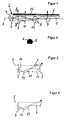
- the lighting device described below is part a signal lamp for motor vehicles, which as an additional raised brake light above one end Rear area of the motor vehicle can be arranged.
- the lighting device consists essentially of a rod-shaped light guide (1) in a not shown Housing is held.
- the rod-shaped light guide (1) instructs a first end arranged transversely to its longitudinal direction large-area front surface (2), which acts as a light coupling surface (3) is formed.
- the light coupling surface (3) can be flat or be slightly arched.
- Coaxial to that Light guide (1) is a light source (4) in the area of Light coupling surface (3) arranged, which preferably as Light-emitting diode (LED) is formed.
- LED Light-emitting diode
- the rod-shaped light guide (1) has one in the longitudinal direction light exit surface radiating transversely to its longitudinal axis (5) (6) on. On the light exit surface (6) opposite side of the light guide (1) is one Reflection surface (7) arranged. While the Light exit surface (6) runs parallel to the longitudinal axis (5), the distance between the light exit surface is reduced (6) and the reflective surface (7) from the end face (2) in Longitudinal direction to the opposite end of the light guide (1) stepwise.
- the reflection surface (7) is made on the one hand a first section (9) is formed, which is essentially extends parallel to the longitudinal axis (5).
- the Reflection surface (7) at an angle to the longitudinal axis (5) standing second section (10) together with the first Section (9) of the reflection surface (7) a step-shaped Gives contour.
- the second section (10) is as flat Inclined surface (11) formed with the longitudinal axis (5) obtuse angle ⁇ forms.
- the inclined surface (11) closes at one of the Light coupling surface (3) facing end of the first section (9) immediately.
- the inclined surface (11) is such formed that on one of the light coupling surface (3) facing end a bulge (12) is formed, the Distance to the opposite light exit surface (6) is greater than the distance of an imaginary extended line (13) of the bulge (12) immediately subsequent adjacent first section (9) to the corresponding opposite light exit surface (6).
- the Bulge (12) is formed on the one hand from which over the Line (13) outwardly extending inclined surface (11) and on the other hand one is at right angles from the sloping surface (11) adjoining distance section (14), which in the adjacent first section (9) merges.
- the first section (9), the second section (10) and the Spacer section (14) are each as flat surfaces trained so that the light guide (1) an approximately has circular cross-section.
- FIG 4 can be between the light coupling surface (3) opposite end of the first section (9) and the inclined surface (11) extending distance section also as a convex Spacer section (17) may be formed.
- the shape of the Spacer section (17) can also have other shapes that bring manufacturing advantages. Because of the Alignment of the spacer sections (14) or (17) none Total reflection of the light rays at the same occurs the shape of the spacer section is of minor importance. It is essential that they are in a radial area outside the extended line (13) of the adjacent first Extend section (9).
Landscapes
- Engineering & Computer Science (AREA)
- General Engineering & Computer Science (AREA)
- Physics & Mathematics (AREA)
- Optics & Photonics (AREA)
- General Physics & Mathematics (AREA)
- Microelectronics & Electronic Packaging (AREA)
- Non-Portable Lighting Devices Or Systems Thereof (AREA)
- Planar Illumination Modules (AREA)
- Lighting Device Outwards From Vehicle And Optical Signal (AREA)
Abstract
Description
- Figur 1:
- eine Seitenansicht einer Beleuchtungseinrichtung`
- Figur 2:
- einen Querschnitt der Beleuchtungseinrichtung entlang der Linie II-II in Figur 1,
- Figur 3:
- eine vergrößerte Teilansicht X aus Figur 1 und
- Figur 4:
- eine vergrößerte Teilansicht X aus Figur 1 nach einem alternativen Ausführungsbeispiel.
Claims (10)
- Beleuchtungseinrichtung für Kraftfahrzeuge, insbesondere für eine Signalleuchte, mit einem langgestreckten Lichtleiter, der eine sich quer zur Längsrichtung erstreckende Lichteinkoppelfläche aufweist und der in Längsrichtung eine quer zur Längsrichtung abstrahlende Lichtaustrittsfläche aufweist, wobei der Lichtaustrittsfläche gegenüberliegend eine Reflexionsfläche zugeordnet ist, die in Richtung auf das von der Lichteinkoppelfläche abgewandte Ende des Lichtleiters stufenförmig zu der Lichtaustrittsfläche hin ansteigt mit einer Anzahl von in Längsrichtung verlaufenden ersten Abschnitten und mit einer Anzahl von in einem Winkel zur Längsrichtung verlaufenden, zu den ersten Abschnitten benachbarten zweiten Abschnitten, dadurch gekennzeichnet, daß ein der Lichteinkoppelfläche (3) zugewandtes Ende des zweiten Abschnitts (10) als quer zur Längsrichtung abragende Ausbuchtung (12) ausgebildet ist.
- Beleuchtungseinrichtung nach Anspruch 1, dadurch gekennzeichnet, daß der Abstand zwischen der Oberfläche der Ausbuchtung (12) und der gegenüberliegenden Lichtaustrittsfläche (6) größer ist als der Abstand zwischen einer gedachten verlängerten Linie (13) des benachbarten ersten Abschnitts (9) zu der entsprechenden gegenüberliegenden Lichtaustrittsfläche (6).
- Beleuchtungseinrichtung nach Anspruch 1 oder 2, dadurch gekennzeichnet, daß die Ausbuchtung (12) aus einem der Lichteinkoppelfläche (3) zugewandten Teilbereich des zweiten Abschnitts (10) und einem sich demselben unmittelbar anschließenden, sich zum benachbarten Ende des ersten Abschnitts (9) erstreckenden Distanzabschnitt (14, 17) gebildet ist.
- Beleuchtungseinrichtung nach einem der Ansprüche 1 bis 3, dadurch gekennzeichnet, daß der zweite Abschnitt (10) als eine die Lichtstrahlen zur Lichtaustrittsfläche (6) hin reflektierende Schrägfläche (11) ausgebildet ist.
- Beleuchtungseinrichtung nach einem der Ansprüche 1 bis 4, dadurch gekennzeichnet, daß der Distanzabschnitt (14) rechtwinklig zu der Schrägfläche (11) angeordnet ist.
- Beleuchtungseinrichtung nach einem der Ansprüche 1 bis 4, dadurch gekennzeichnet, daß der Distanzabschnitt (17) konvex- oder konkavförmig ausgebildet ist, wobei sich mindestens ein Ende des Distanzabschnitts (17) stetig an ein Ende der Schrägfläche (11) und/oder des ersten Abschnitts (9) anschließt.
- Beleuchtungseinrichtung nach einem der Ansprüche 1 bis 6, dadurch gekennzeichnet, daß der Lichtleiter (1) stabförmig ausgebildet ist und daß sich die Lichtaustrittsfläche (6) quer zur Längsrichtung des Lichtleiters (1) bogenförmig erstreckt.
- Beleuchtungseinrichtung nach einem der Ansprüche 1 bis 7, dadurch gekennzeichnet, daß die Schrägfläche (11) mit einer Längsachse (5) des Lichtleiters (1) einen stumpfen Winkel α bildet.
- Beleuchtungseinrichtung nach einem der Ansprüche 1 bis 8, dadurch gekennzeichnet, daß die Ausbuchtung (12) eine solche Ausdehnung in Querrichtung des Lichtleiters (1) aufweist, daß Lichtstrahlen (16), die in einem dem zweiten Abschnitt (10) nahen Bereich des der Lichteinkoppelfläche (3) abgewandten Endes des ersten Abschnitts (9) reflektiert werden, erst an der gegenüberliegenden Lichtaustrittsfläche (6) als nächstes reflektiert werden.
- Beleuchtungseinrichtung nach einem der Ansprüche 1 bis 9, dadurch gekennzeichnet, daß der erste Abschnitt (9) und der zweite Abschnitt (10) jeweils eben ausgebildet sind.
Applications Claiming Priority (2)
| Application Number | Priority Date | Filing Date | Title |
|---|---|---|---|
| DE19806526 | 1998-02-17 | ||
| DE19806526A DE19806526A1 (de) | 1998-02-17 | 1998-02-17 | Beleuchtungseinrichtung für Kraftfahrzeuge |
Publications (3)
| Publication Number | Publication Date |
|---|---|
| EP0936403A2 true EP0936403A2 (de) | 1999-08-18 |
| EP0936403A3 EP0936403A3 (de) | 2001-10-24 |
| EP0936403B1 EP0936403B1 (de) | 2006-05-17 |
Family
ID=7858013
Family Applications (1)
| Application Number | Title | Priority Date | Filing Date |
|---|---|---|---|
| EP99102971A Expired - Lifetime EP0936403B1 (de) | 1998-02-17 | 1999-02-15 | Beleuchtungseinrichtung für Kraftfahrzeuge |
Country Status (2)
| Country | Link |
|---|---|
| EP (1) | EP0936403B1 (de) |
| DE (2) | DE19806526A1 (de) |
Cited By (7)
| Publication number | Priority date | Publication date | Assignee | Title |
|---|---|---|---|---|
| EP1184619A3 (de) * | 2000-08-30 | 2002-10-30 | Visteon Global Technologies, Inc. | Beleuchtungsanordnung mit Kantenbeleuchtung |
| WO2004042271A3 (de) * | 2002-11-07 | 2004-07-15 | Schefenacker Vision Systems | Lichtleiter für leuchten von fahrzeugen, vorzugsweise von kraftfahrzeugen |
| WO2005024477A1 (en) * | 2003-09-08 | 2005-03-17 | Koninklijke Philips Electronics N.V. | A light-guiding system comprising a plate-like light-emitting element |
| FR2986305A1 (fr) * | 2012-01-30 | 2013-08-02 | Automotive Lighting Rear Lamps France | Dispositif pour rendre homogene l'aspect d'un feu de signalisation de vehicule automobile |
| WO2015071620A1 (fr) | 2013-11-18 | 2015-05-21 | Automotive Lighting Rear Lamps France | Système d'éclairage et/ou de signalisation avec guides de lumiere pour vehicule |
| WO2015090822A1 (de) * | 2013-12-16 | 2015-06-25 | Automotive Lighting Reutlingen Gmbh | Kraftfahrzeugleuchte mit einem lichtleiter |
| US11719410B2 (en) | 2019-07-11 | 2023-08-08 | Dyson Technology Limited | Vehicle lamp assembly |
Families Citing this family (7)
| Publication number | Priority date | Publication date | Assignee | Title |
|---|---|---|---|---|
| DE19943821A1 (de) * | 1999-09-14 | 2001-03-15 | Valeo Beleuchtung Deutschland | Leuchte, insbesondere für Kraftfahrzeuge |
| DE10018284A1 (de) * | 2000-04-13 | 2001-10-18 | Valeo Beleuchtung Deutschland | Signalleuchte mit mindestens einem Leuchtmittel und einem Lichtleiter |
| DE10022420B4 (de) * | 2000-05-09 | 2007-04-26 | Automotive Lighting Reutlingen Gmbh | Fahrzeugleuchte |
| ES2168071B1 (es) | 2000-07-12 | 2003-07-16 | Barros Alejandro Rodriguez | Retrovisor modular con señales multiples intercambiables para vehiculos de 2, 3, 4 o mas ruedas. |
| DE20306739U1 (de) | 2003-04-30 | 2003-08-07 | Fer Fahrzeugelek K Gmbh | Fahrzeugleuchte |
| DE102012106025A1 (de) * | 2012-07-05 | 2014-01-09 | Hella Kgaa Hueck & Co. | Beleuchtungsvorrichtung für Fahrzeuge |
| US10648633B2 (en) | 2017-11-29 | 2020-05-12 | Toyota Motor Engineering & Manufacturing North America, Inc. | Lamp assemblies with multiple lighting functions sharing a cover lens |
Citations (3)
| Publication number | Priority date | Publication date | Assignee | Title |
|---|---|---|---|---|
| DE3047816C2 (de) | 1979-12-20 | 1987-10-15 | Cibie Projecteurs S.A., Bobigny, Fr | |
| DE3123369C2 (de) | 1981-06-12 | 1991-07-25 | Vdo Adolf Schindling Ag, 6000 Frankfurt, De | |
| DE3526511C2 (de) | 1984-07-26 | 1992-09-10 | Sharp K.K., Osaka, Jp |
Family Cites Families (13)
| Publication number | Priority date | Publication date | Assignee | Title |
|---|---|---|---|---|
| JPS5467454A (en) * | 1977-11-09 | 1979-05-30 | Nissan Motor | Meter with pointer |
| DE3147805A1 (de) * | 1981-12-03 | 1983-06-16 | Gisela 6000 Frankfurt Adam | Sicherheitsbeleuchtung fuer fahrzeuge |
| IT8552912U1 (it) * | 1985-01-28 | 1986-07-28 | Comind Spa | Fanale per autoveicoli. |
| DE4129094B4 (de) * | 1991-09-02 | 2005-08-25 | Hella Kgaa Hueck & Co. | Signalleuchte mit Leuchtdioden als Lichtquelle für Kraftfahrzeuge und deren Verwendung für unterschiedliche Signalleuchtenfunktionen |
| US5165772A (en) * | 1992-03-18 | 1992-11-24 | Hughes Aircraft Company | Visual display device |
| US5369554A (en) * | 1993-01-07 | 1994-11-29 | Ford Motor Company | Illuminator utilizing multiple light guides |
| US5434754A (en) * | 1993-12-27 | 1995-07-18 | Ford Motor Company | Light manifold |
| JP3286138B2 (ja) * | 1995-08-03 | 2002-05-27 | 日東電工株式会社 | 導光板、面光源装置、偏光光源装置及び液晶表示装置 |
| US5640483A (en) * | 1996-03-19 | 1997-06-17 | Ctx Opto-Electronics Corp. | Backlighting system utilizing total internal reflection |
| US5926601A (en) * | 1996-05-02 | 1999-07-20 | Briteview Technologies, Inc. | Stacked backlighting system using microprisms |
| DE19621148A1 (de) * | 1996-05-14 | 1997-12-04 | Magna Reflex Holding Gmbh | Leuchtelement |
| DE19638081A1 (de) * | 1996-09-19 | 1998-03-26 | Hella Kg Hueck & Co | Leuchte für Fahrzeuge |
| DE29716013U1 (de) * | 1997-09-06 | 1997-10-23 | Hella Kg Hueck & Co | Beleuchtungseinrichtung |
-
1998
- 1998-02-17 DE DE19806526A patent/DE19806526A1/de not_active Withdrawn
-
1999
- 1999-02-15 DE DE59913424T patent/DE59913424D1/de not_active Expired - Fee Related
- 1999-02-15 EP EP99102971A patent/EP0936403B1/de not_active Expired - Lifetime
Patent Citations (3)
| Publication number | Priority date | Publication date | Assignee | Title |
|---|---|---|---|---|
| DE3047816C2 (de) | 1979-12-20 | 1987-10-15 | Cibie Projecteurs S.A., Bobigny, Fr | |
| DE3123369C2 (de) | 1981-06-12 | 1991-07-25 | Vdo Adolf Schindling Ag, 6000 Frankfurt, De | |
| DE3526511C2 (de) | 1984-07-26 | 1992-09-10 | Sharp K.K., Osaka, Jp |
Cited By (13)
| Publication number | Priority date | Publication date | Assignee | Title |
|---|---|---|---|---|
| EP1184619A3 (de) * | 2000-08-30 | 2002-10-30 | Visteon Global Technologies, Inc. | Beleuchtungsanordnung mit Kantenbeleuchtung |
| WO2004042271A3 (de) * | 2002-11-07 | 2004-07-15 | Schefenacker Vision Systems | Lichtleiter für leuchten von fahrzeugen, vorzugsweise von kraftfahrzeugen |
| US7410280B2 (en) | 2002-11-07 | 2008-08-12 | Odelo Gmbh | Light guide for lighting vehicles, preferably motor vehicles |
| WO2005024477A1 (en) * | 2003-09-08 | 2005-03-17 | Koninklijke Philips Electronics N.V. | A light-guiding system comprising a plate-like light-emitting element |
| US7401964B2 (en) | 2003-09-08 | 2008-07-22 | Koninklijke Philips Electronics, N.V. | Light-guiding system comprising a plate-like light-emitting element |
| CN100416315C (zh) * | 2003-09-08 | 2008-09-03 | 皇家飞利浦电子股份有限公司 | 包含片状发光元件的光导系统 |
| FR2986305A1 (fr) * | 2012-01-30 | 2013-08-02 | Automotive Lighting Rear Lamps France | Dispositif pour rendre homogene l'aspect d'un feu de signalisation de vehicule automobile |
| WO2013113726A1 (fr) * | 2012-01-30 | 2013-08-08 | Automotive Lighting Rear Lamps France S.A.S. | Dispositif pour rendre homogene l'aspect d'un feu de signalisation de vehicule automobile |
| WO2015071620A1 (fr) | 2013-11-18 | 2015-05-21 | Automotive Lighting Rear Lamps France | Système d'éclairage et/ou de signalisation avec guides de lumiere pour vehicule |
| WO2015090822A1 (de) * | 2013-12-16 | 2015-06-25 | Automotive Lighting Reutlingen Gmbh | Kraftfahrzeugleuchte mit einem lichtleiter |
| CN105980770A (zh) * | 2013-12-16 | 2016-09-28 | 汽车照明罗伊特林根有限公司 | 具有光导体的机动车灯 |
| CN105980770B (zh) * | 2013-12-16 | 2019-04-05 | 汽车照明罗伊特林根有限公司 | 具有光导体的机动车灯 |
| US11719410B2 (en) | 2019-07-11 | 2023-08-08 | Dyson Technology Limited | Vehicle lamp assembly |
Also Published As
| Publication number | Publication date |
|---|---|
| DE59913424D1 (de) | 2006-06-22 |
| EP0936403A3 (de) | 2001-10-24 |
| EP0936403B1 (de) | 2006-05-17 |
| DE19806526A1 (de) | 1999-08-19 |
Similar Documents
| Publication | Publication Date | Title |
|---|---|---|
| EP0933587B1 (de) | Stabförmiger Lichtleiter | |
| EP1491815B1 (de) | Beleuchtungseinrichtung für ein Fahrzeug | |
| EP1640656B1 (de) | Lichtleiter für Leuchten, insbesondere für Leuchten von Kraftfahrzeugen | |
| EP1022187A2 (de) | Fahrzeugleuchte | |
| EP0936403B1 (de) | Beleuchtungseinrichtung für Kraftfahrzeuge | |
| DE19908961A1 (de) | Leuchte, insbesondere für Kraftfahrzeuge | |
| EP1195296A2 (de) | Seitenblinkleuchte | |
| EP1167869A2 (de) | Lichtleitelement | |
| DE10356483B4 (de) | Fahrzeugaußenspiegel-Leuchte eines Kraftfahrzeugs | |
| DE102004054732B4 (de) | Lichtleiteranordung | |
| EP1225385A2 (de) | Leuchte, insbesondere Signalleuchte, für Kraftfahrzeuge | |
| EP1055867B1 (de) | Stabförmiger Lichtleiter | |
| DE19803537A1 (de) | Leuchte für Fahrzeuge | |
| DE102007023076A1 (de) | Beleuchtungseinrichtung für Kraftfahrzeuge | |
| DE19943821A1 (de) | Leuchte, insbesondere für Kraftfahrzeuge | |
| DE10149044B4 (de) | Fahrzeugleuchte | |
| DE10135478B4 (de) | Beleuchtungseinrichtung | |
| EP1154198B1 (de) | Stabförmiger Lichtleiter | |
| DE102006037797B4 (de) | Kraftfahrzeugleuchte | |
| EP2269901B1 (de) | Balkenförmige Rückleuchte für ein Zweirad | |
| EP1146281B1 (de) | Signalleuchte mit mindestens einem Leuchtmittel und einem Lichtleiter | |
| DE20020544U1 (de) | Seitenblinkleuchte | |
| DE20013330U1 (de) | Kraftfahrzeugleuchte | |
| DE10317062A1 (de) | Beleuchtungseinrichtung für Kraftfahrzeuge | |
| EP1170545B1 (de) | Stabförmiger Lichtleiter |
Legal Events
| Date | Code | Title | Description |
|---|---|---|---|
| PUAI | Public reference made under article 153(3) epc to a published international application that has entered the european phase |
Free format text: ORIGINAL CODE: 0009012 |
|
| AK | Designated contracting states |
Kind code of ref document: A2 Designated state(s): AT BE CH CY DE DK ES FI FR GB GR IE IT LI LU MC NL PT SE Kind code of ref document: A2 Designated state(s): DE FR GB IT |
|
| AX | Request for extension of the european patent |
Free format text: AL;LT;LV;MK;RO;SI |
|
| PUAL | Search report despatched |
Free format text: ORIGINAL CODE: 0009013 |
|
| AK | Designated contracting states |
Kind code of ref document: A3 Designated state(s): AT BE CH CY DE DK ES FI FR GB GR IE IT LI LU MC NL PT SE |
|
| AX | Request for extension of the european patent |
Free format text: AL;LT;LV;MK;RO;SI |
|
| 17P | Request for examination filed |
Effective date: 20020326 |
|
| AKX | Designation fees paid |
Free format text: DE FR GB IT |
|
| RAP1 | Party data changed (applicant data changed or rights of an application transferred) |
Owner name: HELLA KGAA HUECK & CO. |
|
| GRAP | Despatch of communication of intention to grant a patent |
Free format text: ORIGINAL CODE: EPIDOSNIGR1 |
|
| GRAS | Grant fee paid |
Free format text: ORIGINAL CODE: EPIDOSNIGR3 |
|
| GRAA | (expected) grant |
Free format text: ORIGINAL CODE: 0009210 |
|
| AK | Designated contracting states |
Kind code of ref document: B1 Designated state(s): DE FR GB IT |
|
| PG25 | Lapsed in a contracting state [announced via postgrant information from national office to epo] |
Ref country code: IT Free format text: LAPSE BECAUSE OF FAILURE TO SUBMIT A TRANSLATION OF THE DESCRIPTION OR TO PAY THE FEE WITHIN THE PRESCRIBED TIME-LIMIT;WARNING: LAPSES OF ITALIAN PATENTS WITH EFFECTIVE DATE BEFORE 2007 MAY HAVE OCCURRED AT ANY TIME BEFORE 2007. THE CORRECT EFFECTIVE DATE MAY BE DIFFERENT FROM THE ONE RECORDED. Effective date: 20060517 Ref country code: GB Free format text: LAPSE BECAUSE OF FAILURE TO SUBMIT A TRANSLATION OF THE DESCRIPTION OR TO PAY THE FEE WITHIN THE PRESCRIBED TIME-LIMIT Effective date: 20060517 |
|
| REG | Reference to a national code |
Ref country code: GB Ref legal event code: FG4D Free format text: NOT ENGLISH |
|
| RIC1 | Information provided on ipc code assigned before grant |
Ipc: F21S 8/10 20060101ALI20060327BHEP Ipc: F21V 7/00 20060101AFI20060327BHEP |
|
| REF | Corresponds to: |
Ref document number: 59913424 Country of ref document: DE Date of ref document: 20060622 Kind code of ref document: P |
|
| GBV | Gb: ep patent (uk) treated as always having been void in accordance with gb section 77(7)/1977 [no translation filed] |
Effective date: 20060517 |
|
| ET | Fr: translation filed | ||
| PLBE | No opposition filed within time limit |
Free format text: ORIGINAL CODE: 0009261 |
|
| STAA | Information on the status of an ep patent application or granted ep patent |
Free format text: STATUS: NO OPPOSITION FILED WITHIN TIME LIMIT |
|
| 26N | No opposition filed |
Effective date: 20070220 |
|
| PGFP | Annual fee paid to national office [announced via postgrant information from national office to epo] |
Ref country code: DE Payment date: 20080207 Year of fee payment: 10 |
|
| PGFP | Annual fee paid to national office [announced via postgrant information from national office to epo] |
Ref country code: FR Payment date: 20080208 Year of fee payment: 10 |
|
| REG | Reference to a national code |
Ref country code: FR Ref legal event code: ST Effective date: 20091030 |
|
| PG25 | Lapsed in a contracting state [announced via postgrant information from national office to epo] |
Ref country code: DE Free format text: LAPSE BECAUSE OF NON-PAYMENT OF DUE FEES Effective date: 20090901 |
|
| PG25 | Lapsed in a contracting state [announced via postgrant information from national office to epo] |
Ref country code: FR Free format text: LAPSE BECAUSE OF NON-PAYMENT OF DUE FEES Effective date: 20090302 |