EP1491815B1 - Beleuchtungseinrichtung für ein Fahrzeug - Google Patents
Beleuchtungseinrichtung für ein Fahrzeug Download PDFInfo
- Publication number
- EP1491815B1 EP1491815B1 EP04014811A EP04014811A EP1491815B1 EP 1491815 B1 EP1491815 B1 EP 1491815B1 EP 04014811 A EP04014811 A EP 04014811A EP 04014811 A EP04014811 A EP 04014811A EP 1491815 B1 EP1491815 B1 EP 1491815B1
- Authority
- EP
- European Patent Office
- Prior art keywords
- light
- light guide
- length
- lighting apparatus
- output elements
- Prior art date
- Legal status (The legal status is an assumption and is not a legal conclusion. Google has not performed a legal analysis and makes no representation as to the accuracy of the status listed.)
- Expired - Lifetime
Links
- 230000003287 optical effect Effects 0.000 claims description 42
- 230000002093 peripheral effect Effects 0.000 claims description 11
- 230000008878 coupling Effects 0.000 abstract description 22
- 238000010168 coupling process Methods 0.000 abstract description 22
- 238000005859 coupling reaction Methods 0.000 abstract description 22
- 239000004020 conductor Substances 0.000 abstract description 3
- 230000007423 decrease Effects 0.000 description 6
- 238000005286 illumination Methods 0.000 description 5
- 238000004519 manufacturing process Methods 0.000 description 3
- 239000013307 optical fiber Substances 0.000 description 3
- 239000000463 material Substances 0.000 description 2
- 230000003746 surface roughness Effects 0.000 description 2
- 238000010276 construction Methods 0.000 description 1
- 230000008094 contradictory effect Effects 0.000 description 1
- 230000003247 decreasing effect Effects 0.000 description 1
- 238000000605 extraction Methods 0.000 description 1
- 239000003973 paint Substances 0.000 description 1
- 230000005855 radiation Effects 0.000 description 1
Images


Classifications
-
- G—PHYSICS
- G02—OPTICS
- G02B—OPTICAL ELEMENTS, SYSTEMS OR APPARATUS
- G02B6/00—Light guides; Structural details of arrangements comprising light guides and other optical elements, e.g. couplings
- G02B6/0001—Light guides; Structural details of arrangements comprising light guides and other optical elements, e.g. couplings specially adapted for lighting devices or systems
- G02B6/0005—Light guides; Structural details of arrangements comprising light guides and other optical elements, e.g. couplings specially adapted for lighting devices or systems the light guides being of the fibre type
- G02B6/001—Light guides; Structural details of arrangements comprising light guides and other optical elements, e.g. couplings specially adapted for lighting devices or systems the light guides being of the fibre type the light being emitted along at least a portion of the lateral surface of the fibre
-
- F—MECHANICAL ENGINEERING; LIGHTING; HEATING; WEAPONS; BLASTING
- F21—LIGHTING
- F21S—NON-PORTABLE LIGHTING DEVICES; SYSTEMS THEREOF; VEHICLE LIGHTING DEVICES SPECIALLY ADAPTED FOR VEHICLE EXTERIORS
- F21S43/00—Signalling devices specially adapted for vehicle exteriors, e.g. brake lamps, direction indicator lights or reversing lights
- F21S43/10—Signalling devices specially adapted for vehicle exteriors, e.g. brake lamps, direction indicator lights or reversing lights characterised by the light source
- F21S43/13—Signalling devices specially adapted for vehicle exteriors, e.g. brake lamps, direction indicator lights or reversing lights characterised by the light source characterised by the type of light source
- F21S43/14—Light emitting diodes [LED]
-
- F—MECHANICAL ENGINEERING; LIGHTING; HEATING; WEAPONS; BLASTING
- F21—LIGHTING
- F21S—NON-PORTABLE LIGHTING DEVICES; SYSTEMS THEREOF; VEHICLE LIGHTING DEVICES SPECIALLY ADAPTED FOR VEHICLE EXTERIORS
- F21S43/00—Signalling devices specially adapted for vehicle exteriors, e.g. brake lamps, direction indicator lights or reversing lights
- F21S43/20—Signalling devices specially adapted for vehicle exteriors, e.g. brake lamps, direction indicator lights or reversing lights characterised by refractors, transparent cover plates, light guides or filters
- F21S43/235—Light guides
- F21S43/236—Light guides characterised by the shape of the light guide
- F21S43/237—Light guides characterised by the shape of the light guide rod-shaped
-
- F—MECHANICAL ENGINEERING; LIGHTING; HEATING; WEAPONS; BLASTING
- F21—LIGHTING
- F21S—NON-PORTABLE LIGHTING DEVICES; SYSTEMS THEREOF; VEHICLE LIGHTING DEVICES SPECIALLY ADAPTED FOR VEHICLE EXTERIORS
- F21S43/00—Signalling devices specially adapted for vehicle exteriors, e.g. brake lamps, direction indicator lights or reversing lights
- F21S43/20—Signalling devices specially adapted for vehicle exteriors, e.g. brake lamps, direction indicator lights or reversing lights characterised by refractors, transparent cover plates, light guides or filters
- F21S43/235—Light guides
- F21S43/242—Light guides characterised by the emission area
- F21S43/245—Light guides characterised by the emission area emitting light from one or more of its major surfaces
-
- F—MECHANICAL ENGINEERING; LIGHTING; HEATING; WEAPONS; BLASTING
- F21—LIGHTING
- F21S—NON-PORTABLE LIGHTING DEVICES; SYSTEMS THEREOF; VEHICLE LIGHTING DEVICES SPECIALLY ADAPTED FOR VEHICLE EXTERIORS
- F21S43/00—Signalling devices specially adapted for vehicle exteriors, e.g. brake lamps, direction indicator lights or reversing lights
- F21S43/20—Signalling devices specially adapted for vehicle exteriors, e.g. brake lamps, direction indicator lights or reversing lights characterised by refractors, transparent cover plates, light guides or filters
- F21S43/235—Light guides
- F21S43/247—Light guides with a single light source being coupled into the light guide
-
- F—MECHANICAL ENGINEERING; LIGHTING; HEATING; WEAPONS; BLASTING
- F21—LIGHTING
- F21Y—INDEXING SCHEME ASSOCIATED WITH SUBCLASSES F21K, F21L, F21S and F21V, RELATING TO THE FORM OR THE KIND OF THE LIGHT SOURCES OR OF THE COLOUR OF THE LIGHT EMITTED
- F21Y2115/00—Light-generating elements of semiconductor light sources
- F21Y2115/10—Light-emitting diodes [LED]
Definitions
- the invention relates to a lighting device for a vehicle, in particular a signal light, with at least one light source and at least one arranged with its Lichteinkoppel requirements in Lichtabstrahl Colour
- the light rod rod-shaped light guide having at its outer periphery a plurality of extension direction of the optical fiber mutually offset optical Auskoppeliano, in which within the Light guide incident thereon light is reflected such that it exits at a respective output element opposite the peripheral region of the light guide therefrom, wherein mutually adjacent juxtaposed decoupling in the extension direction of the light guide are each spaced by a auskoppelelementELI intermediate area.
- Such a lighting device is off DE 198 04 440 A1 known. It has a rod-shaped optical waveguide which has a strip-shaped region extending in the longitudinal extension direction of the optical waveguide in which a plurality of prisms are arranged, at which the light guided in the optical waveguide is deflected in such a way that it is opposite to the relevant prism Peripheral region of the light guide emerges from this. Neighboring prisms are each spaced apart in the longitudinal direction of extension of the light guide, the distances being constant over the length of the light guide. The dimension which the prisms have in the longitudinal extension direction of the optical waveguide is also constant along the longitudinal axis of the optical waveguide.
- the prisms Transverse to the longitudinal extent of the light guide, the prisms have a width which varies in the direction of the longitudinal extent of the light guide. In this case, the width, starting from the light coupling surface toward the opposite end of the light guide, increases in such a way that the light quantity coupled out over the length of the light guide is approximately constant.
- the illumination device has the disadvantage that, due to the different widths which the prisms have along the light guide, the emission angle at which the light guided in the light guide emerges therefrom varies.
- the emission angle starting from the light coupling surface to the opposite end of the light guide towards, so that despite the about the length of the light guide approximately constant decoupled amount of light, when viewing the light guide from a certain direction, the brightness of the light decreases with increasing distance from the light input surface ,
- This is particularly disadvantageous in a signal light in which due to legal Provisions, when viewing the light guide from a particular direction, for example, in a view of the back of a vehicle along the light guide a predetermined luminance distribution must be achieved.
- a lighting device for indirect illumination of a vehicle interior which has a rod-shaped light guide, in which the arranged at the periphery of the light guide optical coupling elements along the light guide at different distances from one another.
- a uniform brightness distribution can be achieved along the light guide by this measure, such a lighting device is only conditionally suitable as a signal light because the light guide has an uneven appearance both when the illumination device is switched on and when the illumination device is switched off.
- the light guide should nevertheless have a uniform appearance.
- the length, which have the intermediate regions in the direction of extension of the light guide and the length which have the coupling elements in the extension direction of the light guide in the extension direction of the light guide in each case vary such that the length of each of a coupling element and a in Extending direction of the light guide adjacent thereto intermediate region formed sections is approximately constant.
- the length of the coupling-out elements therefore increases along the light guide in each case to the extent (decreases), in which decreases the length of the intermediate regions adjacent to the coupling-out elements (increases).
- the length of the coupling-out elements can be selected in the manufacture or construction of the light guide according to the respective brightness to be coupled out of the light guide, so that a desired brightness distribution can be adjusted in a simple manner along the longitudinal extent of the light guide.
- the light guide has a uniform despite the different length decoupling elements Appearance, since the sum of the length of a decoupling element and the length of an adjacent intermediate region in the extension direction of the light guide remains approximately constant and thus the decoupling elements are arranged in a constant, uniform grid.
- the width of the outcoupling elements present transversely to the longitudinal extension of the optical waveguide can be constant along the longitudinal extension direction of the optical waveguide, so that the emission angle of the light emitted by the optical waveguide is approximately in planes oriented at right angles to the longitudinal axis of the optical waveguide and spaced apart on the longitudinal central axis of the optical waveguide is constant.
- the width of the coupling-out elements in the longitudinal extension direction of the optical waveguide varies if along the optical waveguide a different width of light emission is desired.
- the length of the coupling-out elements increases with increasing distance from the light coupling surface such that the brightness of the light emerging from the light guide increases with increasing distance from the light coupling surface.
- the brightness of the light guide thus decreases, instead of decreasing, the amount of light present in the light guide with the distance from the light input surface.
- the light guide has a deviating from a straight line, preferably adapted to the shape of a vehicle outer skin, in particular arcuately curved course.
- the light guide can then be guided in the position of use, for example in the horizontal direction arcuately around a corner of a vehicle, wherein the light source can be arranged on a longitudinal side of the vehicle, for example on the fender.
- the length of the decoupling elements entlag the light guide is selected accordingly - most of the light on a transverse to the longitudinal side arranged vehicle side, for example, be coupled out of the light guide at the front or back of the vehicle. This is particularly advantageous in signal lights that have to radiate due to legal requirements substantially in or against the forward direction of travel of the vehicle.
- the optical outcoupling elements are formed such that the incident within the light guide light is subject to total reflection, and that the decoupling elements are preferably prisms, which optionally formed symmetrical with respect to a plane extending transversely to the longitudinal extent of the light guide are.
- the decoupling elements are preferably prisms, which optionally formed symmetrical with respect to a plane extending transversely to the longitudinal extent of the light guide are.
- the light incoupling surface is arranged on at least one end face of the light guide, and if the light incoupling surface is preferably provided on a substantially outcoupling element-free light guide coupling section, at which the cross section of the light guide, starting from the light input surface to the remote end of the coupling section so preferably parabolic expands that guided in the light guide light impinges on the peripheral wall of the coupling-in section under total reflection conditions.
- the light can then be transported even more loss-less in the light guide from the light coupling surface to the coupling-out of the light guide.
- the decoupling elements are arranged within a strip-shaped region extending substantially in its longitudinal direction on the outer circumference of the optical waveguide.
- the strip-shaped region allows a cost-effective production of the light guide, in which the contour of the coupling elements can be produced for example by wire sheaths.
- the strip-shaped region may be formed as an optical shoulder. At one of the light guide associated with the luminaire housing can then be provided for matching the optics shoulder receptacle to facilitate the positioning and alignment of the light guide to the luminaire housing during assembly.
- the strip-shaped region has a component extending in the circumferential direction of the optical waveguide and, in particular, is guided around the waveguide along a helix.
- This embodiment is particularly advantageous in light guides that are curved three-dimensionally in space.
- the strip-shaped region of the light guide having the outcoupling elements can have at least one interruption.
- the interruption can be covered in a designed as a tail lamp lighting device, for example, by a reflector or an element for another lighting function.
- the optical waveguide has on its outer circumference at least two strip-shaped regions with decoupling elements arranged offset to one another in the circumferential direction of the optical waveguide, wherein the strip-shaped regions are optionally spaced apart transversely to the longitudinal extension of the optical waveguide.
- At least the peripheral region of the optical waveguide, at which the light guided inside the optical waveguide emerges from this, is coated with a transparent ink layer.
- the core of the light guide is preferably made of a crystal-clear material that allows a good light pipe.
- the light guide can be encapsulated in its manufacture with the material of the paint layer.
- At least the peripheral region of the optical waveguide, at which the light guided inside the optical waveguide emerges from this, may have a surface roughness.
- the surface roughness also causes a certain scattering of the coupled out of the light guide light.
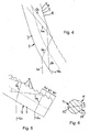
- FIG. 1 As a whole denoted by 1, designed as a signal light illumination device for a vehicle has as lighting means 2, a light emitting diode, which faces with its emission side of a arranged on an end face of a rod-shaped light guide 3 light input surface 4.
- the light source 2 and the light guide 3 are arranged on a light housing, not shown in detail in the drawing, which has attachment points for connection to the body of the vehicle and serves as a support for the light source 2 and the light guide 3.
- the optical waveguide 3 has on its outer circumference a strip-shaped region extending in the longitudinal direction of the optical waveguide 3, in which a multiplicity of optical decoupling elements 5 are arranged next to one another in the longitudinal direction of extension of the optical waveguide 3.
- a multiplicity of optical decoupling elements 5 are arranged next to one another in the longitudinal direction of extension of the optical waveguide 3.
- Adjacent to each other adjacent decoupling elements 5 are spaced apart in the longitudinal direction of the light guide 3 by an intermediate region 8, in which no decoupling element 5 is arranged.
- light beams 6 b When hitting the intermediate areas 8 guided in the light guide 3 light beams 6 b are deflected so that they impinge on a respective intermediate region 8 opposite peripheral region of the light guide 3 and are reflected back to this under total reflection conditions in the interior of the light guide 3.
- Fig. 1 to 3 takes the length A, which have the decoupling elements 5 in the longitudinal direction of the optical fiber 3, starting from the light input surface 4 to the end remote from the optical fiber 3 toward.
- the length Z which have the intermediate regions 8 in the longitudinal extension direction of the optical waveguide 3, decreases starting from the light coupling surface 4 to the end of the optical waveguide 3 remote therefrom.
- the increase in the length A of the decoupling elements 5 corresponds in each case to the decrease in the length Z of the intermediate regions 5, such that the length L of the sections formed in each case from a decoupling element 5 and an intermediate region 8 adjoining in the extension direction of the optical waveguide 3 in the longitudinal direction of the optical waveguide 3 in which the decoupling elements 5 having portion of the light guide 3 is constant.
- the light guide 3 has an arcuately curved course. In the position of use of the light guide 3 is guided around in a horizontal plane about a corner region of a vehicle rear, wherein the bulb 2 and the end portion of the light guide 3, on which the light input surface 4 is arranged, respectively on the left or right side of the vehicle and the opposite end portion of the light guide. 3 are arranged at the rear of the vehicle. Despite this sweep, the light guide 3 radiates substantially toward the rear of the vehicle. This is achieved in that a greater amount of light is coupled out of the light guide 3 at the end region of the light guide 3 which is remote from the light source 2 than at the end region which is adjacent to the light source 2.
- the length Z of For this purpose, intermediate regions 8 are reduced to zero at the end region of the optical waveguide 3 which is at a distance from the light incoupling surface 4, so that practically all of the light still contained in the optical waveguide 3 is decoupled therefrom.
- the light guide 3 at its the illuminant 2 end portion facing a coupling-9, on the front side of the light coupling surface 4 is arranged.
- the coupling-in section 9 has no decoupling elements 5. It can clearly be seen that the cross section of the light guide 3, starting from the light input surface 4 to the far end of the coupling portion 9 approximately parabolic widens, such that the light coupled by the light input surface 4 in the light guide 3 light under total reflection conditions on the peripheral wall of the coupling-in section 9 impinges and, in the further course of the optical waveguide 3, also upon impact with the intermediate regions 8 and / or the decoupling elements 5 is subject to total reflection.
- the decoupling elements 5 are each formed as prisms, which are oriented with their axis transverse to the longitudinal extent of the optical waveguide 3, approximately at right angles.
- Fig. 1 It can be seen that the axes of the prisms are approximately parallel to each other.
- the prisms are formed as projections, which protrude radially over the planes of the respectively adjacent intermediate regions 8.
- Fig. 5 It can be seen that, at the end region of the light guide 3 remote from the light incoupling surface 4, the oblique surfaces of the prisms facing the light incidence surface 4 are inclined more strongly with respect to the longitudinal center axis of the light guide 3 than the oblique surfaces of the prisms facing away from the light incidence surface 4.
- a particularly high proportion of the light guided in the light guide 3 is coupled out of the light guide at the peripheral region 7.
- Fig. 2 and 4 It can be seen that in a light conductor section located approximately centrally between the end faces of the light guide and in a region of the light guide 3 located between this section and the coupling section 9, the prisms are approximately symmetrical with respect to a plane extending normal to the longitudinal extension of the light guide 3.
- the light guide 3 is formed symmetrically with respect to a longitudinal center plane 10 and is approximately semi-circularly rounded in its half spaced from the outcoupling elements 5 half.
- the other, the coupling elements 5 having half of the light guide 3 is approximately trapezoidal.
- At the axial ends of the Decoupling elements 5 is formed on both sides of the longitudinal center plane 10 each have an optical shoulder 11.
Landscapes
- Physics & Mathematics (AREA)
- Engineering & Computer Science (AREA)
- General Engineering & Computer Science (AREA)
- Optics & Photonics (AREA)
- General Physics & Mathematics (AREA)
- Microelectronics & Electronic Packaging (AREA)
- Non-Portable Lighting Devices Or Systems Thereof (AREA)
- Planar Illumination Modules (AREA)
- Lighting Device Outwards From Vehicle And Optical Signal (AREA)
Description
- Die Erfindung betrifft eine Beleuchtungseinrichtung für ein Fahrzeug, insbesondere eine Signalleuchte, mit mindestens einem Leuchtmittel und zumindest einem mit seiner Lichteinkoppelfläche im Lichtabstrahlbereich des Leuchtmittels angeordneten stabförmigen Lichtleiter, der an seinem Außenumfang mehrere in Erstreckungsrichtung des Lichtleiters zueinander versetzte optische Auskoppelelemente aufweist, an denen innerhalb des Lichtleiters darauf auftreffendes Licht derart reflektiert wird, dass es an einem dem betreffenden Auskoppelelement gegenüberliegenden Umfangsbereich des Lichtleiters aus diesem austritt, wobei zueinander benachbart nebeneinander angeordnete Auskoppelelemente in Erstreckungsrichtung des Lichtleiters jeweils durch einen auskoppelelementfreien Zwischenbereich voneinander beabstandet sind.
- Eine derartige Beleuchtungseinrichtung ist aus
DE 198 04 440 A1 bekannt. Sie weist einen stabförmigen Lichtleiter auf, der an seinem Umfang einen in Längserstreckungsrichtung des Lichtleiters verlaufenden streifenförmigen Bereich aufweist, in dem eine Vielzahl von Prismen angeordnet sind, an denen das in dem Lichtleiter geführte Licht derart umgelenkt wird, dass es an einem dem betreffenden Prisma gegenüberliegenden Umfangsbereich des Lichtleiters aus diesem austritt. Zueinander benachbart angeordnete Prismen sind jeweils in Längserstreckungsrichtung des Lichtleiters voneinander beabstandet, wobei die Abstände über die Länge des Lichtleiters konstant sind. Auch die Abmessung, weiche die Prismen in Längserstreckungsrichtung des Lichtleiters aufweisen, ist entlang der Längsachse des Lichtleiters konstant. Quer zur Längserstreckung des Lichtleiters weisen die Prismen eine Breite auf, die in Richtung der Längserstreckung des Lichtleiters variiert. Dabei nimmt die Breite, ausgehend von der Lichteinkoppelfläche zum gegenüberliegenden Ende des Lichtleiters hin derart zu, dass die über die Länge des Lichtleiters aus diesem ausgekoppelte Lichtmenge in etwa konstant ist. Die Beleuchtungseinrichtung hat jedoch den Nachteil, dass durch die unterschiedliche Breite, welche die Prismen entlang des Lichtleiters aufweisen, der Abstrahlwinkel, unter dem das in dem Lichtleiter geführte Licht aus diesem austritt, variiert. Dabei nimmt der Abstrahlwinkel, ausgehend von der Lichteinkoppelfläche zum gegenüberliegenden Ende des Lichtleiters hin zu, so dass trotz der über die Länge des Lichtleiters etwa konstanten ausgekoppelten Lichtmenge, bei Betrachtung des Lichtleiters aus einer bestimmten Richtung die Helligkeit des Lichts mit zunehmendem Abstand von der Lichteinkoppelfläche abnimmt. Dies ist insbesondere bei einer Signalleuchte nachteilig, bei der aufgrund von gesetzlichen Bestimmungen, bei Betrachtung des Lichtleiters aus einer bestimmten Richtung, beispielsweise bei einer Ansicht auf die Rückseite eines Fahrzeugs, entlang des Lichtleiters eine vorgegebene Leuchtdichteverteilung erreicht werden muss. - Aus
DE 200 19 073 U1 ist ferner eine Beleuchtungseinrichtung zum indirekten Beleuchten eines Fahrzeuginnenraums bekannt, die einen stabförmigen Lichtleiter hat, bei dem die am Umfang des Lichtleiters angeordneten optischen Auskoppelelemente entlang des Lichtleiters unterschiedliche Abstände zueinander aufweisen. Durch diese Maßnahme lässt sich zwar entlang des Lichtleiters eine gleichmäßige Helligkeitsverteilung erreichen, jedoch ist eine derartige Beleuchtungseinrichtung als Signalleuchte nur bedingt geeignet, weil der Lichtleiter sowohl bei eingeschalteter als auch bei ausgeschalteter Beleuchtungseinrichtung aufgrund der unterschiedlichen Abstände der Auskoppelelemente ein ungleichmäßiges Erscheinungsbild aufweist. - Es besteht deshalb die Aufgabe, eine Beleuchtungseinrichtung der eingangs genannten Art zu schaffen, die in Erstreckungsrichtung des Lichtleiters eine von der in dem Lichtleiter jeweils vorhandenen Lichtmenge abweichende Helligkeitsverteilung des aus dem Lichtleiter ausgekoppelten Lichts ermöglicht. Dabei soll der Lichtleiter dennoch ein gleichmäßiges Erscheinungsbild aufweisen.
- Diese Aufgabe wird dadurch gelöst, dass die Länge, welche die Zwischenbereiche in Erstreckungsrichtung des Lichtleiters aufweisen und die Länge, welche die Auskoppelelemente in Erstreckungsrichtung des Lichtleiters aufweisen, in Erstreckungsrichtung des Lichtleiters jeweils derart variieren, dass die Länge der jeweils aus einem Auskoppelelement und einem in Erstreckungsrichtung des Lichtleiters daran angrenzenden Zwischenbereich gebildeten Abschnitte etwa konstant ist.
- Die Länge der Auskoppelelemente nimmt also entlang des Lichtleiters jeweils in dem Maße zu (ab), in dem die Länge der zu den Auskoppelelementen jeweils benachbarten Zwischenbereiche abnimmt (zunimmt). Somit kann die Länge der Auskoppelelemente bei der Herstellung oder Konstruktion des Lichtleiters entsprechend der jeweils einzustellenden Helligkeit des aus dem Lichtleiter auszukoppelnden Lichts gewählt werden, so dass auf einfache Weise entlang der Längserstreckung des Lichtleiters eine gewünschte Helligkeitsverteilung eingestellt werden kann. In scheinbar widersprüchlicher Weise weist der Lichtleiter trotz der unterschiedlich langen Auskoppelelemente ein gleichmäßiges Erscheinungsbild auf, da die Summe der Länge eines Auskoppelelements und der Länge eines daran angrenzenden Zwischenbereichs in Erstreckungsrichtung des Lichtleiters jeweils in etwa konstant bleibt und somit die Auskoppelelemente in einem konstanten, gleichmäßigen Raster angeordnet sind. Die quer zur Längserstreckung des Lichtleiters vorhandene Breite der Auskoppelelemente kann entlang der Längserstreckungsrichtung des Lichtleiters konstant sein, so dass der Abstrahlwinkel des von dem Lichtleiter abgestrahlten Lichts in Ebenen, die rechtwinklig zur Längsachse des Lichtleiters orientiert und auf der Längsmittelachse des Lichtleiters voneinander beabstandet sind, etwa konstant ist. Selbstverständlich ist es aber auch möglich, dass zusätzlich zu der Länge der Auskoppelelemente auch die Breite der Auskoppelelemente in Längserstreckungsrichtung des Lichtleiters variiert, wenn entlang des Lichtleiters eine unterschiedlich breite Lichtabstrahlung gewünscht wird.
- Besonders vorteilhaft ist, wenn die Länge der Auskoppelelemente mit zunehmendem Abstand von der Lichteinkoppelfläche derart zunimmt, dass die Helligkeit des aus dem Lichtleiter austretenden Lichts mit zunehmendem Abstand von der Lichteinkoppelfläche zunimmt. Die Helligkeit des Lichtleiters nimmt also entgegen der in dem Lichtleiter vorhandenen Lichtmenge mit der Entfernung von der Lichteinkoppelfläche zu statt ab. Dadurch ist es beispielsweise möglich, bei einer Signalleuchte, deren Lichtleiter eine Pfeilung aufweist, bei Betrachtung aus einer bestimmten Richtung entlang der Projektion des Lichtleiters in diese Richtung das Licht mit einer etwa konstanten Helligkeit aus dem Lichtleiter auszukoppeln.
- Vorteilhaft ist, wenn der Lichtleiter einen von einer geraden Linie abweichenden, vorzugsweise an die Form einer Fahrzeugaußenhaut angepassten, insbesondere bogenförmig gekrümmten Verlauf aufweist. Der Lichtleiter kann dann in Gebrauchsstellung beispielsweise in horizontaler Richtung bogenförmig um eine Ecke eines Fahrzeugs herumgeführt sein, wobei das Leuchtmittel an einer Längsseite des Fahrzeugs, beispielsweise am Kotflügel angeordnet sein kann. Dennoch kann - wenn die Länge der Auskoppelelemente entlag des Lichtleiters entsprechend gewählt ist - der größte Teil des Lichts an einer quer zu der Längsseite angeordneten Fahrzeugseite, beispielsweise an der Vorder- oder Rückseite des Fahrzeugs aus dem Lichtleiter ausgekoppelt werden. Dies ist vor allem bei Signalleuchten vorteilhaft, die aufgrund gesetzlicher Vorgaben im Wesentlichen in oder entgegen der Vorwärtsfahrtrichtung des Fahrzeugs abstrahlen müssen.
- Bei einer zweckmäßigen Ausgestaltung der Erfindung ist vorgesehen, dass die optischen Auskoppelelemente derart ausgebildet sind, dass das innerhalb des Lichtleiters darauf auftreffende Licht der Totalreflexion unterliegt, und dass die Auskoppelelemente vorzugsweise Prismen sind, die gegebenenfalls symmetrisch bezüglich einer quer zur Längserstreckung des Lichtleiters verlaufenden Ebene ausgebildet sind. Durch diese Maßnahme(n) kann das Licht weitgehend verlustfrei von der Lichteinkoppelfläche zu der Auskoppelstelle des Lichtleiters geführt werden. Auch wird eine unerwünschte Lichtauskopplung durch die Auskoppelelemente zur der Rückseite des Lichtleiters vermieden.
- Vorteilhaft ist, wenn die Lichteinkoppelfläche an wenigstens einer Stirnseite des Lichtleiters angeordnet ist, und wenn die Lichteinkoppelfläche vorzugsweise an einem im wesentlichen auskoppelelementfreien Lichtleiter-Einkoppelabschnitt vorgesehen ist, an dem sich der Querschnitt des Lichtleiters, ausgehend von der Lichteinkoppelfläche zu dem davon entfernten Ende des Einkoppelabschnitts derart vorzugsweise parabelförmig aufweitet, dass das in dem Lichtleiter geführte Licht unter Totalreflexionsbedingungen auf die Umfangswand des Einkoppelabschnitts auftrifft. Das Licht kann dann in dem Lichtleiter noch verlustarmer von der Lichteinkoppelfläche zu der Auskoppelstelle des Lichtleiters transportiert werden.
- Bei einer vorteilhaften Ausführungsform der Erfindung sind die Auskoppelelemente innerhalb eines sich am Außenumfang des Lichtleiters im Wesentlichen in dessen Längsrichtung erstreckenden streifenförmigen Bereiches angeordnet. Der streifenförmige Bereich ermöglicht eine kostengünstige Fertigung der Lichtleiter, bei welcher die Kontur der Auskoppelelemente beispielsweise durch Drahtscheiden hergestellt werden kann. Der streifenförmige Bereich kann als Optikschulter ausgebildet sein. An einem dem Lichtleiter zugeordneten Leuchtengehäuse kann dann eine zu der Optikschulter passende Aufnahme vorgesehen sein, um bei der Montage die Positionierung und Ausrichtung des Lichtleiters an dem Leuchtengehäuse zu erleichtern.
- Bei einer zweckmäßigen Ausführungsform der Erfindung weist der streifenförmige Bereich eine in Umfangsrichtung des Lichtleiters verlaufende Komponente auf und ist insbesondere entlang einer Wendel um den Lichtleiter herumgeführt. Diese Ausführungsform ist vor allem bei Lichtleitern vorteilhaft, die dreidimensional im Raum gekrümmt sind.
- Der die Auskoppelelemente aufweisende streifenförmige Bereich des Lichtleiters kann wenigstens eine Unterbrechung aufweisen. Die Unterbrechung kann bei einer als Rückleuchte ausgebildeten Beleuchtungseinrichtung beispielsweise durch einen Rückstrahler oder ein Element für eine andere Leuchtenfunktion überdeckt sein.
- Bei einer vorteilhaften Ausführungsform weist der Lichtleiter an seinem Außenumfang wenigstens zwei in Umfangsrichtung des Lichtleiters versetzt zueinander angeordnete streifenförmige Bereiche mit Auskoppelelementen auf, wobei die streifenförmigen Bereiche gegebenenfalls quer zur Längserstreckung des Lichtleiters voneinander beabstandet sind. Dadurch kann in einer Ebene, die quer zur Längserstreckung des Lichtleiters angeordnet ist, eine breitere Abstrahlcharakteristik des aus dem Lichtleiter ausgekoppelten Lichts erreicht werden. Dies ist insbesondere bei Lichtleitern vorteilhaft, die in Gebrauchsstellung im Wesentlichen in vertikaler Richtung verlaufen. Eine derartige Beleuchtungseinrichtung kann beispielsweise an der Rückseite einer C-Säule eines Kraftfahrzeugs angeordnet sein. Die Streifen können abschnittweise oder über ihre gesamte Länge die gleiche oder eine unterschiedliche Variation der Länge ihrer Auskoppelelemente aufweisen.
- Bei einer Ausführungsform der Erfindung ist vorgesehen, dass zumindest der Umfangsbereich des Lichtleiters, an dem das innerhalb des Lichtleiters geführte Licht aus diesem austritt, mit einer transparenten Farbschicht beschichtet ist. Der Kern des Lichtleiters besteht dabei vorzugsweise aus einem glasklaren Material, das eine gute Lichtleitung ermöglicht. Der Lichtleiter kann bei seiner Herstellung mit dem Werkstoff der Farbschicht umspritzt werden.
- Erwähnt werden soll noch, dass zumindest der Umfangsbereich des Lichtleiters, an dem das innerhalb des Lichtleiters geführte Licht aus diesem austritt, eine Oberflächenrauhigkeit aufweisen kann. Dadurch kann entlang des Lichtleiters eine noch gleichmäßigere Lichtabgabe erreicht werden. Allerdings bewirkt die Oberflächenrauhigkeit auch eine gewisse Streuung des aus dem Lichtleiter ausgekoppelten Lichts.
- Nachfolgend ist ein Ausführungsbeispiel der Erfindung anhand der Zeichnung näher erläutert. Es zeigen:
- Fig. 1
- eine Seitenansicht auf einer Rückleuchte für ein Fahrzeug, die einen stabförmigen Lichtleiter und als Leuchtmittel eine Leuchtdiode aufweist, wobei das aus dem Lichtleiter entgegen der Vorwärtsfahrtrichtung des Fahrzeugs ausgekoppelte Licht durch Pfeile dargestellt ist,
- Fig. 2
- eine vergrößerte Darstellung des in
Fig. 1 mit II bezeichneten Bereichs der Rückleuchte, wobei beispielhaft auch zwei Lichtstrahlen dargestellt sind, - Fig. 3
- eine vergrößerte Darstellung des in
Fig. 1 mit III bezeichneten Lichtleiterbereichs, - Fig. 4
- eine vergrößerte Darstellung des in
Fig. 1 mit IV bezeichneten Lichtleiterbereichs, wobei beispielhaft auch zwei Lichtstrahlen dargestellt sind, - Fig. 5
- eine Seitenansicht des von der Leuchtdiode beabstandeten Endes des Lichtleiters und
- Fig. 6
- einen Querschnitt durch den Lichtleiter.
- Eine in
Fig. 1 im Ganzen mit 1 bezeichnete, als Signalleuchte ausgebildete Beleuchtungseinrichtung für ein Fahrzeug weist als Leuchtmittel 2 eine Leuchtdiode auf, die mit ihrer Abstrahlseite einer an einer Stirnseite eines stabförmigen Lichtleiters 3 angeordneten Lichteinkoppelfläche 4 zugewandt ist. Das Leuchtmittel 2 und der Lichtleiter 3 sind an einem in der Zeichnung nicht näher dargestellten Leuchtengehäuse angeordnet, das Befestigungsstellen zum Verbinden mit der Karosserie des Fahrzeugs aufweist und als Träger für das Leuchtmittel 2 und den Lichtleiter 3 dient. - Der Lichtleiter 3 hat an seinem Außenumfang einen in Längsrichtung des Lichtleiters 3 verlaufenden streifenförmigen Bereich, in dem eine Vielzahl von optischen Auskoppelelementen 5 in Längserstreckungsrichtung des Lichtleiters 3 zueinander versetzt nebeneinander angeordnet sind. Wie in
Fig. 2 ,4 und 5 erkennbar ist, werden die von dem vom Leuchtmittel 2 abgestrahlten und durch die Lichteinkoppelfläche 4 in den Lichtleiter 3 eingekoppelten Lichtstrahlen 6a beim Auftreffen auf die Auskoppelelemente 5 unter Ausnutzung der Totalreflexion derart an den Auskoppelelementen 5 umgelenkt, dass sie jeweils an einem dem betreffenden Auskoppelelement 5 gegenüberliegenden Umfangsbereich 7 des Lichtleiters 3 aus diesem austreten. - Zueinander benachbart nebeneinander angeordnete Auskoppelelemente 5 sind in Längsrichtung des Lichtleiters 3 jeweils durch einen Zwischenbereich 8 voneinander beabstandet, in dem kein Auskoppelelement 5 angeordnet ist. Beim Auftreffen auf die Zwischenbereiche 8 werden die in den Lichtleiter 3 geführten Lichtstrahlen 6b derart umgelenkt, dass sie auf einen dem betreffenden Zwischenbereich 8 gegenüberliegenden Umfangsbereich des Lichtleiters 3 auftreffen und an diesem unter Totalreflexionsbedingungen in das Innere des Lichtleiters 3 zurückreflektiert werden.
- Wie in
Fig. 1 bis 3 besonders gut erkennbar ist, nimmt die Länge A, welche die Auskoppelelemente 5 in Längserstreckungsrichtung des Lichtleiters 3 aufweisen, ausgehend von der Lichteinkoppelfläche 4 zu dem davon entfernten Ende des Lichtleiters 3 hin zu. Außerdem ist erkennbar, dass die Länge Z, welche die Zwischenbereiche 8 in Längserstreckungsrichtung des Lichtleiters 3 aufweisen, ausgehend von der Lichteinkoppelfläche 4 zu dem davon entfernten Ende des Lichtleiters 3 hin abnimmt. Dabei entspricht die Zunahme der Länge A der Auskoppelelemente 5 jeweils der Abnahme der Länge Z der Zwischenbereiche 5, so dass die Länge L der jeweils aus einem Auskoppelelement 5 und einem in Erstreckungsrichtung des Lichtleiters 3 daran angrenzenden Zwischenbereich 8 gebildeten Abschnitte in Längsrichtung des Lichtleiters 3 in dem die Auskoppelelemente 5 aufweisenden Teilbereich des Lichtleiters 3 konstant ist. - In
Fig. 1 ist erkennbar, dass der Lichtleiter 3 einen bogenförmig gekrümmten Verlauf aufweist. In Gebrauchsstellung ist der Lichtleiter 3 etwa in einer Horizontalebene über einen Eckbereich eines Fahrzeughecks herumgeführt, wobei das Leuchtmittel 2 und der Endbereich des Lichtleiters 3, an dem die Lichteinkoppelfläche 4 angeordnet ist, jeweils an der linken oder rechten Fahrzeugseite und der gegenüberliegende Endbereich des Lichtleiters 3 an der Rückseite des Fahrzeugs angeordnet sind. Trotz dieser Pfeilung strahlt der Lichtleiter 3 im Wesentlichen zur Rückseite des Fahrzeugs hin ab. Dies wird dadurch erreicht, dass an dem Endbereich des Lichtleiters 3, der von dem Leuchtmittel 2 entfernt angeordnet ist, eine größere Lichtmenge aus dem Lichtleiter 3 ausgekoppelt wird als an dem Endbereich, der zu dem Leuchtmittel 2 benachbart ist. Die Länge Z der Zwischenbereiche 8 ist dazu an dem von der Lichteinkoppelfläche 4 beabstandeten Endbereich des Lichtleiters 3 bis auf Null reduziert, so das dort praktisch das gesamte noch in dem Lichtleiter 3 befindliche Licht aus diesem ausgekoppelt wird. - Wie in
Fig. 2 besonders gut erkennbar ist, weist der Lichtleiter 3 an seinem dem Leuchtmittel 2 zugewandten Endbereich einen Einkoppelabschnitt 9 auf, an dessen Stirnseite die Lichteinkoppelfläche 4 angeordnet ist. Der Einkoppelabschnitt 9 weist keine Auskoppelelemente 5 auf. Deutlich ist erkennbar, dass sich der Querschnitt des Lichtleiters 3, ausgehend von der Lichteinkoppelfläche 4 zu dem davon entfernten Ende des Einkoppelabschnitts 9 etwa parabelartig aufweitet, derart, dass das durch die Lichteinkoppelfläche 4 in den Lichtleiter 3 eingekoppelte Licht unter Total reflexions bedingungen auf die Umfangswand des Einkoppelabschnitts 9 auftrifft und im weiteren Verlauf des Lichtleiters 3 auch beim Auftreffen auf die Zwischenbereiche 8 und/oder die Auskoppelelemente 5 der Totalreflexion unterliegt. - Die Auskoppelelemente 5 sind jeweils als Prismen ausgebildet, die mit ihrer Achse quer zur Längserstreckung des Lichtleiters 3 orientiert sind, und zwar etwa rechtwinklig. In
Fig. 1 ist erkennbar, dass die Achsen der Prismen etwa parallel zueinander verlaufen. Die Prismen sind als Vorsprünge ausgebildet, welche über die Ebenen der daran jeweils angrenzenden Zwischenbereiche 8 radial vorstehen. InFig. 5 ist erkennbar, dass an dem von der Lichteinkoppelfläche 4 entfernten Endbereich des Lichtleiters 3 die der Lichteinkoppelfläche 4 zugewandten Schrägflächen der Prismen stärker gegenüber der Längsmittelachse des Lichtleiters 3 geneigt sind als die der Lichteinkoppelfläche 4 abgewandten Schrägflächen der Prismen. Durch diese Maßnahme wird eine besonders hoher Anteil des in dem Lichtleiter 3 geführten Lichts an dem Umfangsbereich 7 aus dem Lichtleiter ausgekoppelt. InFig. 2 und4 ist erkennbar, dass in einem etwa mittig zwischen den Stirnseiten des Lichtleiters befindlichen Lichtleiterabschnitt und in einem zwischen diesem Abschnitt und dem Einkoppelabschnitt 9 befindlichen Bereich des Lichtleiters 3 die Prismen etwa symmetrisch bezüglich einer normal zur Längserstreckung des Lichtleiters 3 verlaufenden Ebene ausgebildet sind. - In
Fig. 6 ist erkennbar, dass der Lichtleiter 3 symmetrisch bezüglich einer Längsmittelebene 10 ausgebildet ist und in seiner von den Auskoppelelementen 5 beabstandeten Hälfte etwa halbreisförmig gerundet ist. Die andere, die Auskoppelelemente 5 aufweisende Hälfte des Lichtleiters 3 ist etwa trapezförmig ausgebildet. An den Axialenden der Auskoppelelemente 5 ist beidseits der Längsmittelebene 10 jeweils eine Optikschulter 11 gebildet.
Claims (10)
- Beleuchtungseinrichtung (1) für ein Fahrzeug, insbesondere Signalleuchte, mit mindestens einem Leuchtmittel (2) und zumindest einem mit seiner Lichteinkoppelfläche (4) im Lichtabstrahlbereich des Leuchtmittels (3) angeordneten stabförmigen Lichtleiter (3), der an seinem Außenumfang mehrere in Erstreckungsrichtung des Lichtleiters (3) zueinander versetzte optische Auskoppelelemente (5) aufweist, an denen innerhalb des Lichtleiters (3) darauf auftreffendes Licht derart reflektiert wird, dass es an einem dem betreffenden Auskoppelelement (5) gegenüberliegenden Umfangsbereich (7) des Lichtleiters (3) aus diesem austritt, wobei zueinander benachbart nebeneinander angeordnete Auskoppelelemente (5) in Erstreckungsrichtung des Lichtleiters (3) jeweils durch einen auskoppelelementfreien Zwischenbereich (8) voneinander beabstandet sind, dadurch gekennzeichnet, dass die Länge (Z), welche die Zwischenbereiche (8) in Erstreckungsrichtung des Lichtleiters (3) aufweisen und die Länge (A), welche die Auskoppelelemente (5) in Erstreckungsrichtung des Lichtleiters (3) aufweisen, in Erstreckungsrichtung des Lichtleiters (3) jeweils derart variieren, dass die Länge (L) der jeweils aus einem Auskoppelelement (5) und einem in Erstreckungsrichtung des Lichtleiters (3) daran angrenzenden Zwischenbereich (8) gebildeten Abschnitte etwa konstant ist.
- Beleuchtungseinrichtung (1) nach Anspruch 1, dadurch gekennzeichnet, dass die Länge (A) der Auskoppelelemente (5) mit zunehmendem Abstand von der Lichteinkoppelfläche (4) derart zunimmt, dass die Helligkeit des aus dem Lichtleiter (3) austretenden Lichts mit zunehmendem Abstand von der Lichteinkoppelfläche (4) zunimmt.
- Beleuchtungseinrichtung (1) nach Anspruch 1 oder 2, dadurch gekennzeichnet, dass der Lichtleiter (3) einen von einer geraden Linie abweichenden, vorzugsweise an die Form einer Fahrzeugaußenhaut angepassten, insbesondere bogenförmig gekrümmten Verlauf aufweist.
- Beleuchtungseinrichtung (1) nach einem der Ansprüche 1 bis 3, dadurch gekennzeichnet, dass die optischen Auskoppelelemente (5) derart ausgebildet sind, dass das innerhalb des Lichtleiters (3) darauf auftreffende Licht der Totalreflexion unterliegt, und dass die Auskoppelelemente (5) vorzugsweise Prismen sind, die gegebenenfalls symmetrisch bezüglich einer quer zur Längserstreckung des Lichtleiters (3) verlaufenden Ebene ausgebildet sind.
- Beleuchtungseinrichtung (1) nach einem der Ansprüche 1 bis 4, dadurch gekennzeichnet, dass die Lichteinkoppelfläche (4) an wenigstens einer Stirnseite des Lichtleiters (3) angeordnet ist, und dass die Lichteinkoppelfläche (4) vorzugsweise an einem im wesentlichen auskoppelelementfreien Lichtleiter-Einkoppelabschnitt (9) vorgesehen ist, an dem sich der Querschnitt des Lichtleiters (3), ausgehend von der Lichteinkoppelfläche (4) zu dem davon entfernten Ende des Einkoppelabschnitts (9) derart vorzugsweise parabelförmig aufweitet, dass das in dem Lichtleiter (3) geführte Licht unter Totalreflexionsbedingungen auf die Umfangswand des Einkoppelabschnitts (9) auftrifft.
- Beleuchtungseinrichtung (1) nach einem der Ansprüche 1 bis 5, dadurch gekennzeichnet, dass die Auskoppelelemente (5) innerhalb eines sich am Außenumfang des Lichtleiters (3) im Wesentlichen in dessen Längsrichtung erstreckenden streifenförmigen Bereiches angeordnet sind.
- Beleuchtungseinrichtung (1) nach Anspruch 6, dadurch gekennzeichnet, dass der streifenförmige Bereich eine in Umfangsrichtung des Lichtleiters (3) verlaufende Komponente aufweist und insbesondere entlang einer Wendel um den Lichtleiter (3) herumgeführt ist.
- Beleuchtungseinrichtung (1) nach Anspruch 6, dadurch gekennzeichnet, dass der die Auskoppelelemente (5) aufweisende streifenförmige Bereich des Lichtleiters (3) wenigstens eine Unterbrechung hat.
- Beleuchtungseinrichtung (1) nach einem der Ansprüche 1 bis 8, dadurch gekennzeichnet, dass der Lichtleiter (3) an seinem Außenumfang wenigstens zwei in Umfangsrichtung des Lichtleiters versetzt zueinander angeordnete streifenförmige Bereiche mit Auskoppelelementen (5) aufweist, wobei die streifenförmigen Bereiche gegebenenfalls quer zur Längserstreckung des Lichtleiters (3) voneinander beabstandet sind.
- Beleuchtungseinrichtung (1) nach einem der Ansprüche 1 bis 9, dadurch gekennzeichnet, dass zumindest der Umfangsbereich des Lichtleiters (3), an dem das innerhalb des Lichtleiters geführte Licht aus diesem austritt, mit einer transparenten Farbschicht beschichtet ist.
Applications Claiming Priority (2)
| Application Number | Priority Date | Filing Date | Title |
|---|---|---|---|
| DE10328216A DE10328216A1 (de) | 2003-06-24 | 2003-06-24 | Beleuchtungseinrichtung für ein Fahrzeug |
| DE10328216 | 2003-06-24 |
Publications (3)
| Publication Number | Publication Date |
|---|---|
| EP1491815A2 EP1491815A2 (de) | 2004-12-29 |
| EP1491815A3 EP1491815A3 (de) | 2007-12-12 |
| EP1491815B1 true EP1491815B1 (de) | 2010-03-03 |
Family
ID=33394948
Family Applications (1)
| Application Number | Title | Priority Date | Filing Date |
|---|---|---|---|
| EP04014811A Expired - Lifetime EP1491815B1 (de) | 2003-06-24 | 2004-06-24 | Beleuchtungseinrichtung für ein Fahrzeug |
Country Status (3)
| Country | Link |
|---|---|
| EP (1) | EP1491815B1 (de) |
| AT (1) | ATE459843T1 (de) |
| DE (2) | DE10328216A1 (de) |
Cited By (1)
| Publication number | Priority date | Publication date | Assignee | Title |
|---|---|---|---|---|
| US10330902B1 (en) | 2017-06-16 | 2019-06-25 | Dbm Reflex Enterprises Inc. | Illumination optics and devices |
Families Citing this family (22)
| Publication number | Priority date | Publication date | Assignee | Title |
|---|---|---|---|---|
| FR2871550B1 (fr) * | 2004-06-11 | 2006-12-15 | Valeo Vision Sa | Dispositif d'eclairage ou de signalisation a guide optique pour vehicule automobile |
| JP2005353599A (ja) | 2004-06-11 | 2005-12-22 | Valeo Vision | 光ガイドを有する自動車用の照明装置または信号装置 |
| DE102005019093B4 (de) * | 2005-03-29 | 2007-02-08 | Fer Fahrzeugelektrik Gmbh | Fahrzeugleuchte mit einem mehrgliedrig gebildeten Lichtleiter |
| FR2892800A1 (fr) * | 2005-10-27 | 2007-05-04 | Valeo Vision Sa | Dispositif d'eclairage ou de signalisation a guide optique pour vehicule automobile |
| DE102005059958A1 (de) | 2005-12-15 | 2007-06-28 | Automotive Lighting Reutlingen Gmbh | Beleuchtungseinrichtung |
| DE102006037797B4 (de) * | 2006-08-04 | 2016-06-30 | Automotive Lighting Reutlingen Gmbh | Kraftfahrzeugleuchte |
| EP1898147B1 (de) | 2006-09-11 | 2017-06-07 | Hella KGaA Hueck & Co. | Beleuchtungseinrichtung für Fahrzeuge |
| DE102007005779A1 (de) | 2007-02-06 | 2008-08-07 | Automotive Lighting Reutlingen Gmbh | Beleuchtungseinrichtung für ein Fahrzeug und Scheinwerfer mit einer solchen Beleuchtungseinrichtung |
| US7695179B2 (en) | 2007-03-16 | 2010-04-13 | Visteon Global Technologies, Inc. | Illuminating device |
| DE102007023076B4 (de) | 2007-05-16 | 2012-02-16 | Automotive Lighting Reutlingen Gmbh | Beleuchtungseinrichtung für Kraftfahrzeuge |
| DE102007058272A1 (de) * | 2007-12-04 | 2009-06-18 | Audi Ag | Verkleidungselement an einem Kraftfahrzeug |
| DE102008044357B4 (de) | 2007-12-10 | 2022-12-22 | Volkswagen Ag | Fahrzeugleuchte mit wenigstens einem transparenten Element mit verschiedenen Brechungsindizes |
| DE102008034052B4 (de) | 2008-07-22 | 2019-08-14 | HELLA GmbH & Co. KGaA | Lichtleitkörper zur Anwendung als Positionslicht oder als Tagfahrlicht für ein Kraftfahrzeug |
| US8333493B2 (en) | 2009-04-03 | 2012-12-18 | North American Lighting, Inc. | Dual-direction light pipe for automotive lighting |
| JP5937836B2 (ja) * | 2012-02-07 | 2016-06-22 | 株式会社小糸製作所 | 車両用灯具 |
| DE102012103997B4 (de) * | 2012-05-07 | 2023-07-27 | HELLA GmbH & Co. KGaA | Beleuchtungsvorrichtung für Fahrzeuge |
| ITTO20120697A1 (it) * | 2012-08-03 | 2014-02-04 | Olsa Spa | Fanale a guida d'onda |
| DE102012108855B4 (de) * | 2012-09-20 | 2025-10-09 | HELLA GmbH & Co. KGaA | Lichtleiter für Fahrzeuge |
| DE102016201324A1 (de) | 2016-01-29 | 2017-08-03 | Richard Wolf Gmbh | Beleuchtungseinrichtung |
| JP6837789B2 (ja) * | 2016-09-23 | 2021-03-03 | 株式会社小糸製作所 | 車体外後写装置 |
| CN113799692A (zh) * | 2021-10-15 | 2021-12-17 | 宁波精华电子科技股份有限公司 | 汽车仪表台氛围灯 |
| CN114198714A (zh) * | 2021-11-11 | 2022-03-18 | 马瑞利汽车零部件(芜湖)有限公司 | 光导条均匀点亮的光学系统及其汽车信号灯 |
Family Cites Families (7)
| Publication number | Priority date | Publication date | Assignee | Title |
|---|---|---|---|---|
| DE8712678U1 (de) * | 1987-09-19 | 1989-01-19 | Preh, Elektrofeinmechanische Werke Jakob Preh Nachf. Gmbh & Co, 8740 Bad Neustadt | Vorrichtung zum Bedienen einer elektrischen Einrichtung |
| DE19804440A1 (de) * | 1998-02-05 | 1999-08-12 | Hella Kg Hueck & Co | Stabförmiger Lichtleiter |
| DE19850443B4 (de) * | 1998-10-23 | 2009-12-31 | Valeo Beleuchtung Deutschland Gmbh | Leuchte, insbesondere für Kraftfahrzeuge |
| DE19943821A1 (de) * | 1999-09-14 | 2001-03-15 | Valeo Beleuchtung Deutschland | Leuchte, insbesondere für Kraftfahrzeuge |
| JP3862926B2 (ja) * | 2000-03-31 | 2006-12-27 | 株式会社エンプラス | 面光源装置及び液晶ディスプレイ |
| DE10022420B4 (de) * | 2000-05-09 | 2007-04-26 | Automotive Lighting Reutlingen Gmbh | Fahrzeugleuchte |
| DE20019073U1 (de) | 2000-11-09 | 2001-02-22 | Hella KG Hueck & Co., 59557 Lippstadt | Beleuchtungseinrichtung |
-
2003
- 2003-06-24 DE DE10328216A patent/DE10328216A1/de not_active Withdrawn
-
2004
- 2004-06-24 AT AT04014811T patent/ATE459843T1/de not_active IP Right Cessation
- 2004-06-24 EP EP04014811A patent/EP1491815B1/de not_active Expired - Lifetime
- 2004-06-24 DE DE502004010835T patent/DE502004010835D1/de not_active Expired - Lifetime
Cited By (1)
| Publication number | Priority date | Publication date | Assignee | Title |
|---|---|---|---|---|
| US10330902B1 (en) | 2017-06-16 | 2019-06-25 | Dbm Reflex Enterprises Inc. | Illumination optics and devices |
Also Published As
| Publication number | Publication date |
|---|---|
| DE10328216A1 (de) | 2005-01-13 |
| EP1491815A3 (de) | 2007-12-12 |
| DE502004010835D1 (de) | 2010-04-15 |
| ATE459843T1 (de) | 2010-03-15 |
| EP1491815A2 (de) | 2004-12-29 |
Similar Documents
| Publication | Publication Date | Title |
|---|---|---|
| EP1491815B1 (de) | Beleuchtungseinrichtung für ein Fahrzeug | |
| EP0933587B1 (de) | Stabförmiger Lichtleiter | |
| EP1854667B1 (de) | Leuchteneinheit und Aussenspiegel mit einer Leuchteneinheit | |
| DE102010046342B4 (de) | Beleuchtungsvorrichtung sowie Fahrzeug mit einer Beleuchtungsvorrichtung | |
| DE102008021290B4 (de) | Lichtleiterstruktur für eine Kraftfahrzeugbeleuchtungseinrichtung und Kraftfahrzeugbeleuchtungseinrichtung mit einer solchen Lichtleiterstruktur | |
| DE102009058458B4 (de) | Leuchte für ein Kraftfahrzeug | |
| EP1205352A2 (de) | Beleuchtungseinrichtung | |
| EP0683355A1 (de) | Kraftfahrzeugleuchte | |
| DE10356483B4 (de) | Fahrzeugaußenspiegel-Leuchte eines Kraftfahrzeugs | |
| DE19803537A1 (de) | Leuchte für Fahrzeuge | |
| EP1391755A2 (de) | Fahrzeugleuchte | |
| DE102007023076A1 (de) | Beleuchtungseinrichtung für Kraftfahrzeuge | |
| DE102012106472A1 (de) | Beleuchtungsvorrichtung für Fahrzeuge | |
| EP2500753B1 (de) | Lichtleiter mit direkt Licht auskoppelnden Auskoppelelementen | |
| DE19924411A1 (de) | Stabförmiger Lichtleiter | |
| EP1154198B1 (de) | Stabförmiger Lichtleiter | |
| DE10135478B4 (de) | Beleuchtungseinrichtung | |
| EP0936403B1 (de) | Beleuchtungseinrichtung für Kraftfahrzeuge | |
| EP3531012A1 (de) | Beleuchtungseinrichtung für kraftfahrzeuge mit einem langgestreckten lichtleiter | |
| DE102006037797B4 (de) | Kraftfahrzeugleuchte | |
| DE10332977A1 (de) | Fahrzeugleuchte | |
| DE19939087A1 (de) | Lichtleiter | |
| EP2269901A1 (de) | Balkenförmige Rückleuchte für ein Zweirad | |
| DE102005046538A1 (de) | Innenleuchte für ein Kraftfahrzeug | |
| DE102004030725A1 (de) | Beleuchtungseinrichtung für ein Fahrzeug, insbesondere Nutzfahrzeug |
Legal Events
| Date | Code | Title | Description |
|---|---|---|---|
| PUAI | Public reference made under article 153(3) epc to a published international application that has entered the european phase |
Free format text: ORIGINAL CODE: 0009012 |
|
| AK | Designated contracting states |
Kind code of ref document: A2 Designated state(s): AT BE BG CH CY CZ DE DK EE ES FI FR GB GR HU IE IT LI LU MC NL PL PT RO SE SI SK TR |
|
| AX | Request for extension of the european patent |
Extension state: AL HR LT LV MK |
|
| PUAL | Search report despatched |
Free format text: ORIGINAL CODE: 0009013 |
|
| AK | Designated contracting states |
Kind code of ref document: A3 Designated state(s): AT BE BG CH CY CZ DE DK EE ES FI FR GB GR HU IE IT LI LU MC NL PL PT RO SE SI SK TR |
|
| AX | Request for extension of the european patent |
Extension state: AL HR LT LV MK |
|
| 17P | Request for examination filed |
Effective date: 20080529 |
|
| AKX | Designation fees paid |
Designated state(s): AT BE BG CH CY CZ DE DK EE ES FI FR GB GR HU IE IT LI LU MC NL PL PT RO SE SI SK TR |
|
| GRAP | Despatch of communication of intention to grant a patent |
Free format text: ORIGINAL CODE: EPIDOSNIGR1 |
|
| GRAS | Grant fee paid |
Free format text: ORIGINAL CODE: EPIDOSNIGR3 |
|
| GRAA | (expected) grant |
Free format text: ORIGINAL CODE: 0009210 |
|
| AK | Designated contracting states |
Kind code of ref document: B1 Designated state(s): AT BE BG CH CY CZ DE DK EE ES FI FR GB GR HU IE IT LI LU MC NL PL PT RO SE SI SK TR |
|
| REG | Reference to a national code |
Ref country code: GB Ref legal event code: FG4D Free format text: NOT ENGLISH |
|
| REG | Reference to a national code |
Ref country code: CH Ref legal event code: EP |
|
| REG | Reference to a national code |
Ref country code: IE Ref legal event code: FG4D |
|
| REF | Corresponds to: |
Ref document number: 502004010835 Country of ref document: DE Date of ref document: 20100415 Kind code of ref document: P |
|
| REG | Reference to a national code |
Ref country code: NL Ref legal event code: VDEP Effective date: 20100303 |
|
| PG25 | Lapsed in a contracting state [announced via postgrant information from national office to epo] |
Ref country code: PL Free format text: LAPSE BECAUSE OF FAILURE TO SUBMIT A TRANSLATION OF THE DESCRIPTION OR TO PAY THE FEE WITHIN THE PRESCRIBED TIME-LIMIT Effective date: 20100303 Ref country code: SI Free format text: LAPSE BECAUSE OF FAILURE TO SUBMIT A TRANSLATION OF THE DESCRIPTION OR TO PAY THE FEE WITHIN THE PRESCRIBED TIME-LIMIT Effective date: 20100303 Ref country code: FI Free format text: LAPSE BECAUSE OF FAILURE TO SUBMIT A TRANSLATION OF THE DESCRIPTION OR TO PAY THE FEE WITHIN THE PRESCRIBED TIME-LIMIT Effective date: 20100303 |
|
| REG | Reference to a national code |
Ref country code: IE Ref legal event code: FD4D |
|
| PG25 | Lapsed in a contracting state [announced via postgrant information from national office to epo] |
Ref country code: EE Free format text: LAPSE BECAUSE OF FAILURE TO SUBMIT A TRANSLATION OF THE DESCRIPTION OR TO PAY THE FEE WITHIN THE PRESCRIBED TIME-LIMIT Effective date: 20100303 Ref country code: RO Free format text: LAPSE BECAUSE OF FAILURE TO SUBMIT A TRANSLATION OF THE DESCRIPTION OR TO PAY THE FEE WITHIN THE PRESCRIBED TIME-LIMIT Effective date: 20100303 Ref country code: CY Free format text: LAPSE BECAUSE OF FAILURE TO SUBMIT A TRANSLATION OF THE DESCRIPTION OR TO PAY THE FEE WITHIN THE PRESCRIBED TIME-LIMIT Effective date: 20100303 Ref country code: ES Free format text: LAPSE BECAUSE OF FAILURE TO SUBMIT A TRANSLATION OF THE DESCRIPTION OR TO PAY THE FEE WITHIN THE PRESCRIBED TIME-LIMIT Effective date: 20100614 Ref country code: GR Free format text: LAPSE BECAUSE OF FAILURE TO SUBMIT A TRANSLATION OF THE DESCRIPTION OR TO PAY THE FEE WITHIN THE PRESCRIBED TIME-LIMIT Effective date: 20100604 Ref country code: IE Free format text: LAPSE BECAUSE OF FAILURE TO SUBMIT A TRANSLATION OF THE DESCRIPTION OR TO PAY THE FEE WITHIN THE PRESCRIBED TIME-LIMIT Effective date: 20100303 Ref country code: NL Free format text: LAPSE BECAUSE OF FAILURE TO SUBMIT A TRANSLATION OF THE DESCRIPTION OR TO PAY THE FEE WITHIN THE PRESCRIBED TIME-LIMIT Effective date: 20100303 Ref country code: SE Free format text: LAPSE BECAUSE OF FAILURE TO SUBMIT A TRANSLATION OF THE DESCRIPTION OR TO PAY THE FEE WITHIN THE PRESCRIBED TIME-LIMIT Effective date: 20100303 |
|
| PG25 | Lapsed in a contracting state [announced via postgrant information from national office to epo] |
Ref country code: BG Free format text: LAPSE BECAUSE OF FAILURE TO SUBMIT A TRANSLATION OF THE DESCRIPTION OR TO PAY THE FEE WITHIN THE PRESCRIBED TIME-LIMIT Effective date: 20100603 Ref country code: CZ Free format text: LAPSE BECAUSE OF FAILURE TO SUBMIT A TRANSLATION OF THE DESCRIPTION OR TO PAY THE FEE WITHIN THE PRESCRIBED TIME-LIMIT Effective date: 20100303 Ref country code: SK Free format text: LAPSE BECAUSE OF FAILURE TO SUBMIT A TRANSLATION OF THE DESCRIPTION OR TO PAY THE FEE WITHIN THE PRESCRIBED TIME-LIMIT Effective date: 20100303 |
|
| BERE | Be: lapsed |
Owner name: HELLA KGAA HUECK & CO. Effective date: 20100630 |
|
| PLBE | No opposition filed within time limit |
Free format text: ORIGINAL CODE: 0009261 |
|
| STAA | Information on the status of an ep patent application or granted ep patent |
Free format text: STATUS: NO OPPOSITION FILED WITHIN TIME LIMIT |
|
| PG25 | Lapsed in a contracting state [announced via postgrant information from national office to epo] |
Ref country code: DK Free format text: LAPSE BECAUSE OF FAILURE TO SUBMIT A TRANSLATION OF THE DESCRIPTION OR TO PAY THE FEE WITHIN THE PRESCRIBED TIME-LIMIT Effective date: 20100303 Ref country code: PT Free format text: LAPSE BECAUSE OF FAILURE TO SUBMIT A TRANSLATION OF THE DESCRIPTION OR TO PAY THE FEE WITHIN THE PRESCRIBED TIME-LIMIT Effective date: 20100705 Ref country code: MC Free format text: LAPSE BECAUSE OF NON-PAYMENT OF DUE FEES Effective date: 20100630 |
|
| REG | Reference to a national code |
Ref country code: CH Ref legal event code: PL |
|
| 26N | No opposition filed |
Effective date: 20101206 |
|
| PG25 | Lapsed in a contracting state [announced via postgrant information from national office to epo] |
Ref country code: IT Free format text: LAPSE BECAUSE OF FAILURE TO SUBMIT A TRANSLATION OF THE DESCRIPTION OR TO PAY THE FEE WITHIN THE PRESCRIBED TIME-LIMIT Effective date: 20100303 |
|
| PG25 | Lapsed in a contracting state [announced via postgrant information from national office to epo] |
Ref country code: CH Free format text: LAPSE BECAUSE OF NON-PAYMENT OF DUE FEES Effective date: 20100630 Ref country code: LI Free format text: LAPSE BECAUSE OF NON-PAYMENT OF DUE FEES Effective date: 20100630 |
|
| PG25 | Lapsed in a contracting state [announced via postgrant information from national office to epo] |
Ref country code: BE Free format text: LAPSE BECAUSE OF NON-PAYMENT OF DUE FEES Effective date: 20100630 |
|
| PG25 | Lapsed in a contracting state [announced via postgrant information from national office to epo] |
Ref country code: AT Free format text: LAPSE BECAUSE OF NON-PAYMENT OF DUE FEES Effective date: 20100624 |
|
| PG25 | Lapsed in a contracting state [announced via postgrant information from national office to epo] |
Ref country code: LU Free format text: LAPSE BECAUSE OF NON-PAYMENT OF DUE FEES Effective date: 20100624 Ref country code: HU Free format text: LAPSE BECAUSE OF FAILURE TO SUBMIT A TRANSLATION OF THE DESCRIPTION OR TO PAY THE FEE WITHIN THE PRESCRIBED TIME-LIMIT Effective date: 20100904 |
|
| PG25 | Lapsed in a contracting state [announced via postgrant information from national office to epo] |
Ref country code: TR Free format text: LAPSE BECAUSE OF FAILURE TO SUBMIT A TRANSLATION OF THE DESCRIPTION OR TO PAY THE FEE WITHIN THE PRESCRIBED TIME-LIMIT Effective date: 20100303 |
|
| PGFP | Annual fee paid to national office [announced via postgrant information from national office to epo] |
Ref country code: GB Payment date: 20150624 Year of fee payment: 12 |
|
| REG | Reference to a national code |
Ref country code: FR Ref legal event code: PLFP Year of fee payment: 13 |
|
| GBPC | Gb: european patent ceased through non-payment of renewal fee |
Effective date: 20160624 |
|
| REG | Reference to a national code |
Ref country code: FR Ref legal event code: PLFP Year of fee payment: 14 |
|
| PG25 | Lapsed in a contracting state [announced via postgrant information from national office to epo] |
Ref country code: GB Free format text: LAPSE BECAUSE OF NON-PAYMENT OF DUE FEES Effective date: 20160624 |
|
| REG | Reference to a national code |
Ref country code: DE Ref legal event code: R079 Ref document number: 502004010835 Country of ref document: DE Free format text: PREVIOUS MAIN CLASS: F21S0008100000 Ipc: F21S0043000000 |
|
| REG | Reference to a national code |
Ref country code: DE Ref legal event code: R081 Ref document number: 502004010835 Country of ref document: DE Owner name: HELLA GMBH & CO. KGAA, DE Free format text: FORMER OWNER: HELLA KGAA HUECK & CO., 59557 LIPPSTADT, DE |
|
| REG | Reference to a national code |
Ref country code: FR Ref legal event code: PLFP Year of fee payment: 15 |
|
| PGFP | Annual fee paid to national office [announced via postgrant information from national office to epo] |
Ref country code: FR Payment date: 20220510 Year of fee payment: 19 Ref country code: DE Payment date: 20220505 Year of fee payment: 19 |
|
| REG | Reference to a national code |
Ref country code: DE Ref legal event code: R119 Ref document number: 502004010835 Country of ref document: DE |
|
| PG25 | Lapsed in a contracting state [announced via postgrant information from national office to epo] |
Ref country code: DE Free format text: LAPSE BECAUSE OF NON-PAYMENT OF DUE FEES Effective date: 20240103 |
|
| PG25 | Lapsed in a contracting state [announced via postgrant information from national office to epo] |
Ref country code: FR Free format text: LAPSE BECAUSE OF NON-PAYMENT OF DUE FEES Effective date: 20230630 |