EP0935931B1 - Computer-Arbeitstisch - Google Patents
Computer-Arbeitstisch Download PDFInfo
- Publication number
- EP0935931B1 EP0935931B1 EP98123438A EP98123438A EP0935931B1 EP 0935931 B1 EP0935931 B1 EP 0935931B1 EP 98123438 A EP98123438 A EP 98123438A EP 98123438 A EP98123438 A EP 98123438A EP 0935931 B1 EP0935931 B1 EP 0935931B1
- Authority
- EP
- European Patent Office
- Prior art keywords
- computer work
- auxiliary top
- swivel arm
- table according
- swivel
- Prior art date
- Legal status (The legal status is an assumption and is not a legal conclusion. Google has not performed a legal analysis and makes no representation as to the accuracy of the status listed.)
- Expired - Lifetime
Links
- 125000006850 spacer group Chemical group 0.000 claims description 15
- 230000000712 assembly Effects 0.000 description 5
- 238000000429 assembly Methods 0.000 description 5
- 239000002184 metal Substances 0.000 description 1
- 238000009751 slip forming Methods 0.000 description 1
Images


Classifications
-
- A—HUMAN NECESSITIES
- A47—FURNITURE; DOMESTIC ARTICLES OR APPLIANCES; COFFEE MILLS; SPICE MILLS; SUCTION CLEANERS IN GENERAL
- A47B—TABLES; DESKS; OFFICE FURNITURE; CABINETS; DRAWERS; GENERAL DETAILS OF FURNITURE
- A47B21/00—Tables or desks for office equipment, e.g. typewriters, keyboards
- A47B21/03—Tables or desks for office equipment, e.g. typewriters, keyboards with substantially horizontally extensible or adjustable parts other than drawers, e.g. leaves
- A47B21/0314—Platforms for supporting office equipment
Definitions
- the invention relates to a computer work table according to Preamble of claim 1.
- Such computer work tables are from, for example WO-A-93/25117 or EP-A-0 274 687 are known. Will the keyboard is not currently needed, the one that carries the keyboard Additional plate pushed under the table top so that the Keyboard has disappeared, so to speak, and another Use of the work table is not disturbed. Do you want to work on the computer, you pull the keyboard again front and swings it up so that the user in normal working height can work with the keyboard.
- the object of the invention Basically, a computer work table according to the preamble of the claim 1 to create a working with the keyboard with the best possible posture of the user.
- the additional plate swivels along a curve that bulges away from the user.
- a mouse plate is arranged in a side in front of the additional plate above use situation is transferable.
- the overall computer work table shown in FIG. 1 1 has on its top as a normal worktop serving table top 2, which is fixed is arranged.
- a normal worktop serving table top 2 which is fixed is arranged.
- the depth direction T of the worktable 1 (The depth direction T extends in the horizontal direction from front to back) joins the rear Table top 2 an adjustable in height and inclination Monitor plate 3 on which the monitor of the Computers can be put.
- the fixed plate area 5 is covered by the monitor plate 3 and that at the Monitor plate 3 a swivel fitting part 6 is attached, the at different heights in a fixed on Worktop arranged perforated rail 7 can be hooked in at the bottom via a fastening plate 8 to a side wall 9 the worktable 1 is screwed on and an upper one Mounting plate 10 carries to the bottom of the Table top 2 and the fixed plate area 5 screwed and this is simultaneously with each other combines.
- the perforated rail 7 forms in the different Altitude one swivel bearing for each Swivel fitting part 6 and thus for the monitor plate 3 and also provides a table top 2 in height holding bracket.
- an additional plate 11 is arranged on the work table, which as a base for a computer keyboard - too Called "keyboard" - serves.
- This additional plate 11 is below the level of the table top 2 in the depth direction T of the work table 1 between one under the table top 2 moved back non-use position (Fig. 1 and 2) and an intermediate position advanced in front of the table top 2 (Fig. 3) slidably on the body of the worktable 1 when Embodiment on the two table side walls 9, 9a, stored.
- the distance measured in the height direction H. is between the table top 2 and the additional plate 11 this is in the non-use position great that the keyboard standing on the additional plate 11 Has space.
- the additional plate 11 is only in case of need, if you want to use the keyboard, under the table top 2 preferred.
- the additional plate 11 extends in its Non-use position in the embodiment between the two table side walls 9, 9a.
- the additional plate 11 is also from the intermediate position 3 adjustable upwards into a position of use, in which they are in the plane of the table top 2 this is arranged (Fig. 4).
- the additional plate 11 is located then at the same height as the table top 2, so that the keyboard is arranged at normal working height is.
- the additional plate 11 is one in the use position 4 of the table top 2 facing away from the front Swivel arm arrangement 12 and one of the table top 2 facing rear swing arm assembly 13 worn.
- the two swivel arm arrangements are exemplary embodiments 12, 13 attached below the additional plate 11.
- the two swivel arm arrangements 12, 13 are each one end articulated with the additional plate 11 and articulated at the other ends connected to a holding device 14.
- the front one Swivel arm arrangement 12 is thus via an upper hinge axis 15 with the additional plate 11 and a lower one Joint axis 16 connected to the holding device 14.
- Accordingly is the rear swing arm assembly 13 over an upper hinge axis 17 with the additional plate 11 and over a lower hinge axis 18 with the holding device 14 connected.
- the holding device 14 is in the depth direction T.
- the two swivel arm arrangements 12, 13 are therefore in the essentially the same length, that is, the distance between the two hinge axes 15, 16 of the front swivel arm arrangement 12 corresponds essentially to the distance between the two hinge axes 17, 18 of the rear Swivel arm assembly 13, the connecting line between the two hinge axes 15, 17 essentially parallel to the connecting line between the two joint axes 17, 18. Furthermore, the distance between the two lower hinge axes 16, 18 essentially that Distance between the two upper joint axes 15, 17, here, too, the connecting lines between the two lower joint axes 16, 18 on the one hand and the two upper hinge axes 15, 17 on the other hand essentially are the same length and parallel to each other.
- the additional plate 11 is out of its intermediate position while maintaining their orientation in The direction of arrow 19 can be swiveled up into the use position.
- the two swivel arm arrangements lead here 12, 13 a pivoting movement about the respective lower one Joint axis 16 or 18 from.
- the non-use position take the two swivel arm assemblies 12, 13 the same position as in the intermediate position 3 a.
- the two swivel arm arrangements run 12, 13 approximately horizontal in the intermediate position, that is, the hinge axes 15, 16, 17, 18 are located roughly in a horizontal plane.
- the additional plate 11 is then fully folded and supported on the holding device 14 themselves on the swivel arm assemblies on this.
- the holding device 14 is of two in the longitudinal direction L of the table spaced apart Holding members 20 formed, each fixed along one sitting on the table body, in the depth direction T extending guide rail 21 slidably mounted are. Only one of the two holding links is shown in the drawing 20 and only one of the two guide rails 21 out.
- the two together holding members 20 forming holding device 14 are located on the two longitudinal ends of the additional plate 11.
- the two guide rails 21 are in the embodiment each on one of the two table side walls 9, 9a attached.
- the holding member 20 can directly on the assigned guide rail 21 be slidably mounted.
- the arrangement is such that A standard telescopic pull-out fitting on each side of the table is used, which is arranged by the fixed Guide rail 21 and one slidable on this mounted pull-out rail 22 is formed. With this Pull-out rail 22, the respective holding member 20 is fixed connected.
- At least one, expediently the rear swivel arm arrangement 13, is in the work table shown by a web wall consisting, for example, of sheet metal 23 formed in the longitudinal direction L essentially over goes through the length of the additional plate 11 and the additional plate not only on the side, but also in the middle Area supported.
- the web wall 23 thus extends perpendicular to the plane of the drawing between the two holding members 20 and is at the bottom via the hinge axis 18 to the two holding members 20 and above via the hinge axis 17th hinged to the additional plate 11.
- the articulation axes must 17 and 18 none over the length of the web wall 23 continuous axis parts, but can each of two axle bolts or the like. are formed, each at one of the two ends of the web wall 23 are arranged. Both in the lower hinge axis 18 and in the upper hinge axis 17, the web wall 23 has the respective one Axle tube 24 or 25 receiving the joint axis.
- the web wall 23 extending in the longitudinal direction L increases stability. You can at the bottom of the Additional plate 11 at the points where it is also on the web wall 23 should support a suitable support part Attach.
- the front pivot arm assembly 12 is in the embodiment on the other hand from two in the longitudinal direction L at a distance mutually arranged pivot arms 26 formed by where only one is visible in the drawing.
- the other The swivel arm is located above the drawing level on the other side of the table. In principle, the rear one could Swivel arm arrangement of two such, separate from each other Swivel arms are formed.
- At least one of the two swivel arm arrangements expediently the front swing arm assembly 12 is in their swivel position corresponding to the position of use releasably lockable. Without such a lock the additional plate 11 by itself in the intermediate position fold back according to FIG. 3.
- the swivel arm arrangement 12 when transferring the additional plate 11 into the Use position is locked automatically.
- the front swing arm assembly 12 is formed by the two pivot arms 26 is at least one of the two swivel arms 26 with one on the Additional plate 11 arranged locking element 27 releasably lockable.
- Each of the two is expedient Swivel arms assigned such a locking element.
- the locking device locking the relevant swivel arm arrangement 28 can be formed in a suitable manner be what there are different options for.
- it contains the respective Swivel arm 26 locking locking device 28th a bolt carrier carrying the locking element 27 29, which is pivotable about a pivot axis 30 on a fastening part 31 is arranged, which is fixed to the table top 2 is connected.
- On the fastening part 31 is also the respective upper hinge axis 15 mounted, so that his lot concerned an articulated axle bearing part 32nd forms.
- the latch support 29 is on the swivel arm 26 opposite side of the fastening part 31 is arranged.
- the fastening part 31 has one of the locking element 27 penetrated opening 33, through which the locking element 27 to Swivel arm 26 protrudes.
- the locking element 27 the bolt-shaped shape and to avoid Frictional forces have a rotatably mounted roller can, there is a locking recess 34 on the swivel arm 26 assigned in which the locking element in its effective position intervenes.
- the the locking element Bolt carrier 29 carrying 27 is by a spring element 25 spring-loaded, which the bolt carrier 29 in its the effective Position of the locking element 27 corresponding Swiveling position.
- a ramp 36 is present, against which the locking element 27 during transfer the additional plate 11 according to the intermediate position Fig. 3 runs in the use position shown in FIG.
- the actuator 37 is from the front of the Additional plate 11 operable here.
- the actuating element 37 from the plane of the drawing Fig. 2 to 4 out. Will hand it in the direction according to arrow 38 pressed up towards the additional plate 11, the bolt carrier 29 pivots against the spring force Direction according to arrow 39, so that the locking element 27 comes out of the locking recess 34.
- Both swivel arms are expediently in the named Lockable and unlockable.
- the locking device could also be trained differently.
- each swivel arm 26 is on the one hand with the table top via separate hinge pins 2 and on the other hand with the holding device 14 connected.
- the fastening part 31 is in a next to the Holding member 20 arranged level and is in the embodiment 2 to 4 with reference to the holding member 20 closer to the viewer.
- the fastener has 31 also one directed towards the level of the holding member 20, expediently bent in one piece, Stop projection 40 on the in the non-use position and in the intermediate position of the additional plate 11 on Holding member 20 strikes so that the additional plate 11th is supported.
- the additional plate 11 is at a distance in its use position arranged to the table top 2 in front of this. To this Way is between the front of the table top 2 and the rear of the additional plate 11, a cable entry gap 41 (see Fig. 6 to 8) through which the Keyboard and possibly a mouse associated with electrical Cables can be routed.
- a cable entry gap 41 (see Fig. 6 to 8) through which the Keyboard and possibly a mouse associated with electrical Cables can be routed.
- To form the cable entry gap 41 is in the embodiment on the in the position of use of the front of the table top 2 facing back of the additional plate 11 at least one spacers coming into contact with the table top 42 arranged. Conveniently located on each longitudinal end region of the additional plate 11 Spacers 42, as indicated in FIGS. 6 to 8.
- the spacers 42 are in the embodiment of the Screwed on the back of the additional plate 11. Between the two spacers 42 is the cable lead-through gap 41st
- the additional plate 11 can in its use position the table top 2 be releasably locked so that the additional plate 11 not inadvertently from the table top 2 can be pushed forward.
- This snapping can be realized in different ways.
- a simple possibility is that at the respective Spacer 42, a resilient locking member 43 is arranged is that in the use position of the additional plate 11 the table top 2 comes into locking engagement.
- the locking member 43 from one to the Spacer 42 formed locking arm 44 which the Engages under table top 2 and one at its free end Cams 45 carries.
- the locking cam 45 is a locking recess 46 assigned to the underside of the table top.
- the Locking arm 44 can be due to its elastic shape the spacer 42 and / or its other elastic Training when pushing the additional plate 11 against dodge the table top 2 until the locking cams 45 takes the place of the recess 46 and in this snaps into place.
- the table top 2 is in the front at the locations of the two Side walls 9, 9a each by one of the concerned Side wall upstanding support member 47 held in height.
- On the support part 47 is a mounting plate 48 above arranged, screwed to the underside of the table top 2 is.
- the recess 46 is on this mounting plate 48 arranged.
- the additional plate 11 can also be in the non-use position 2 releasably lockable with the table body his.
- This locking can also by means of the each spacer 42 arranged locking member 43 take place in the non-use position on the table body comes into locking engagement.
- This locking takes place, for example on the already mentioned perforated rail 7, the have a corresponding latch opening 49 for this purpose can on which the locking member 43 in a corresponding manner releasably locked, as already in connection with the Locking in the position of use has been described.
- a mouse plate 50 On the underside of the additional plate 11 can be a mouse plate 50 may be arranged in a laterally, that is in Longitudinal direction L in front of the additional plate 11 projecting use position can be transferred if the additional plate 11 occupies its position of use. The mouse plate can too already in the intermediate position of the additional plate 11 in their use situation are brought.
- the mouse plate 50 serves as a base for a computer mouse.
- the mouse plate 50 can optionally be used on one or the other side of the additional plate 11 project, as can be seen from FIGS. 7 and 8.
- the user So can choose the side on which he hovers the mouse would like to have.
- the mouse plate 50 is expediently in the longitudinal direction L. slidably mounted on the additional plate 11. This can be done very simply in that the front longitudinal edge region 51 and the rear longitudinal edge area 52 of the mouse plate 50 of bearing surfaces 53, 54 can be reached on articulated axle bearing parts attached to the additional plate 11 are arranged on which the respective swivel arm arrangement 12, 13 hingedly connected to the additional plate 11 is.
- the two fastening parts form the front 31 each such a joint axle bearing part 32 for Bearing of the hinge axis 15 or the respective hinge axis bolt.
- this joint axle bearing part that is the fastening part 31 is a gripping under the mouse plate 50 and the bearing surface 53 forming the bearing nose 55 is integrally formed.
- the front longitudinal edge area 51 and the rear longitudinal edge area 52 of the mouse plate 50 are also in the middle, that is, in half length, each from a bearing element 58 or 59, the next to the mouse plate below the additional plate 11 is attached.
- the two bearing elements 58, 59 have yet another function since they also for locking the mouse plate 50 in its initial position, if it does not protrude in front of the additional plate 11, serve.
- the mouse plate 50 is below Batch 60 of the two bearing elements 58, 59 in Depth direction T compliant and designed with a opposite longitudinal edge area of the mouse plate provided open notch 61, the one from the bottom the locking pin 62 projecting downward from the mouse plate 50 or 63 is assigned.
- one of the two bearing elements 58, 59 would assigned locking pin 62 or 63 are sufficient.
- a stop arrangement prevents the mouse plate 50 from completely can be pulled out.
- the locking pins 62, 63 serve in the above-mentioned usage situations the mouse plate 50 on a firmly connected to the additional plate 11 Part of the system.
- the bearing lugs can do this 55 and the bearing projections 57.
- the mouse plate 50 can also snap into their laterally pulled out positions of use, so that they are not accidentally moved can.
- a cover strip which is designed in the manner of a rubber lip and is fastened to the additional plate 11 can be assigned to the cable feed-through gap 41. If the additional plate 11 is in its position of use, the cover strip covers the cable lead-through gap 41.
- the cover strip is elastically deformable so that it allows cables to pass through the gap 41.
Landscapes
- Accommodation For Nursing Or Treatment Tables (AREA)
- Tables And Desks Characterized By Structural Shape (AREA)
- Saccharide Compounds (AREA)
- Pharmaceuticals Containing Other Organic And Inorganic Compounds (AREA)
- Casings For Electric Apparatus (AREA)
Description
- Figur 1
- einen Computer-Arbeitstisch in schematischer Schrägansicht, wobei sich die Zusatzplatte in ihrer Nichtgebrauchsstellung befindet,
- Figur 2
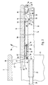
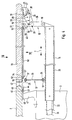
- den Tisch nach Figur 1 im Querschnitt gemäß der Schnittlinie II-II in vergrößerter Teildarstellung, aus der die unterhalb der abgeschnitten gezeigten Tischplatte angeordnete Zusatzplatte in ihrer Nichtgebrauchsstellung zusammen mit der die Zusatzplatte haltenden Beschlageinrichtung (eine zweite solche Beschlageinrichtung befindet sich oberhalb der Zeichenebene am entgegengesetzten Endbereich der Zusatzplatte) hervorgeht,
- Fig. 3
- die Anordnung nach Fig. 2 bei in die Zwischenstellung vorbewegter Zusatzplatte,
- Fig. 4
- wiederum die gleiche Anordnung wie in den Fig. 2 und 3, wobei die Zusatzplatte aus der Zwischenstellung gemäß Fig. 3 nach oben in die Gebrauchsstellung verstellt worden ist,
- Fig. 5
- einen den in Fig. 4 durch das Betätigungselement der Verriegelungseinrichtung teilweise verdeckten Schwenkarm der vorderen Schwenkarmanordnung enthaltenden Ausschnitt aus Fig. 4, wobei das Betätigungselement weggeschnitten ist,
- Fig. 6
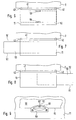
- eine schematische Draufsicht gemäß Pfeil VI in Fig. 4 auf die in der Gebrauchsstellung befindliche Zusatzplatte in verkleinerter Darstellungsweise,
- Fig. 7 und 8
- jeweils eine der Fig. 6 entsprechende Draufsicht auf die Zusatzplatte, wobei die Mausplatte zur einen bzw. zur anderen Seite hin herausgezogen ist, und
- Fig. 9
- die an der Unterseite der Zusatzplatte angeordnete Mausplatte in den Fig. 6 bis 8 entgegengesetzter Unteransicht gemäß Pfeil IX in Fig. 4 in nur den mittleren Mausplattenbereich zeigender Teildarstellung.
Um zu vermeiden, daß durch den Kabeldurchführspalt 41 ungewollt irgendwelche Gegenstände nach unten fallen, kann dem Kabeldurchführspalt 41 eine Abdeckleiste zugeordnet sein, die nach Art einer Gummilippe ausgebildet und an der Zusatzplatte 11 befestigt ist. Befindet sich die Zusatzplatte 11 in ihrer Gebrauchsstellung, deckt die Abdeckleiste den Kabeldurchführspalt 41 ab. Dabei ist die Abdeckleiste elastisch so verformbar, daß sie das Hindurchführen von Kabeln durch den Spalt 41 gestattet. Diese Variante ist ohne weiteres verständlich und daher in der Zeichnung nicht dargestellt.
Claims (20)
- Computer-Arbeitstisch mit einer Tischplatte (2) und einer an der Tisch-Vorderseite angeordneten Zusatzplatte (11) als Unterlage für eine Tastatur, wobei die Zusatzplatte (11) unterhalb der Ebene der Tischplatte (2) in Tiefenrichtung des Arbeitstisches zwischen einer unter die Tischplatte (2) zurückbewegten Nichtgebrauchsstellung und einer vor die Tischplatte (2) vorbewegten Zwischenstellung verschiebbar ist, aus der die Zusatzplatte (11) in eine in der Ebene der Tischplatte (2) vor dieser angeordnete Gebrauchsstellung nach oben hin verstellbar ist, wobei die Zusatzplatte (11) von zwei Schwenkarmanordnungen (12, 13) getragen wird, die jeweils einenends gelenkig mit der Zusatzplatte (11) und andernends gelenkig mit einer Halteeinrichtung (14) verbunden sind, wobei die Halteeinrichtung (14) in Tiefenrichtung (T) verschiebbar mit dem Korpus des Arbeitstisches (1) verbunden ist und wobei die Gelenkachsen (15, 16, 17, 18) nach Art eines Gelenkparallelogramms angeordnet sind, derart, dass die Zusatzplatte (11) mittels der Halteeinrichtung (14) zwischen der Nichtgebrauchsstellung und der Zwischenstellung verschiebbar und mittels der Schwenkarmanordnungen (12, 13) unter Beibehaltung ihrer zur Tischplatte (2) parallelen Ausrichtung zwischen der Zwischenstellung und der Gebrauchsstellung verstellbar ist, dadurch gekennzeichnet, dass von den beiden Schwenkarmanordnungen (12, 13) eine vordere Schwenkarmanordnung (12) der Tischplatte (2) abgewandt und eine hintere Schwenkarmanordnung (13) der Tischplatte (2) zugewandt ist, dass sich die beiden Schwenkarmanordnungen (12, 13) in der Nichtgebrauchsstellung, ausgehend von den sie mit den Halteeinrichtung (14) verbindenden Gelenkachsen (16, 18), nach hinten erstrecken und dass sich die beiden Schwenkarmanordnungen (12, 13) beim Überführen der Zusatzplatte (11) aus ihrer auf die Halteeinrichtung (14) geklappten Zwischenstellung in die Gebrauchsstellung aufrichten, so dass die Zusatzplatte (11) von hinten unten nach vorne oben bewegt wird.
- Computer-Arbeitstisch nach Anspruch 1, dadurch gekennzeichnet, dass mindestens eine der Schwenkarmanordnungen (13) von einer in quer zur Tiefenrichtung (T) verlaufender Längsrichtung (L) im Wesentlichen über die Länge der Zusatzplatte (11) durchgehenden und die Zusatzplatte (11) nicht nur seitlich, sondern auch im mittleren Bereich unterstützenden Stegwand (23) gebildet wird.
- Computer-Arbeitstisch nach Anspruch 1 oder 2, dadurch gekennzeichnet, dass mindestens eine der beiden Schwenkarmanordnungen (12) in ihrer der Gebrauchsstellung entsprechenden Schwenklage lösbar verriegelbar ist.
- Computer-Arbeitstisch nach Anspruch 3, dadurch gekennzeichnet, dass mindestens eine Schwenkarmanordnung (12) beim Überführen in ihre der Gebrauchsstellung entsprechende Schwenklage selbsttätig verriegelt wird.
- Computer-Arbeitstisch nach Anspruch 3 oder 4, dadurch gekennzeichnet, dass zum Entriegeln mindestens ein von der Vorderseite der Zusatzplatte (11) her zu betätigendes Betätigungselement (37) vorhanden ist.
- Computer-Arbeitstisch nach einem der Ansprüche 1 bis 5, dadurch gekennzeichnet, dass mindestes die vordere Schwenkarmanordnung (12) von zwei in Längsrichtung mit Abstand zueinander angeordneten Schwenkarmen (26) gebildet wird.
- Computer-Arbeitstisch nach Anspruch 6, dadurch gekennzeichnet, dass mindestens einer der beiden die vordere Schwenkarmanordnung (12) bildenden Schwenkarme (26) mit einem an der Zusatzplatte (11) angeordneten Verriegelungselement (27) lösbar verriegelbar ist.
- Computer-Arbeitstisch nach einem der Ansprüche 1 bis 7, dadurch gekennzeichnet, dass die Zusatzplatte (11) in ihrer Gebrauchsstellung unter Bildung eines Kabeldurchführspaltes (41) mit Abstand zur Tischplatte (2) vor dieser angeordnet ist.
- Computer-Arbeitstisch nach Anspruch 8, dadurch gekennzeichnet, dass an der in der Gebrauchsstellung der Vorderseite der Tischplatte (2) zugewandten Rückseite der Zusatzplatte (11) mindestens ein gegen die Tischplatte (2) zur Anlage gelangender Abstandshalter (42) angeordnet ist.
- Computer-Arbeitstisch nach einem der Ansprüche 1 bis 9, dadurch gekennzeichnet, dass die Zusatzplatte (11) in der Gebrauchsstellung mit der Tischplatte (2) lösbar verrastbar ist.
- Computer-Arbeitstisch nach Anspruch 10, dadurch gekennzeichnet, dass am Abstandshalter (42 ein federndes Rastglied (43) angeordnet ist, das in der Gebrauchsstellung an der Tischplatte (2) in Rasteingriff gelangt.
- Computer-Arbeitstisch nach einem der Ansprüche 1 bis 11, dadurch gekennzeichnet, dass die Zusatzplatte (11) in der Nichtgebrauchsstellung mit dem Tischkorpus lösbar verrastbar ist.
- Computer-Arbeitstisch nach Anspruch 12, dadurch gekennzeichnet, dass das am Abstandshalter (42) angeordnete Rastglied (43) in der Nichtgebrauchsstellung am Tischkorpus in Rasteingriff gelangt.
- Computer-Arbeitstisch nach einem der Ansprüche 1 bis 13, dadurch gekennzeichnet, dass an der Unterseite der Zusatzplatte (11) eine Mausplatte (50) angeordnet ist, die in eine seitlich vor die Zusatzplatte (11) vorstehende Benutzungslage überführbar ist.
- Computer-Arbeitstisch nach Anspruch 14, dadurch gekennzeichnet, dass die Mausplatte (50) in der Benutzungslage wahlweise an der einen oder der anderen Seite der Zusatzplatte (11) vorsteht.
- Computer-Arbeitstisch nach Anspruch 14 oder 15, dadurch gekennzeichnet, dass die Mausplatte (50) in quer zur Tiefenrichtung (T) verlaufender Längsrichtung (L) verschiebbar an der Zusatzplatte (11) gelagert ist.
- Computer-Arbeitstisch nach Anspruch 16, dadurch gekennzeichnet, dass der vordere Längsrandbereich (51) und/oder der hintere Längsrandbereich (52) der Mausplatte (50) von Lagerflächen (53, 54) untergriffen wird, die an an der Zusatzplatte (11) befestigten Gelenkachs-Lagerteilen (32, 56) angeordnet sind, an denen die jeweilige Schwenkarmanordnung (12, 13) gelenkig mit der Zusatzplatte (11) verbunden ist.
- Computer-Arbeitstisch nach Anspruch 17, dadurch gekennzeichnet, dass die beiden Gelenkachs-Lagerteile (56) der hinteren Schwenkarmanordnung (13) jeweils mit einem in der Gebrauchsstellung gegen die Tischplatte (2) zur Anlage gelangenden Abstandshalter (42), an dem gegebenenfalls ein Rastglied (43) angeordnet ist, fest, insbesondere einstückig, verbunden sind.
- Computer-Arbeitstisch nach einem der Ansprüche 1 bis 18, dadurch gekennzeichnet, dass die Halteeinrichtung (14) von zwei in Längsrichtung (L) mit Abstand zueinander angeordneten Haltegliedern (20) gebildet wird, die jeweils längs einer feststehend am Tischkorpus sitzenden Führungsschiene (21) verschiebbar sind.
- Computer-Arbeitstisch nach-einem der Ansprüche 8 bis 19, dadurch gekennzeichnet, dass den Kabeldurchführspalt (41) eine an der Zusatzplatte (11) angebrachte, gummilippenartige Abdeckleiste zugeordnet ist, die bei in der Gebrauchsstellung befindlicher Zusatzplatte (11) den Kabeldurchführspalt abdeckt, wobei die Abdeckleiste elastisch so verformbar ist, dass sie das Hindurchführen von Kabeln durch den Kabeldurchführspalt (41) gestattet.
Applications Claiming Priority (2)
| Application Number | Priority Date | Filing Date | Title |
|---|---|---|---|
| DE19801212A DE19801212A1 (de) | 1998-01-15 | 1998-01-15 | Computer-Arbeitstisch |
| DE19801212 | 1998-01-15 |
Publications (2)
| Publication Number | Publication Date |
|---|---|
| EP0935931A1 EP0935931A1 (de) | 1999-08-18 |
| EP0935931B1 true EP0935931B1 (de) | 2003-01-15 |
Family
ID=7854636
Family Applications (1)
| Application Number | Title | Priority Date | Filing Date |
|---|---|---|---|
| EP98123438A Expired - Lifetime EP0935931B1 (de) | 1998-01-15 | 1998-12-09 | Computer-Arbeitstisch |
Country Status (4)
| Country | Link |
|---|---|
| EP (1) | EP0935931B1 (de) |
| AT (1) | ATE230948T1 (de) |
| DE (2) | DE19801212A1 (de) |
| ES (1) | ES2186080T3 (de) |
Families Citing this family (2)
| Publication number | Priority date | Publication date | Assignee | Title |
|---|---|---|---|---|
| DE202008012195U1 (de) | 2008-09-12 | 2009-03-26 | Vogel, Olaf Reinfried | Computerarbeitstisch mit einem Flachbildschirm |
| CN220777728U (zh) * | 2023-08-30 | 2024-04-16 | 深圳缘道缘实业有限公司 | 一种键盘托架 |
Family Cites Families (4)
| Publication number | Priority date | Publication date | Assignee | Title |
|---|---|---|---|---|
| US4706919A (en) * | 1986-12-17 | 1987-11-17 | Haworth, Inc. | Keyboard support with automatic lowering mechanism |
| US4923259A (en) * | 1988-08-25 | 1990-05-08 | Microcomputer Accessories Incorporated | Adjustable keyboard drawer assembly |
| US5377951A (en) * | 1991-10-18 | 1995-01-03 | Engineered Data Products, Inc. | Adjustable computer workstation assembly and method therefore |
| WO1993025115A1 (en) * | 1992-06-05 | 1993-12-23 | Trenton Pty. Ltd. | Support means |
-
1998
- 1998-01-15 DE DE19801212A patent/DE19801212A1/de not_active Withdrawn
- 1998-12-09 ES ES98123438T patent/ES2186080T3/es not_active Expired - Lifetime
- 1998-12-09 DE DE59806930T patent/DE59806930D1/de not_active Expired - Lifetime
- 1998-12-09 EP EP98123438A patent/EP0935931B1/de not_active Expired - Lifetime
- 1998-12-09 AT AT98123438T patent/ATE230948T1/de not_active IP Right Cessation
Also Published As
| Publication number | Publication date |
|---|---|
| DE59806930D1 (de) | 2003-02-20 |
| EP0935931A1 (de) | 1999-08-18 |
| ES2186080T3 (es) | 2003-05-01 |
| ATE230948T1 (de) | 2003-02-15 |
| DE19801212A1 (de) | 1999-07-22 |
Similar Documents
| Publication | Publication Date | Title |
|---|---|---|
| EP1971243B1 (de) | Möbel mit kabelkanal | |
| DE202011000355U1 (de) | Bildschirmtragevorrichtung | |
| DE3512201C2 (de) | ||
| DE3705330A1 (de) | Tisch | |
| DE102007056832A1 (de) | Befestigungsrahmen für einen Flachbildschirm | |
| EP0033475A1 (de) | Bockleiter | |
| DE3831790C2 (de) | ||
| EP1862091A1 (de) | Arbeitsmöbel | |
| DE10307149A1 (de) | Klappbarer Fahrzeugsitz | |
| EP0198056A1 (de) | Sitzträger für stühle, insbesondere arbeitsdrehstühle. | |
| EP1258587A2 (de) | Führungseinrichtung für eine Faltschiebetür | |
| DE3636979C2 (de) | ||
| EP0350897B1 (de) | Klapptisch | |
| DE29906047U1 (de) | Auffanggerät | |
| DE102010021318B4 (de) | Beschlag | |
| EP0935931A1 (de) | Computer-Arbeitstisch | |
| EP0875173B1 (de) | Ausziehbares Bügelbrett | |
| DE3101628C2 (de) | Schreibtisch | |
| WO1990006241A1 (de) | Winkelsonnenblende für fahrzeuge | |
| DE20104209U1 (de) | Tragbarer Computer | |
| DE3315999C2 (de) | Auszieheinrichtung für einen mit einem Möbelkorpus versehenen Schrank | |
| DE102004004238B4 (de) | Klapptisch, Verwendung eines Klapptisches in Klappstellung, Stehtisch | |
| DE3007668C2 (de) | Krankentragenbühne | |
| CH686690A5 (de) | Laufwerk sowie Verschiebeeinrichtung. | |
| EP0352461B1 (de) | Schiebehebedach für Fahrzeuge |
Legal Events
| Date | Code | Title | Description |
|---|---|---|---|
| PUAI | Public reference made under article 153(3) epc to a published international application that has entered the european phase |
Free format text: ORIGINAL CODE: 0009012 |
|
| AK | Designated contracting states |
Kind code of ref document: A1 Designated state(s): AT BE CH CY DE DK ES FI FR GB GR IE IT LI LU MC NL PT SE |
|
| AX | Request for extension of the european patent |
Free format text: AL;LT;LV;MK;RO;SI |
|
| 17P | Request for examination filed |
Effective date: 19991210 |
|
| AKX | Designation fees paid |
Free format text: AT BE CH DE ES FR GB GR IT LI LU NL PT |
|
| 17Q | First examination report despatched |
Effective date: 20020318 |
|
| RAP1 | Party data changed (applicant data changed or rights of an application transferred) |
Owner name: MOLL SYSTEM- UND FUNKTIONSMOEBEL GMBH |
|
| GRAH | Despatch of communication of intention to grant a patent |
Free format text: ORIGINAL CODE: EPIDOS IGRA |
|
| GRAH | Despatch of communication of intention to grant a patent |
Free format text: ORIGINAL CODE: EPIDOS IGRA |
|
| GRAA | (expected) grant |
Free format text: ORIGINAL CODE: 0009210 |
|
| AK | Designated contracting states |
Kind code of ref document: B1 Designated state(s): AT BE CH DE ES FR GB GR IT LI LU NL PT |
|
| REG | Reference to a national code |
Ref country code: GB Ref legal event code: FG4D Free format text: NOT ENGLISH Ref country code: CH Ref legal event code: EP |
|
| REG | Reference to a national code |
Ref country code: CH Ref legal event code: NV Representative=s name: TROESCH SCHEIDEGGER WERNER AG |
|
| GBT | Gb: translation of ep patent filed (gb section 77(6)(a)/1977) |
Effective date: 20030115 |
|
| REF | Corresponds to: |
Ref document number: 59806930 Country of ref document: DE Date of ref document: 20030220 Kind code of ref document: P |
|
| REG | Reference to a national code |
Ref country code: GR Ref legal event code: EP Ref document number: 20030401137 Country of ref document: GR |
|
| REG | Reference to a national code |
Ref country code: ES Ref legal event code: FG2A Ref document number: 2186080 Country of ref document: ES Kind code of ref document: T3 |
|
| ET | Fr: translation filed | ||
| PLBE | No opposition filed within time limit |
Free format text: ORIGINAL CODE: 0009261 |
|
| STAA | Information on the status of an ep patent application or granted ep patent |
Free format text: STATUS: NO OPPOSITION FILED WITHIN TIME LIMIT |
|
| 26N | No opposition filed |
Effective date: 20031016 |
|
| PGFP | Annual fee paid to national office [announced via postgrant information from national office to epo] |
Ref country code: PT Payment date: 20041022 Year of fee payment: 7 |
|
| PG25 | Lapsed in a contracting state [announced via postgrant information from national office to epo] |
Ref country code: PT Free format text: LAPSE BECAUSE OF NON-PAYMENT OF DUE FEES Effective date: 20060609 |
|
| REG | Reference to a national code |
Ref country code: PT Ref legal event code: MM4A Effective date: 20060609 |
|
| PGFP | Annual fee paid to national office [announced via postgrant information from national office to epo] |
Ref country code: BE Payment date: 20061030 Year of fee payment: 9 |
|
| PGFP | Annual fee paid to national office [announced via postgrant information from national office to epo] |
Ref country code: LU Payment date: 20061215 Year of fee payment: 9 |
|
| PGFP | Annual fee paid to national office [announced via postgrant information from national office to epo] |
Ref country code: NL Payment date: 20071219 Year of fee payment: 10 |
|
| PGFP | Annual fee paid to national office [announced via postgrant information from national office to epo] |
Ref country code: AT Payment date: 20071212 Year of fee payment: 10 Ref country code: IT Payment date: 20071220 Year of fee payment: 10 |
|
| PGFP | Annual fee paid to national office [announced via postgrant information from national office to epo] |
Ref country code: CH Payment date: 20080303 Year of fee payment: 10 |
|
| BERE | Be: lapsed |
Owner name: *MOLL SYSTEM- UND FUNKTIONSMOBEL G.M.B.H. Effective date: 20071231 |
|
| PGFP | Annual fee paid to national office [announced via postgrant information from national office to epo] |
Ref country code: FR Payment date: 20071214 Year of fee payment: 10 |
|
| PG25 | Lapsed in a contracting state [announced via postgrant information from national office to epo] |
Ref country code: BE Free format text: LAPSE BECAUSE OF NON-PAYMENT OF DUE FEES Effective date: 20071231 |
|
| PGFP | Annual fee paid to national office [announced via postgrant information from national office to epo] |
Ref country code: ES Payment date: 20081120 Year of fee payment: 11 |
|
| PGFP | Annual fee paid to national office [announced via postgrant information from national office to epo] |
Ref country code: GR Payment date: 20081128 Year of fee payment: 11 Ref country code: GB Payment date: 20081201 Year of fee payment: 11 |
|
| REG | Reference to a national code |
Ref country code: CH Ref legal event code: PL |
|
| PG25 | Lapsed in a contracting state [announced via postgrant information from national office to epo] |
Ref country code: LU Free format text: LAPSE BECAUSE OF NON-PAYMENT OF DUE FEES Effective date: 20071209 Ref country code: AT Free format text: LAPSE BECAUSE OF NON-PAYMENT OF DUE FEES Effective date: 20081209 |
|
| NLV4 | Nl: lapsed or anulled due to non-payment of the annual fee |
Effective date: 20090701 |
|
| REG | Reference to a national code |
Ref country code: FR Ref legal event code: ST Effective date: 20090831 |
|
| PG25 | Lapsed in a contracting state [announced via postgrant information from national office to epo] |
Ref country code: LI Free format text: LAPSE BECAUSE OF NON-PAYMENT OF DUE FEES Effective date: 20081231 Ref country code: CH Free format text: LAPSE BECAUSE OF NON-PAYMENT OF DUE FEES Effective date: 20081231 |
|
| PG25 | Lapsed in a contracting state [announced via postgrant information from national office to epo] |
Ref country code: NL Free format text: LAPSE BECAUSE OF NON-PAYMENT OF DUE FEES Effective date: 20090701 |
|
| PG25 | Lapsed in a contracting state [announced via postgrant information from national office to epo] |
Ref country code: FR Free format text: LAPSE BECAUSE OF NON-PAYMENT OF DUE FEES Effective date: 20081231 |
|
| GBPC | Gb: european patent ceased through non-payment of renewal fee |
Effective date: 20091209 |
|
| PG25 | Lapsed in a contracting state [announced via postgrant information from national office to epo] |
Ref country code: GB Free format text: LAPSE BECAUSE OF NON-PAYMENT OF DUE FEES Effective date: 20091209 |
|
| REG | Reference to a national code |
Ref country code: ES Ref legal event code: FD2A Effective date: 20110330 |
|
| PGFP | Annual fee paid to national office [announced via postgrant information from national office to epo] |
Ref country code: DE Payment date: 20101109 Year of fee payment: 13 |
|
| PG25 | Lapsed in a contracting state [announced via postgrant information from national office to epo] |
Ref country code: ES Free format text: LAPSE BECAUSE OF NON-PAYMENT OF DUE FEES Effective date: 20110317 |
|
| PG25 | Lapsed in a contracting state [announced via postgrant information from national office to epo] |
Ref country code: ES Free format text: LAPSE BECAUSE OF NON-PAYMENT OF DUE FEES Effective date: 20091210 |
|
| REG | Reference to a national code |
Ref country code: DE Ref legal event code: R119 Ref document number: 59806930 Country of ref document: DE Effective date: 20120703 |
|
| PG25 | Lapsed in a contracting state [announced via postgrant information from national office to epo] |
Ref country code: DE Free format text: LAPSE BECAUSE OF NON-PAYMENT OF DUE FEES Effective date: 20120703 |
|
| PG25 | Lapsed in a contracting state [announced via postgrant information from national office to epo] |
Ref country code: IT Free format text: LAPSE BECAUSE OF NON-PAYMENT OF DUE FEES Effective date: 20081209 |