EP0933552B1 - Mechanische Einrichtung mit zwei Betriebsarten - Google Patents
Mechanische Einrichtung mit zwei Betriebsarten Download PDFInfo
- Publication number
- EP0933552B1 EP0933552B1 EP99400229A EP99400229A EP0933552B1 EP 0933552 B1 EP0933552 B1 EP 0933552B1 EP 99400229 A EP99400229 A EP 99400229A EP 99400229 A EP99400229 A EP 99400229A EP 0933552 B1 EP0933552 B1 EP 0933552B1
- Authority
- EP
- European Patent Office
- Prior art keywords
- displacement
- assembly
- control means
- relative displacement
- assemblies
- Prior art date
- Legal status (The legal status is an assumption and is not a legal conclusion. Google has not performed a legal analysis and makes no representation as to the accuracy of the status listed.)
- Expired - Lifetime
Links
Images

Classifications
-
- F—MECHANICAL ENGINEERING; LIGHTING; HEATING; WEAPONS; BLASTING
- F16—ENGINEERING ELEMENTS AND UNITS; GENERAL MEASURES FOR PRODUCING AND MAINTAINING EFFECTIVE FUNCTIONING OF MACHINES OR INSTALLATIONS; THERMAL INSULATION IN GENERAL
- F16F—SPRINGS; SHOCK-ABSORBERS; MEANS FOR DAMPING VIBRATION
- F16F7/00—Vibration-dampers; Shock-absorbers
- F16F7/08—Vibration-dampers; Shock-absorbers with friction surfaces rectilinearly movable along each other
- F16F7/09—Vibration-dampers; Shock-absorbers with friction surfaces rectilinearly movable along each other in dampers of the cylinder-and-piston type
-
- F—MECHANICAL ENGINEERING; LIGHTING; HEATING; WEAPONS; BLASTING
- F16—ENGINEERING ELEMENTS AND UNITS; GENERAL MEASURES FOR PRODUCING AND MAINTAINING EFFECTIVE FUNCTIONING OF MACHINES OR INSTALLATIONS; THERMAL INSULATION IN GENERAL
- F16F—SPRINGS; SHOCK-ABSORBERS; MEANS FOR DAMPING VIBRATION
- F16F9/00—Springs, vibration-dampers, shock-absorbers, or similarly-constructed movement-dampers using a fluid or the equivalent as damping medium
- F16F9/32—Details
- F16F9/50—Special means providing automatic damping adjustment, i.e. self-adjustment of damping by particular sliding movements of a valve element, other than flexions or displacement of valve discs; Special means providing self-adjustment of spring characteristics
- F16F9/504—Inertia, i.e. acceleration,-sensitive means
Definitions
- the present invention relates to the field of systems mechanical movement control.
- a device according to the invention makes it possible to control a rapidly accelerated movement which could cause an operational or safety problem.
- this device can be used in high impulse projectile launchers, in front present two different depreciation dynamics.
- a such a damping device comprises a fixed part, a part mobile and friction means interposed between the fixed part and the part mobile.
- the aim of the invention is to improve the dynamics of depreciation. This goal is achieved by a mechanical device, having two relative modes of movement from one set to another, the transition between these two modes being controlled and determined by the temporal profile of the relative displacement.
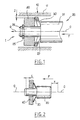
- FIG. 1 a diagram which we will make reference to describe the mechanical device 1 according to the invention. Are represented in this diagram, a fixed assembly 10, a mobile assembly 20, elastic control means 30 and an inertial mass 40.
- the fixed assembly 10 comprises, for example, a fixed hollow cylinder 11 of revolution.
- the mobile assembly 20 comprises a mobile cylinder 21 of revolution, full, with an external diameter less than the internal diameter of the fixed cylinder 11, so as to allow free axial movement along O-O, within this one.
- This movable cylinder 21 is provided with a narrowed portion 26, in diameter, also cylindrical and coaxial.
- the narrowed portion 26 is limited from the side opposite its free end by a stop 27.
- Means of elastic control 30 and the inertial mass 40 are threaded on the part narrowed 26.
- the elastic control means 30 are interposed between the mass 40 and the stop 27.
- These elastic control means 30 and the mass 40 are maintained on the narrowed part 26 of the mobile assembly 20 by a fixing element 25.
- this fixing element 25 is a clip or a split washer.
- the inertial mass 40 is a hollow cylinder of revolution, of external diameter smaller than the internal diameter of the cylinder 11 of the assembly fixed 10, so as to allow free axial movement, inside this one.
- This inertial mass 40 is carried by the mobile assembly 20, its internal diameter being slightly greater than the external diameter of the narrowed portion 26 of the movable cylinder 21, so as to allow a free axial movement thereon.
- Elastic control means 30 are here a washer elastic, for example of the Siam-Ringspann type.
- a set J is provided, at rest, between the elastic control means 30 and the fixed assembly 10.
- the displacement of the mobile assembly 1 is transmitted to ground 40 without the elastic control means 30 being deformed enough to eliminate the clearance J.
- the cylinder 21 of the movable assembly 20 then moves freely, inside the cylinder 11 of the fixed assembly 10.
- the device according to the invention remains in a first mode of relative displacement.
- the elastic control means 30 are designed to brace itself, the friction force increases rapidly and continuously, up to a limit value, when the relative displacement of the two sets increases. Beyond this limit value, the forces of friction are strong enough to block relative movement.
- the elastic control means can also be designed to yield above a predetermined threshold force, beyond of which the device comprising the mechanical device 1 is likely to be damaged. They then act as a means of safety, in case of excessive effort. This means of security can also be studied so that having yielded once to excessive effort, a new use of device comprising the mechanical device 1, according to the invention, either prohibited as is.
- the mechanical device allows a transition essentially between a mode of free movement or a mode of movement depreciated or at the blocked limit.
- This transition depends on the dynamics of the inertial mass 40, elastic control means 30.
- the adjustment of this dynamic provides a transition between the two modes of travel relative, for desired displacement time profiles.
- Figure 2 supports the description of the modeling of the dynamics of the mechanical device 1 according to the invention. Under the effect of a impulse, the mobile assembly moves by a distance x in the direction F with respect to the fixed assembly 10 and by a distance ⁇ from the mass inertial 40.
- the displacement transition takes place at time T 1 after the initial instant of the pulse (fig. 3). There is a first mode of displacement before T 1 , during a phase 1, during which the mobile assembly 20 is accelerated and a second mode of displacement after T 1 , which corresponds to a second phase of displacement, during which the movement of the mobile assembly 20 is damped, at constant speed.
- the play J predictable for proper operation will be of the order of 0.05 mm.
- the geometry of the elastic means 30 then makes it possible to choose the game J. We could, for example, use Siam-Ringspann washers standard (ref. A 10 SS 20).
- the mechanical device 1 according to the invention can be improved by to various variants. Some of these variants are presented below, but they are in no way limiting.
- a mechanical device 1 has already been described above, damping the relative displacement of the two assemblies 10, 20 thanks to the buckling of the elastic control means 30.
- the device according to the invention can include different types of damping means designed to dampen the relative displacement of the two sets 10 and 20.
- the means shock absorbers can advantageously be constituted by means of elastic control 30, comprising at least one washer working at buckling, supplemented by friction means 60 conforming to those described in French patent application FR 2 697 881.
- the mechanical device 1, according to the invention may include blocking means designed to block the relative displacement of the two assemblies 10, 20 if the friction forces friction means on the fixed assembly 10 increase beyond a limit value.
- These blocking means can then comprise at least a rigid washer in the radial direction, working in bracing. The latter may or may not yield and release the relative displacement if the effort imposing this displacement is greater than a predetermined threshold.
- a mechanical device 1 may have elastic control means 30 which include at minus an elastic washer interposed between the movable assembly 20 and the inertial mass 40.
- the elastic control means 30 may also include a spring, for example helical, interposed between a washer or a set of washers and the stopper 27 of the mobile assembly 20.
- the mechanical device 1, according to the invention, can also have its inertial mass 40 placed on an intermediate piece 22, associated with the mobile assembly 20 and mobile on said intermediate piece 22.
- This variant of the mechanical device 1 is shown in FIG. 5.
- the part intermediate 22 includes for example a ring 23, circumferential to the narrowed part 26 of the mobile assembly 20, but with sufficient play to be mobile on it.
- On the ring 23 extends radially a shoulder 24, located on the edge of the ring 23, opposite the free end of the mobile assembly 20 engaged in the fixed assembly 10.
- This shoulder can take a continuous circular shape or include several elements projecting from the ring 23 and distributed around it.
- the shoulder 24 has an external circumferential size less than the internal diameter of the cylinder 11 of the fixed assembly 10, so that the intermediate piece 22 is free to move in translation along the axis O-O, with respect to the fixed assembly 10.
- the inertial mass 40 is then placed around the ring 23, so as to be free in translation along the axis O-O on the ring 23.
- elastic control means 30 between the moving mass 40 and the shoulder 24 and spring means 50 between the part intermediate 22 and the stop 27 limiting the narrowed part 26 on the opposite side at the free end of the mobile assembly 20, engaged in the cylinder 11.
- the elastic control means 30 can be formed of a single elastic washer and the spring means 50 of a set elastic washers liable to buckle.
- the displacement dynamics is linked to a single washer, which is placed between the moving mass 40 and the shoulder 24, while the axial force of spring is transmitted to all the other washers, located between the part intermediate 22 and the stopper 27.
- the single elastic washer constituting the elastic control means 30 may have a stiffness constant weaker than each washer, the whole of which constitutes the means of spring 50.
- the single elastic washer more easily undergoes a deformation under the effect of the impulse.
- said single elastic washer rubs against the inner wall of the cylinder fixed 11, reinforcing the inertia effect.
- the set of elastic washers of spring means 50 is then stressed.
- the washers of this set crash; their outer circumferential end comes into contact with the inner wall of cylinder 11; they blaze; and this results in friction dampening the pulse.
- the stiffness of the washers constituting this assembly can be chosen high in order to maximize the friction forces. So the stiffness of the elastic washer of the elastic control means 30 is chosen to optimize the triggering of the transition between the two relative modes of movement between the fixed assembly 10 and the mobile assembly 20, while the stiffness of the washers of the spring means 50 is chosen to optimize the damping of said relative displacement.
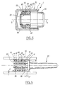
- the mechanical device 1 may include means for friction, between the fixed assembly 10 and the mobile assembly 20 (FIG. 6).
- a shoe 60 can be placed between the cylinder 11 of the fixed assembly 10 and the elastic control means 30.
- the shoe 60 may be a socket of revolution, split longitudinally, of lower external diameter of the radial clearance J, to the internal diameter of the cylinder 11.
- Each transverse edge of the shoe 60 includes a shoulder 61, which extends radially from the shoe 60 towards the narrowed part 26.
- spring means 50 are made of elastic washers 51 of external diameter at rest approximately equal to or slightly less than the internal diameter of the pad 60.
- the internal diameter of these washers 51 is slightly greater to that of the narrowed portion 26.
- the shoe assembly 60 - spring means 50 may have a mass adapted to constitute at the same time the inertial mass 40.
- the elastic control means 30, here consisting of a spring spiral, are located between the movable assembly 20 and the spring means 50.
- devices according to the invention can be designed in such a way that the friction takes place on a part of the mobile assembly.
- the cylinder 21 is fixed and that it is the cylinder 11 which is mobile.
- a device according to the invention can be placed in series or in parallel with at least one shock absorber or a blocking of any kind. This allows to obtain transitions between cushioned displacement and free displacement, and conversely, between two damped displacements of characteristics different, or a transition from a damped displacement to a blockage and vice versa, or even a transition between blocked state and free movement or vice versa.
Landscapes
- Engineering & Computer Science (AREA)
- General Engineering & Computer Science (AREA)
- Mechanical Engineering (AREA)
- Vibration Prevention Devices (AREA)
- Vibration Dampers (AREA)
Claims (15)
- Mechanische Vorrichtung (1) zum Steuern des Übergangs zwischen zwei Betriebsarten der relativen Versetzung zwischen zwei Gegenständen, mit den folgenden Merkmalen:dadurch gekennzeichnet, daß sie außerdem die folgenden Merkmale aufweist:zwei Anordnungen (10, 20), die zur relativen, geführten Translation befähigt sind, von denen die eine fest (10), die andere beweglich (20) genannt ist,elastische Steuermittel (30), die mit einem Steuerspiel J zwischen den beiden Anordnungen (10, 20) eingefügt sind, um die Art der relativen Versetzung zu definieren, undeine träge Masse (40), die einer der Anordnungen (20) zugeordnet ist und dazu eingerichtet ist, auf die Steuermittel (30) selektiv in Funktion des zeitlichen Profils der Versetzung der beweglichen Anordnung (20) einzuwirken, um das Spiel und die Art der relativen Versetzung zu ändern.
- Vorrichtung nach Anspruch 1, dadurch gekennzeichnet, daß die elastischen Steuermittel (30) so bemessen sind, daß sie umknickend arbeiten.
- Vorrichtung nach irgendeinem der Ansprüche 1 oder 2, dadurch gekennzeichnet, daß sie Dämpfungsmittel aufweist, die dazu konzipiert sind, die relative Versetzung der beiden Anordnungen (10, 20) zu dämpfen.
- Vorrichtung nach Anspruch 3, dadurch gekennzeichnet, daß die Dämpfungsmittel mindestens eine Scheibe aufweisen, die beim Umknicken wirksam wird.
- Vorrichtung nach einem der vorangehenden Ansprüche, dadurch gekennzeichnet, daß sie Reibungsmittel (60) zwischen der festen Anordnung (10) und der beweglichen Anordnung (20) aufweist.
- Vorrichtung nach einem der vorangehenden Ansprüche, dadurch gekennzeichnet, daß sie außerdem Mittel zum Sperren der relativen Versetzung der beiden Anordnungen (10, 20) aufweist, wenn die Reibungskraft über einen Grenzwert hinaus zunimmt.
- Vorrichtung nach Anspruch 6, dadurch gekennzeichnet, daß die Mittel zum Sperren mindestens eine Scheibe aufweisen, die in radialer Richtung steif ist und verspreizend arbeitet.
- Vorrichtung nach Anspruch 7, dadurch gekennzeichnet, daß die in radialer Richtung steife Scheibe dazu konzipiert ist, nachzugeben und die relative Versetzung freizugeben, wenn die Kraft, die diese Versetzung hervorruft, größer ist als ein bestimmter Schwellenwert.
- Vorrichtung nach irgendeinem der vorangehenden Ansprüche, dadurch gekennzeichnet, daß die elastischen Steuermittel mindestens eine elastische Scheibe (30) aufweisen, die zwischen der beweglichen Anordnung (20) und der trägen Masse (40) eingesetzt ist.
- Vorrichtung nach irgendeinem der vorangehenden Ansprüche, dadurch gekennzeichnet, daß die träge Masse auf einem Zwischenstück (22) angeordnet ist, das der beweglichen Anordnung (20) zugeordnet ist.
- Vorrichtung nach Anspruch 9, dadurch gekennzeichnet, daß Federmittel (50) zwischen dem Zwischenstück (22) und der beweglichen Anordnung (20) angeordnet sind.
- Vorrichtung nach irgendeinem der vorangehenden Ansprüche, dadurch gekennzeichnet, daß mindestens ein Reibungsklotz (60) zwischen dem Zylinder (11) der festen Anordnung (10) und den elastischen Steuermitteln (30) angeordnet sind.
- Verwendung der Vorrichtung nach irgendeinem der vorangehenden Ansprüche in mechanischen Systemen zum Steuern einer beschleunigten Versetzung.
- Verwendung der Vorrichtung nach irgendeinem der vorangehenden Ansprüche in Abschußeinrichtungen für Projektile mit hoher Wucht.
- Mechanisches System zum Steuern von Versetzung, dadurch gekennzeichnet, daß es eine Vorrichtung nach irgendeinem der vorangehenden Ansprüche aufweist, die parallel oder in Reihe mit mindestens einem Dämpfer oder mit Mitteln zum Sperren irgendeiner beliebigen Art angeordnet ist.
Applications Claiming Priority (2)
| Application Number | Priority Date | Filing Date | Title |
|---|---|---|---|
| FR9801149A FR2774444B1 (fr) | 1998-02-02 | 1998-02-02 | Dispositif mecanique a deplacement bimodal |
| FR9801149 | 1998-02-02 |
Publications (2)
| Publication Number | Publication Date |
|---|---|
| EP0933552A1 EP0933552A1 (de) | 1999-08-04 |
| EP0933552B1 true EP0933552B1 (de) | 2003-05-21 |
Family
ID=9522457
Family Applications (1)
| Application Number | Title | Priority Date | Filing Date |
|---|---|---|---|
| EP99400229A Expired - Lifetime EP0933552B1 (de) | 1998-02-02 | 1999-02-02 | Mechanische Einrichtung mit zwei Betriebsarten |
Country Status (6)
| Country | Link |
|---|---|
| US (1) | US6364074B2 (de) |
| EP (1) | EP0933552B1 (de) |
| CA (1) | CA2261360A1 (de) |
| DE (1) | DE69907983T2 (de) |
| ES (1) | ES2198857T3 (de) |
| FR (1) | FR2774444B1 (de) |
Families Citing this family (8)
| Publication number | Priority date | Publication date | Assignee | Title |
|---|---|---|---|---|
| US6672575B2 (en) * | 2001-06-12 | 2004-01-06 | Lord Corporation | Surface effect damper |
| US20030168295A1 (en) * | 2002-02-12 | 2003-09-11 | Zhixiu Han | Active vibration isolation system |
| FR2869662B1 (fr) * | 2004-04-30 | 2006-06-23 | Lacroix Soc E | Dispositif amortisseur a friction adaptable |
| FR2869663B1 (fr) * | 2004-04-30 | 2006-06-23 | Lacroix Soc E | Dispositif amortisseur a friction |
| WO2007031611A1 (fr) * | 2005-09-15 | 2007-03-22 | Etienne Lacroix Tous Artifices S.A. | Dispositif amortisseur a friction adaptable |
| US20070246785A1 (en) * | 2006-04-20 | 2007-10-25 | Asml Netherlands B.V. | Locking device, adjustment mechanism and lithographic apparatus |
| DE102016210790A1 (de) * | 2016-06-16 | 2017-12-21 | Zf Friedrichshafen Ag | Dämpfventileinrichtung mit progressiver Dämpfkraftkennlinie |
| DE102019215558A1 (de) * | 2019-10-10 | 2021-04-15 | Zf Friedrichshafen Ag | Drosselstelle für einen Schwingungsdämpfer |
Family Cites Families (10)
| Publication number | Priority date | Publication date | Assignee | Title |
|---|---|---|---|---|
| US2539275A (en) * | 1945-09-22 | 1951-01-23 | Bofors Ab | Forward damper device for firearms with a recoil mantle |
| US2459537A (en) * | 1946-05-27 | 1949-01-18 | Peter B Oberstadt | Dampening devices for shock absorbers and the like |
| FR1122015A (fr) * | 1955-02-01 | 1956-08-30 | Amortisseur à friction | |
| BE548536A (de) * | 1956-06-11 | |||
| FR2127224A5 (de) * | 1971-03-01 | 1972-10-13 | Int Vibration Engin | |
| DE2240943A1 (de) * | 1972-08-19 | 1974-02-28 | Adalbert Freyler | Stoss- und schwingungsdaempfer in teleskopform, insbesondere fuer kraftfahrzeuge |
| FR2333165A1 (fr) * | 1975-11-26 | 1977-06-24 | Quillery | Dispositif d'amortissement, en particulier pour pare-chocs de vehicule |
| SU868183A1 (ru) * | 1980-01-14 | 1981-09-30 | Предприятие П/Я Р-6896 | Демпфер сухого трени |
| DE4018599A1 (de) * | 1989-07-10 | 1991-01-24 | Miele & Cie | Reibungsdaempfer, insbesondere fuer trommelwaschmaschinen |
| FR2697881B1 (fr) * | 1992-11-06 | 1995-01-27 | Lacroix E Tous Artifices | Dispositif amortisseur pour système mécanique. |
-
1998
- 1998-02-02 FR FR9801149A patent/FR2774444B1/fr not_active Expired - Fee Related
-
1999
- 1999-02-01 US US09/241,971 patent/US6364074B2/en not_active Expired - Fee Related
- 1999-02-01 CA CA002261360A patent/CA2261360A1/fr not_active Abandoned
- 1999-02-02 EP EP99400229A patent/EP0933552B1/de not_active Expired - Lifetime
- 1999-02-02 ES ES99400229T patent/ES2198857T3/es not_active Expired - Lifetime
- 1999-02-02 DE DE69907983T patent/DE69907983T2/de not_active Expired - Fee Related
Also Published As
| Publication number | Publication date |
|---|---|
| FR2774444A1 (fr) | 1999-08-06 |
| US20020000351A1 (en) | 2002-01-03 |
| FR2774444B1 (fr) | 2000-05-19 |
| DE69907983D1 (de) | 2003-06-26 |
| EP0933552A1 (de) | 1999-08-04 |
| US6364074B2 (en) | 2002-04-02 |
| DE69907983T2 (de) | 2004-02-19 |
| ES2198857T3 (es) | 2004-02-01 |
| CA2261360A1 (fr) | 1999-08-02 |
Similar Documents
| Publication | Publication Date | Title |
|---|---|---|
| EP2607743B1 (de) | Dämpfer mit reibungsdampfungsmitteln | |
| EP3190310B1 (de) | Pendel-dämpfungsvorrichtung | |
| CA2956917C (fr) | Atterrisseur pour aeronef comportant un amortisseur principal et un amortisseur secondaire anti shimmy | |
| FR2680212A1 (fr) | Disque d'embrayage pour un embrayage a friction d'un vehicule automobile. | |
| FR2511456A1 (fr) | Dispositif de transmission du couple de rotation, notamment pour disque d'embrayage | |
| FR2767888A1 (fr) | Amortisseur d'oscillation de torsion | |
| EP0933552B1 (de) | Mechanische Einrichtung mit zwei Betriebsarten | |
| WO2015140456A1 (fr) | Dispositif d'amortissement pour chaine de propulsion de vehicule | |
| FR2771466A1 (fr) | Amortisseur d'oscillations de rotation | |
| EP3190045B1 (de) | Fahrwerk für ein luftfahrzeug, das mit einem sekundären anti-shimmy-dämpfer ausgestattet ist | |
| WO2017072338A1 (fr) | Absorbeur de vibration | |
| FR3014519A1 (fr) | Dispositif d'amortissement de torsion a pendule d'efficacite de filtration amelioree | |
| FR2769676A1 (fr) | Amortisseur d'oscillations de torsion | |
| FR3039872A1 (fr) | Organe de roulement pour dispositif d'amortissement d'oscillations de torsion | |
| FR3051869A1 (fr) | Dispositif de transmission de couple, notamment pour vehicule automobile | |
| FR2809150A1 (fr) | Amortisseur d'oscilations de torsion | |
| WO2019115479A1 (fr) | Organe de roulement pour dispositif d'amortissement pendulaire | |
| WO2019110310A1 (fr) | Dispositif d'amortissement pendulaire centrifuge | |
| CA2563794A1 (fr) | Systeme amortisseur a detente rapide et butee hydraulique de fin de course et procede d'utilisation | |
| EP3199830B1 (de) | Pendel-dämpfungsvorrichtung | |
| FR3067430A1 (fr) | Dispositif d'amortissement pendulaire | |
| FR3046647A1 (fr) | Dispositif d'amortissement pendulaire | |
| FR3052520A1 (fr) | Procede de realisation d'un dispositif d'amortissement pendulaire | |
| EP1978277B1 (de) | Ausgleichsmodul für einen Fahrzeughydraulikdämpfer und Dämpfer, der mit einem solchen Ausgleichsmodul ausgestattet ist | |
| FR3048271A1 (fr) | Dispositif d'amortissement pendulaire |
Legal Events
| Date | Code | Title | Description |
|---|---|---|---|
| PUAI | Public reference made under article 153(3) epc to a published international application that has entered the european phase |
Free format text: ORIGINAL CODE: 0009012 |
|
| AK | Designated contracting states |
Kind code of ref document: A1 Designated state(s): BE DE ES FR GB SE |
|
| AX | Request for extension of the european patent |
Free format text: AL;LT;LV;MK;RO;SI |
|
| RTI1 | Title (correction) |
Free format text: MECHANICAL DEVICE HAVING TWO MODES OF OPERATION |
|
| 17P | Request for examination filed |
Effective date: 20000124 |
|
| AKX | Designation fees paid |
Free format text: BE DE ES FR GB SE |
|
| GRAH | Despatch of communication of intention to grant a patent |
Free format text: ORIGINAL CODE: EPIDOS IGRA |
|
| GRAH | Despatch of communication of intention to grant a patent |
Free format text: ORIGINAL CODE: EPIDOS IGRA |
|
| GRAA | (expected) grant |
Free format text: ORIGINAL CODE: 0009210 |
|
| AK | Designated contracting states |
Designated state(s): BE DE ES FR GB SE |
|
| REG | Reference to a national code |
Ref country code: GB Ref legal event code: FG4D Free format text: NOT ENGLISH |
|
| REF | Corresponds to: |
Ref document number: 69907983 Country of ref document: DE Date of ref document: 20030626 Kind code of ref document: P |
|
| REG | Reference to a national code |
Ref country code: SE Ref legal event code: TRGR |
|
| GBT | Gb: translation of ep patent filed (gb section 77(6)(a)/1977) |
Effective date: 20030730 |
|
| REG | Reference to a national code |
Ref country code: ES Ref legal event code: FG2A Ref document number: 2198857 Country of ref document: ES Kind code of ref document: T3 |
|
| PLBE | No opposition filed within time limit |
Free format text: ORIGINAL CODE: 0009261 |
|
| STAA | Information on the status of an ep patent application or granted ep patent |
Free format text: STATUS: NO OPPOSITION FILED WITHIN TIME LIMIT |
|
| 26N | No opposition filed |
Effective date: 20040224 |
|
| PGFP | Annual fee paid to national office [announced via postgrant information from national office to epo] |
Ref country code: SE Payment date: 20070118 Year of fee payment: 9 |
|
| PGFP | Annual fee paid to national office [announced via postgrant information from national office to epo] |
Ref country code: GB Payment date: 20070209 Year of fee payment: 9 Ref country code: DE Payment date: 20070209 Year of fee payment: 9 |
|
| PGFP | Annual fee paid to national office [announced via postgrant information from national office to epo] |
Ref country code: ES Payment date: 20070215 Year of fee payment: 9 |
|
| PGFP | Annual fee paid to national office [announced via postgrant information from national office to epo] |
Ref country code: BE Payment date: 20070228 Year of fee payment: 9 |
|
| PGFP | Annual fee paid to national office [announced via postgrant information from national office to epo] |
Ref country code: FR Payment date: 20070228 Year of fee payment: 9 |
|
| BERE | Be: lapsed |
Owner name: S.A. ETIENNE *LACROIX - TOUS ARTIFICES Effective date: 20080228 |
|
| EUG | Se: european patent has lapsed | ||
| GBPC | Gb: european patent ceased through non-payment of renewal fee |
Effective date: 20080202 |
|
| REG | Reference to a national code |
Ref country code: FR Ref legal event code: ST Effective date: 20081031 |
|
| PG25 | Lapsed in a contracting state [announced via postgrant information from national office to epo] |
Ref country code: SE Free format text: LAPSE BECAUSE OF NON-PAYMENT OF DUE FEES Effective date: 20080203 Ref country code: DE Free format text: LAPSE BECAUSE OF NON-PAYMENT OF DUE FEES Effective date: 20080902 |
|
| PG25 | Lapsed in a contracting state [announced via postgrant information from national office to epo] |
Ref country code: BE Free format text: LAPSE BECAUSE OF NON-PAYMENT OF DUE FEES Effective date: 20080228 |
|
| PG25 | Lapsed in a contracting state [announced via postgrant information from national office to epo] |
Ref country code: FR Free format text: LAPSE BECAUSE OF NON-PAYMENT OF DUE FEES Effective date: 20080229 |
|
| REG | Reference to a national code |
Ref country code: ES Ref legal event code: FD2A Effective date: 20080204 |
|
| PG25 | Lapsed in a contracting state [announced via postgrant information from national office to epo] |
Ref country code: GB Free format text: LAPSE BECAUSE OF NON-PAYMENT OF DUE FEES Effective date: 20080202 |
|
| PG25 | Lapsed in a contracting state [announced via postgrant information from national office to epo] |
Ref country code: ES Free format text: LAPSE BECAUSE OF NON-PAYMENT OF DUE FEES Effective date: 20080204 |