EP0933552B1 - Mechanical device having two modes of operation - Google Patents
Mechanical device having two modes of operation Download PDFInfo
- Publication number
- EP0933552B1 EP0933552B1 EP99400229A EP99400229A EP0933552B1 EP 0933552 B1 EP0933552 B1 EP 0933552B1 EP 99400229 A EP99400229 A EP 99400229A EP 99400229 A EP99400229 A EP 99400229A EP 0933552 B1 EP0933552 B1 EP 0933552B1
- Authority
- EP
- European Patent Office
- Prior art keywords
- displacement
- assembly
- control means
- relative displacement
- assemblies
- Prior art date
- Legal status (The legal status is an assumption and is not a legal conclusion. Google has not performed a legal analysis and makes no representation as to the accuracy of the status listed.)
- Expired - Lifetime
Links
Images

Classifications
-
- F—MECHANICAL ENGINEERING; LIGHTING; HEATING; WEAPONS; BLASTING
- F16—ENGINEERING ELEMENTS AND UNITS; GENERAL MEASURES FOR PRODUCING AND MAINTAINING EFFECTIVE FUNCTIONING OF MACHINES OR INSTALLATIONS; THERMAL INSULATION IN GENERAL
- F16F—SPRINGS; SHOCK-ABSORBERS; MEANS FOR DAMPING VIBRATION
- F16F7/00—Vibration-dampers; Shock-absorbers
- F16F7/08—Vibration-dampers; Shock-absorbers with friction surfaces rectilinearly movable along each other
- F16F7/09—Vibration-dampers; Shock-absorbers with friction surfaces rectilinearly movable along each other in dampers of the cylinder-and-piston type
-
- F—MECHANICAL ENGINEERING; LIGHTING; HEATING; WEAPONS; BLASTING
- F16—ENGINEERING ELEMENTS AND UNITS; GENERAL MEASURES FOR PRODUCING AND MAINTAINING EFFECTIVE FUNCTIONING OF MACHINES OR INSTALLATIONS; THERMAL INSULATION IN GENERAL
- F16F—SPRINGS; SHOCK-ABSORBERS; MEANS FOR DAMPING VIBRATION
- F16F9/00—Springs, vibration-dampers, shock-absorbers, or similarly-constructed movement-dampers using a fluid or the equivalent as damping medium
- F16F9/32—Details
- F16F9/50—Special means providing automatic damping adjustment, i.e. self-adjustment of damping by particular sliding movements of a valve element, other than flexions or displacement of valve discs; Special means providing self-adjustment of spring characteristics
- F16F9/504—Inertia, i.e. acceleration,-sensitive means
Definitions
- the present invention relates to the field of systems mechanical movement control.
- a device according to the invention makes it possible to control a rapidly accelerated movement which could cause an operational or safety problem.
- this device can be used in high impulse projectile launchers, in front present two different depreciation dynamics.
- a such a damping device comprises a fixed part, a part mobile and friction means interposed between the fixed part and the part mobile.
- the aim of the invention is to improve the dynamics of depreciation. This goal is achieved by a mechanical device, having two relative modes of movement from one set to another, the transition between these two modes being controlled and determined by the temporal profile of the relative displacement.
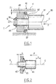
- FIG. 1 a diagram which we will make reference to describe the mechanical device 1 according to the invention. Are represented in this diagram, a fixed assembly 10, a mobile assembly 20, elastic control means 30 and an inertial mass 40.
- the fixed assembly 10 comprises, for example, a fixed hollow cylinder 11 of revolution.
- the mobile assembly 20 comprises a mobile cylinder 21 of revolution, full, with an external diameter less than the internal diameter of the fixed cylinder 11, so as to allow free axial movement along O-O, within this one.
- This movable cylinder 21 is provided with a narrowed portion 26, in diameter, also cylindrical and coaxial.
- the narrowed portion 26 is limited from the side opposite its free end by a stop 27.
- Means of elastic control 30 and the inertial mass 40 are threaded on the part narrowed 26.
- the elastic control means 30 are interposed between the mass 40 and the stop 27.
- These elastic control means 30 and the mass 40 are maintained on the narrowed part 26 of the mobile assembly 20 by a fixing element 25.
- this fixing element 25 is a clip or a split washer.
- the inertial mass 40 is a hollow cylinder of revolution, of external diameter smaller than the internal diameter of the cylinder 11 of the assembly fixed 10, so as to allow free axial movement, inside this one.
- This inertial mass 40 is carried by the mobile assembly 20, its internal diameter being slightly greater than the external diameter of the narrowed portion 26 of the movable cylinder 21, so as to allow a free axial movement thereon.
- Elastic control means 30 are here a washer elastic, for example of the Siam-Ringspann type.
- a set J is provided, at rest, between the elastic control means 30 and the fixed assembly 10.
- the displacement of the mobile assembly 1 is transmitted to ground 40 without the elastic control means 30 being deformed enough to eliminate the clearance J.
- the cylinder 21 of the movable assembly 20 then moves freely, inside the cylinder 11 of the fixed assembly 10.
- the device according to the invention remains in a first mode of relative displacement.
- the elastic control means 30 are designed to brace itself, the friction force increases rapidly and continuously, up to a limit value, when the relative displacement of the two sets increases. Beyond this limit value, the forces of friction are strong enough to block relative movement.
- the elastic control means can also be designed to yield above a predetermined threshold force, beyond of which the device comprising the mechanical device 1 is likely to be damaged. They then act as a means of safety, in case of excessive effort. This means of security can also be studied so that having yielded once to excessive effort, a new use of device comprising the mechanical device 1, according to the invention, either prohibited as is.
- the mechanical device allows a transition essentially between a mode of free movement or a mode of movement depreciated or at the blocked limit.
- This transition depends on the dynamics of the inertial mass 40, elastic control means 30.
- the adjustment of this dynamic provides a transition between the two modes of travel relative, for desired displacement time profiles.
- Figure 2 supports the description of the modeling of the dynamics of the mechanical device 1 according to the invention. Under the effect of a impulse, the mobile assembly moves by a distance x in the direction F with respect to the fixed assembly 10 and by a distance ⁇ from the mass inertial 40.
- the displacement transition takes place at time T 1 after the initial instant of the pulse (fig. 3). There is a first mode of displacement before T 1 , during a phase 1, during which the mobile assembly 20 is accelerated and a second mode of displacement after T 1 , which corresponds to a second phase of displacement, during which the movement of the mobile assembly 20 is damped, at constant speed.
- the play J predictable for proper operation will be of the order of 0.05 mm.
- the geometry of the elastic means 30 then makes it possible to choose the game J. We could, for example, use Siam-Ringspann washers standard (ref. A 10 SS 20).
- the mechanical device 1 according to the invention can be improved by to various variants. Some of these variants are presented below, but they are in no way limiting.
- a mechanical device 1 has already been described above, damping the relative displacement of the two assemblies 10, 20 thanks to the buckling of the elastic control means 30.
- the device according to the invention can include different types of damping means designed to dampen the relative displacement of the two sets 10 and 20.
- the means shock absorbers can advantageously be constituted by means of elastic control 30, comprising at least one washer working at buckling, supplemented by friction means 60 conforming to those described in French patent application FR 2 697 881.
- the mechanical device 1, according to the invention may include blocking means designed to block the relative displacement of the two assemblies 10, 20 if the friction forces friction means on the fixed assembly 10 increase beyond a limit value.
- These blocking means can then comprise at least a rigid washer in the radial direction, working in bracing. The latter may or may not yield and release the relative displacement if the effort imposing this displacement is greater than a predetermined threshold.
- a mechanical device 1 may have elastic control means 30 which include at minus an elastic washer interposed between the movable assembly 20 and the inertial mass 40.
- the elastic control means 30 may also include a spring, for example helical, interposed between a washer or a set of washers and the stopper 27 of the mobile assembly 20.
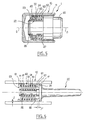
- the mechanical device 1, according to the invention, can also have its inertial mass 40 placed on an intermediate piece 22, associated with the mobile assembly 20 and mobile on said intermediate piece 22.
- This variant of the mechanical device 1 is shown in FIG. 5.
- the part intermediate 22 includes for example a ring 23, circumferential to the narrowed part 26 of the mobile assembly 20, but with sufficient play to be mobile on it.
- On the ring 23 extends radially a shoulder 24, located on the edge of the ring 23, opposite the free end of the mobile assembly 20 engaged in the fixed assembly 10.
- This shoulder can take a continuous circular shape or include several elements projecting from the ring 23 and distributed around it.
- the shoulder 24 has an external circumferential size less than the internal diameter of the cylinder 11 of the fixed assembly 10, so that the intermediate piece 22 is free to move in translation along the axis O-O, with respect to the fixed assembly 10.
- the inertial mass 40 is then placed around the ring 23, so as to be free in translation along the axis O-O on the ring 23.
- elastic control means 30 between the moving mass 40 and the shoulder 24 and spring means 50 between the part intermediate 22 and the stop 27 limiting the narrowed part 26 on the opposite side at the free end of the mobile assembly 20, engaged in the cylinder 11.
- the elastic control means 30 can be formed of a single elastic washer and the spring means 50 of a set elastic washers liable to buckle.
- the displacement dynamics is linked to a single washer, which is placed between the moving mass 40 and the shoulder 24, while the axial force of spring is transmitted to all the other washers, located between the part intermediate 22 and the stopper 27.
- the single elastic washer constituting the elastic control means 30 may have a stiffness constant weaker than each washer, the whole of which constitutes the means of spring 50.
- the single elastic washer more easily undergoes a deformation under the effect of the impulse.
- said single elastic washer rubs against the inner wall of the cylinder fixed 11, reinforcing the inertia effect.
- the set of elastic washers of spring means 50 is then stressed.
- the washers of this set crash; their outer circumferential end comes into contact with the inner wall of cylinder 11; they blaze; and this results in friction dampening the pulse.
- the stiffness of the washers constituting this assembly can be chosen high in order to maximize the friction forces. So the stiffness of the elastic washer of the elastic control means 30 is chosen to optimize the triggering of the transition between the two relative modes of movement between the fixed assembly 10 and the mobile assembly 20, while the stiffness of the washers of the spring means 50 is chosen to optimize the damping of said relative displacement.
- the mechanical device 1 may include means for friction, between the fixed assembly 10 and the mobile assembly 20 (FIG. 6).
- a shoe 60 can be placed between the cylinder 11 of the fixed assembly 10 and the elastic control means 30.
- the shoe 60 may be a socket of revolution, split longitudinally, of lower external diameter of the radial clearance J, to the internal diameter of the cylinder 11.
- Each transverse edge of the shoe 60 includes a shoulder 61, which extends radially from the shoe 60 towards the narrowed part 26.
- spring means 50 are made of elastic washers 51 of external diameter at rest approximately equal to or slightly less than the internal diameter of the pad 60.
- the internal diameter of these washers 51 is slightly greater to that of the narrowed portion 26.
- the shoe assembly 60 - spring means 50 may have a mass adapted to constitute at the same time the inertial mass 40.
- the elastic control means 30, here consisting of a spring spiral, are located between the movable assembly 20 and the spring means 50.
- devices according to the invention can be designed in such a way that the friction takes place on a part of the mobile assembly.
- the cylinder 21 is fixed and that it is the cylinder 11 which is mobile.
- a device according to the invention can be placed in series or in parallel with at least one shock absorber or a blocking of any kind. This allows to obtain transitions between cushioned displacement and free displacement, and conversely, between two damped displacements of characteristics different, or a transition from a damped displacement to a blockage and vice versa, or even a transition between blocked state and free movement or vice versa.
Landscapes
- Engineering & Computer Science (AREA)
- General Engineering & Computer Science (AREA)
- Mechanical Engineering (AREA)
- Vibration Prevention Devices (AREA)
- Vibration Dampers (AREA)
Description
La présente invention concerne le domaine des systèmes mécaniques de contrôle de déplacement. Par exemple, un dispositif selon l'invention permet de contrôler un déplacement rapidement accéléré qui pourrait engendrer un problème de fonctionnement ou de sécurité.The present invention relates to the field of systems mechanical movement control. For example, a device according to the invention makes it possible to control a rapidly accelerated movement which could cause an operational or safety problem.
Plus particulièrement, mais de façon non limitative, ce dispositif peut être utilisé dans les lanceurs de projectiles à haute impulsion, devant présenter deux dynamiques d'amortissement différentes.More particularly, but not limited to, this device can be used in high impulse projectile launchers, in front present two different depreciation dynamics.
L'invention peut s'appliquer notamment, mais non exclusivement aux
amortisseurs à friction du type décrit dans le document FR 2 697 881. Un
dispositif amortisseur de ce type comprend une partie fixe, une partie
mobile et des moyens de friction intercalés entre la partie fixe et la partie
mobile.The invention can be applied in particular, but not exclusively to
friction dampers of the type described in
Le but de l'invention est d'améliorer la dynamique de l'amortissement. Ce but est atteint grâce à un dispositif mécanique, ayant deux modes de déplacement relatifs d'un ensemble par rapport à un autre, la transition entre ces deux modes étant contrôlée et déterminée par le profil temporel du déplacement relatif.The aim of the invention is to improve the dynamics of depreciation. This goal is achieved by a mechanical device, having two relative modes of movement from one set to another, the transition between these two modes being controlled and determined by the temporal profile of the relative displacement.
Plus précisément, le but de l'invention est de proposer un dispositif mécanique qui permet de gérer la réponse à une sollicitation extérieure en fonction de l'amplitude de l'impulsion générée :
- si la sollicitation extérieure génère une impulsion faible (inférieure à un seuil pré-établi), le système doit rester dans le premier mode de déplacement relatif, c'est-à-dire avec déplacement libre,
- si la sollicitation extérieure génère une impulsion forte (supérieure à un seuil pré-établi) le système doit transiter vers le second mode de déplacement relatif, c'est-à-dire avec amortissement ou blocage.
- if the external stress generates a weak impulse (lower than a pre-established threshold), the system must remain in the first mode of relative displacement, that is to say with free movement,
- if the external stress generates a strong impulse (higher than a pre-established threshold) the system must transit towards the second mode of relative displacement, that is to say with damping or blocking.
Ce but est atteint dans le cadre de la présente invention, grâce à un dispositif mécanique pour le contrôle de la transition entre deux modes de déplacement relatifs, entre deux objets, comprenant :
- deux ensembles susceptibles de translation relative guidée, l'un dit fixe, l'autre mobile,
- des moyens de commande élastiques intercalés entre les deux ensembles avec un jeu contrôlé pour définir le mode de déplacement relatif, et
- une masse inertielle associée à l'un des ensembles et adaptée pour sélectivement agir sur les moyens de commande, en fonction du profil temporel de déplacement de l'ensemble mobile, pour modifier le jeu et le mode de déplacement relatif.
- two sets capable of guided relative translation, one said to be fixed, the other mobile,
- elastic control means interposed between the two assemblies with a controlled clearance to define the relative movement mode, and
- an inertial mass associated with one of the assemblies and adapted to selectively act on the control means, as a function of the time profile of displacement of the mobile assembly, to modify the clearance and the relative mode of displacement.
D'autres caractéristiques, buts et avantages de la présente invention apparaítront à la lecture de la description détaillée qui suit et en regard des dessins annexés, donnés à titre d'exemples non limitatifs et sur lesquels :
- la figure 1 représente schématiquement en coupe médiane un modèle heuristique du dispositif selon l'invention,
- la figure 2 représente schématiquement les déplacements relatifs auxquels sont soumis la masse inertielle et l'ensemble mobile du dispositif selon l'invention sous l'effet d'une impulsion,
- la figure 3 représente le profil du déplacement relatif de l'ensemble mobile par rapport à l'ensemble fixe dans un dispositif selon l'invention sous l'effet d'un type particulier d'impulsion, qui sera décrit ci-dessous. La figure 3a représente en particulier la vitesse de l'élément mobile en fonction du temps et la fibure 3b représente l'accélération de cet ensemble mobile en fonction du temps,
- la figure 4 représente le déplacement relatif δ de la masse mobile par rapport à l'ensemble mobile, en fonction du temps,
- la figure 5 représente schématiquement en coupe médiane un modèle particulier mais non limitatif de réalisation du dispositif selon l'invention,
- la figure 6 représente schématiquement en coupe médiane un autre modèle particulier mais non limitatif de réalisation du dispositif selon l'invention.
- FIG. 1 schematically represents in median section a heuristic model of the device according to the invention,
- FIG. 2 schematically represents the relative displacements to which the inertial mass and the mobile assembly of the device according to the invention are subjected under the effect of a pulse,
- FIG. 3 represents the profile of the relative displacement of the mobile assembly relative to the fixed assembly in a device according to the invention under the effect of a particular type of pulse, which will be described below. FIG. 3a represents in particular the speed of the mobile element as a function of time and the figure 3b represents the acceleration of this mobile unit as a function of time,
- FIG. 4 represents the relative displacement δ of the mobile mass with respect to the mobile assembly, as a function of time,
- FIG. 5 schematically represents in median section a particular but non-limiting embodiment of the device according to the invention,
- FIG. 6 schematically represents in median section another particular but nonlimiting model of embodiment of the device according to the invention.
On a présenté sur la figure 1, un schéma auquel on va faire
référence pour décrire le dispositif mécanique 1 selon l'invention. Sont
représentés sur ce schéma, un ensemble fixe 10, un ensemble mobile 20,
des moyens de commande élastiques 30 et une masse inertielle 40.We presented on figure 1, a diagram which we will make
reference to describe the
L'ensemble fixe 10 comprend par exemple, un cylindre fixe 11 creux
de révolution.The
L'ensemble mobile 20 comprend un cylindre mobile 21 de révolution,
plein, de diamètre externe inférieur au diamètre interne du cylindre fixe 11,
de manière à autoriser un mouvement libre axial selon O-O, à l'intérieur de
celui-ci. Ce cylindre mobile 21 est muni d'une partie rétrécie 26, en
diamètre, aussi cylindrique et coaxiale. La partie rétrécie 26 est limitée du
côté opposé à son extrémité libre par une butée 27. Des moyens de
commande élastiques 30 et la masse inertielle 40 sont enfilés sur la partie
rétrécie 26. Les moyens de commande élastiques 30 sont intercalés entre
la masse 40 et la butée 27. Ces moyens de commande élastiques 30 et la
masse 40 sont maintenus sur la partie rétrécie 26 de l'ensemble mobile 20
par un élément de fixation 25. Par exemple, cet élément de fixation 25 est
un clip ou une rondelle fendue.The
La masse inertielle 40 est un cylindre creux de révolution, de
diamètre externe inférieur au diamètre interne du cylindre 11 de l'ensemble
fixe 10, de manière à autoriser un mouvement libre axial, à l'intérieur de
celui-ci. Cette masse inertielle 40 est portée par l'ensemble mobile 20, son
diamètre interne étant légèrement supérieur au diamètre externe de la
partie rétrécie 26 du cylindre mobile 21, de manière à autoriser un
mouvement libre axial sur celui-ci.The
Des moyens de commande élastiques 30 sont ici une rondelle
élastique, par exemple de type Siam-Ringspann. Un jeu J est ménagé, au
repos, entre les moyens de commande élastiques 30 et l'ensemble fixe 10.Elastic control means 30 are here a washer
elastic, for example of the Siam-Ringspann type. A set J is provided, at
rest, between the elastic control means 30 and the
Le principe de fonctionnement du dispositif qui vient d'être décrit est essentiellement le suivant.The operating principle of the device which has just been described is basically the following.
Si la sollicitation extérieure transmet à l'ensemble mobile 20 une
impulsion de faible amplitude, selon un axe O-O, dans le sens indiqué par
la flèche F, le déplacement de l'ensemble mobile 1 est transmis à la masse
40 sans que les moyens de commande élastiques 30 ne se déforment
suffisamment pour éliminer le jeu J. Le cylindre 21 de l'ensemble mobile 20
se déplace alors librement, à l'intérieur du cylindre 11 de l'ensemble fixe
10. Le dispositif selon l'invention reste dans un premier mode de
déplacement relatif.If the external stress transmits to the mobile assembly 20 a
low amplitude pulse, along an axis O-O, in the direction indicated by
the arrow F, the displacement of the
Par contre, si l'ensemble mobile 20. subit une impulsion relativement
forte, selon l'axe O-O, dans le sens indiqué par la flèche F, le déplacement
de l'ensemble mobile 20 est transmis à la masse inertielle 40, par
l'intermédiaire des moyens de commande élastiques 30. Cependant, la
masse 40 s'oppose à ce mouvement. Les moyens de commande élastiques
30 s'écrasent et se détendent radialement supprimant le jeu J. Les moyens
de commande élastiques 30 entrent alors en contact avec la paroi du
cylindre 11. Le dispositif selon l'invention transite vers un deuxième mode
de déplacement relatif. Ce deuxième mode de déplacement relatif est
généralement amorti mais on peut aussi chercher à le bloquer.On the other hand, if the
Les moyens de commande élastiques 30 peuvent, en fonction de leur nature, agir directement sur la paroi du cylindre 11 pour amortir ou bloquer le déplacement, dans le deuxième mode de déplacement relatif entre l'ensemble fixe 10 et l'ensemble mobile 20. Mais dans un mode de réalisation préférentiel du dispositif selon l'invention, des moyens de friction ou de blocage sont intercalés entre les moyens de commande élastiques 30 et la paroi du cylindre 11. Un exemple de moyens de friction 60 sera décrit plus loin (voir figure 6). La nature du deuxième mode de déplacement relatif est déterminée par le type de moyens de commande élastiques 30 utilisé. Ceux-ci amortissent ou bloquent le déplacement relatif entre les ensembles fixe 10 et mobile 20 selon qu'ils sont dimensionnés pour travailler en flambage ou pour s'arc-bouter. S'ils sont conçus pour flamber, un effort de friction limite est rapidement atteint pour rester à peu près constant sur le reste du déplacement. Le flambage peut dont être utilisé comme :
- moyen de commande de la transition ; et comme
- moyen de pression pour l'amortissement.
- transition control means; and like
- pressure means for depreciation.
Ces deux fonctions peuvent être dissociées ou confondues (figure 6).These two functions can be dissociated or confused (figure 6).
Si au contraire, les moyens de commande élastiques 30 sont conçus pour s'arc-bouter, l'effort de friction augmente rapidement et continûment, jusqu'à une valeur limite, lorsque le, déplacement relatif des deux ensembles augmente. Au-delà de cette valeur limite, les forces de frottement sont suffisamment fortes pour bloquer le déplacement relatif.If, on the contrary, the elastic control means 30 are designed to brace itself, the friction force increases rapidly and continuously, up to a limit value, when the relative displacement of the two sets increases. Beyond this limit value, the forces of friction are strong enough to block relative movement.
Dans ce dernier cas, les moyens de commande élastiques peuvent
aussi être conçus pour céder au-dessus d'un effort seuil prédéterminé, au-delà
duquel le dispositif comportant le dispositif mécanique 1 est
susceptible d'être endommagé. Ils agissent alors comme moyen de
sécurité, en cas d'effort excessif. Ce moyen de sécurité peut aussi être
étudié pour qu'ayant cédé une fois à un effort excessif, un nouvel emploi du
dispositif comportant le dispositif mécanique 1, selon l'invention, soit
interdit tel quel.In the latter case, the elastic control means can
also be designed to yield above a predetermined threshold force, beyond
of which the device comprising the
On peut donc constater que le dispositif mécanique, selon
l'invention, permet une transition essentiellement entre un mode de
déplacement libre ou un mode de déplacement amorti ou à la limite bloqué.
Cette transition dépend de la dynamique de l'ensemble masse inertielle 40,
moyens de commande élastiques 30. Le réglage de cette dynamique
permet d'obtenir une transition entre les deux modes de déplacement
relatifs, pour des profils temporels de déplacement voulus.We can therefore see that the mechanical device, according to
the invention allows a transition essentially between a mode of
free movement or a mode of movement depreciated or at the blocked limit.
This transition depends on the dynamics of the
De nombreuses variantes du dispositif mécanique 1, selon
l'invention, peuvent fonctionner selon le principe décrit ci-dessus.Many variants of the
A titre indicatif, nous développons ci-dessous un calcul des valeurs
de la masse m de la masse inertielle 40 et de la raideur mécanique k d'une
rondelle élastique de moyens de commande élastiques 30 permettant
d'obtenir la transition souhaitée, dans le cas d'un déplacement amorti.As an indication, we develop below a calculation of the values
of the mass m of the
La figure 2 supporte la description de la modélisation de la
dynamique du dispositif mécanique 1, selon l'invention. Sous l'effet d'une
impulsion, l'ensemble mobile se déplace d'une distance x dans le sens F
par rapport à l'ensemble fixe 10 et d'une distance δ par rapport à la masse
inertielle 40.Figure 2 supports the description of the modeling of the
dynamics of the
La transition de déplacement se fait au temps T1 après l'instant initial
de l'impulsion (fig. 3). On a un premier mode de déplacement avant T1,
pendant une phase 1, au cours de laquelle l'ensemble mobile 20 est
accéléré et un deuxième mode de déplacement après T1, qui correspond à
une deuxième phase de déplacement, au cours de laquelle le déplacement
de l'ensemble mobile 20 est amorti, à vitesse constante.The displacement transition takes place at time T 1 after the initial instant of the pulse (fig. 3). There is a first mode of displacement before T 1 , during a
L'équation différentielle du mouvement de la masse 40 m est alors

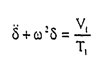
Donc les conditions initiales sont au temps t = 0 :
L'équation II a alors pour solution générale :
δ (t) = A sin ωt + B cos ωt, où A et B sont à déterminer,
et pour solution particulière :
δ (t) = A sin ωt + B cos ωt, where A and B are to be determined,
and for a specific solution:
On obtient donc la solution complète :
En exploitant les conditions initiales, il vient :
Comme t reste inférieur à la valeur T1, qui est elle-même infiniment
petite, un développement limité de l'expression ci-avant permet d'obtenir
une expression simple de l'équation de mouvement.
Soit en fin de phase 1
![]()

![]()
Comme δ est infiniment petit, on l'assimilera en début de la phase 2
à 0.As δ is infinitely small, we will assimilate it at the start of
Les nouvelles conditions initiales sont donc pour t = 0
![]()
![]()
L'équation différentielle est modifiée :
![]()
![]()
Elle a pour solution générale
En exploitant les conditions initiales, il vient
Ce déplacement relatif δ de la masse 40 m par rapport à l'ensemble
mobile 20, en fonction du temps, est représenté sur la figure 4. On peut y
voir que le déplacement relatif δ maximum est obtenu pour le quart de la
période, soit pour une valeur du temps
Pendant ce temps, le déplacement axial x de l'ensemble mobile 20
par rapport à l'ensemble fixe 10 est limité à
Par exemple, si on veut limiter la vitesse d'attaque V1 = 1 m/s et le
déplacement axial x pendant la phase 1, à X = 1 mm, le calcul donne
ω = 1571 rds/s, soit k/m = 2 464,9 kN/m kg.For example, if we want to limit the attack speed V 1 = 1 m / s and the axial displacement x during
Donc si on choisit des constantes de raideur k de 50 N/mm, 100 N/mm, 200 N/mm, il faut respectivement des masses de 20, 40 et 80 g. Ce choix des constantes de raideur n'e'st pas limitatif. D'autre part, pour ce rapport k/m, le déplacement relatif δ maximal est δmaxi = 0,3 mm.So if we choose stiffness constants k of 50 N / mm, 100 N / mm, 200 N / mm, we need masses of 20, 40 and 80 g respectively. This choice of stiffness constants is not limiting. On the other hand, for this ratio k / m, the relative displacement δ maximum is δ maxi = 0.3 mm.
Le jeu J prévisible pour un bon fonctionnement sera de l'ordre de 0,05 mm. La géométrie des moyens élastiques 30 permet alors de choisir le jeu J. On pourra, par exemple, utiliser des rondelles Siam-Ringspann standard (réf. A 10 SS 20).The play J predictable for proper operation will be of the order of 0.05 mm. The geometry of the elastic means 30 then makes it possible to choose the game J. We could, for example, use Siam-Ringspann washers standard (ref. A 10 SS 20).
Le dispositif mécanique 1, selon l'invention peut être amélioré grâce
à diverses variantes. Quelques unes de ces variantes sont présentées ci-dessous,
mais elles ne sont en aucun cas limitatives.The
Il a déjà été décrit ci-dessus un dispositif mécanique 1 amortissant le
déplacement relatif des deux ensembles 10, 20 grâce au flambage des
moyens de commande élastiques 30. Le dispositif selon l'invention peut
comporter différents types de moyens amortisseurs conçus pour amortir le
déplacement relatif des deux ensembles 10 et 20. Par exemple, les moyens
amortisseurs peuvent être avantageusement constitués par des moyens de
commande élastiques 30, comprenant au moins une rondelle travaillant au
flambage, complétés par des moyens de friction 60 conformes à ceux
décrits dans la demande de brevet français FR 2 697 881.A
Nous avons vu aussi que le dispositif mécanique 1, selon l'invention,
peut comprendre des moyens de blocage conçus pour bloquer le
déplacement relatif des deux ensembles 10, 20 si les forces de frottement
des moyens de friction sur l'ensemble fixe 10 augmentent au-delà d'une
valeur limite. Ces moyens de blocage peuvent alors comprendre au moins
une rondelle rigide dans la direction radiale, travaillant en arc-boutement.
Cette dernière peut ou non céder et libérer le déplacement relatif si l'effort
imposant ce déplacement est supérieur à un seuil prédéterminé. We have also seen that the
Comme nous l'avons vu, un dispositif mécanique 1, selon l'invention,
peut avoir des moyens de commande élastiques 30 qui comprennent au
moins une rondelle élastique intercalée entre l'ensemble mobile 20 et la
masse inertielle 40. Cependant, les moyens de commande élastiques 30
peuvent aussi comprendre un ressort, par exemple hélicoïdal, intercalé
entre une rondelle ou un ensemble de rondelles et la butée 27 de
l'ensemble mobile 20.As we have seen, a
Le dispositif mécanique 1, selon l'invention, peut aussi avoir sa
masse inertielle 40 placée sur une pièce intermédiaire 22, associée à
l'ensemble mobile 20 et mobile sur ladite pièce intermédiaire 22. Cette
variante du dispositif mécanique 1 est représentée sur la figure 5. La pièce
intermédiaire 22 comporte par exemple un anneau 23, circonférentiel à la
partie rétrécie 26 de l'ensemble mobile 20, mais avec un jeu suffisant pour
être mobile sur celui-ci. Sur l'anneau 23 s'étend radialement un épaulement
24, situé sur le bord de l'anneau 23, opposé à l'extrémité libre de
l'ensemble mobile 20 engagée dans l'ensemble fixe 10. Cet épaulement
peut prendre une forme circulaire continue ou comprendre plusieurs
éléments faisant saillie sur l'anneau 23 et répartis autour de celui-ci.
L'épaulement 24 a un encombrement circonférentiel externe inférieur au
diamètre interne du cylindre 11 de l'ensemble fixe 10, de manière à ce que
la pièce intermédiaire 22 soit libre de mouvement en translation selon l'axe
O-O, par rapport à l'ensemble fixe 10.The
La masse inertielle 40 est alors placée autour de l'anneau 23, de
manière à être libre en translation selon l'axe O-O sur l'anneau 23. On
place alors des moyens de commande élastiques 30 entre la masse mobile
40 et l'épaulement 24 et des moyens de ressort 50 entre la pièce
intermédiaire 22 et la butée 27 limitant la partie rétrécie 26 du côté opposé
à l'extrémité libre de l'ensemble mobile 20, engagée dans le cylindre 11.The
Dans un mode de réalisation avantageux du dispositif selon
l'invention, les moyens de commande élastiques 30 peuvent être constitués
d'une rondelle élastique unique et les moyens de ressort 50 d'un ensemble
de rondelles élastiques susceptibles de flamber. De cette manière, la
dynamique du déplacement est liée à une seule rondelle, qui est placée
entre la masse mobile 40 et l'épaulement 24, tandis que l'effort axial de
ressort est transmis à toutes les autres rondelles, situées entre la pièce
intermédiaire 22 et la butée 27. La rondelle élastique unique constituant les
moyens de commande élastiques 30 peut avoir une constante de raideur
plus faible que chaque rondelle dont l'ensemble constitue les moyens de
ressort 50. Ainsi la rondelle élastique unique subit plus facilement une
déformation sous l'effet de l'impulsion. En s'étendant radialement, ladite
rondelle élastique unique vient en frottement sur la paroi interne du cylindre
fixe 11, renforçant l'effet d'inertie. L'ensemble des rondelles élastiques des
moyens de ressort 50 est alors sollicité. Les rondelles de cet ensemble
s'écrasent ; leur extrémité circonférentielle externe vient au contact de la
paroi interne du cylindre 11 ; elles flambent ; et il en résulte une friction
amortissant l'impulsion. La raideur des rondelles constituant cet ensemble
peut être choisie élevée afin de maximiser les efforts de friction. Donc la
raideur de la rondelle élastique des moyens de commande élastiques 30
est choisie pour optimiser le déclenchement de la transition entre les deux
modes de déplacement relatif entre l'ensemble fixe 10 et l'ensemble mobile
20, tandis que la raideur des rondelles des moyens de ressort 50 est
choisie pour optimiser l'amortissement dudit déplacement relatif.In an advantageous embodiment of the device according to
the invention, the elastic control means 30 can be formed
of a single elastic washer and the spring means 50 of a set
elastic washers liable to buckle. In this way, the
displacement dynamics is linked to a single washer, which is placed
between the moving
On peut envisager, dans une autre .variante du dispositif selon
l'invention, de remplacer une, plusieurs, voire la totalité des rondelles des
moyens de ressort 50 susceptibles de flamber par une ou plusieurs
rondelles rigides susceptibles de s'arc-bouter entre l'ensemble fixe 10 et
l'ensemble mobile 20, lorsqu'elles sont sollicitées.One can consider, in another .variant of the device according to
the invention, to replace one, several, or even all of the washers of the
spring means 50 liable to buckle by one or more
rigid washers capable of bracing between the fixed
Avantageusement et pour optimiser la friction d'amortissement ou le
blocage, le dispositif mécanique 1 peut comprendre des moyens de
frottement, entre l'ensemble fixe 10 et l'ensemble mobile 20 (figure 6).Advantageously and to optimize the damping friction or the
blocking, the
Par exemple, un patin 60 peut être placé entre le cylindre 11 de
l'ensemble fixe 10 et les moyens de commande élastiques 30. Dans ce cas,
le patin 60 peut être une douille de révolution, fendue longitudinalement, de
diamètre externe inférieur du jeu radial J, au diamètre interne du cylindre
11. Chaque bord transversal du patin 60 comprend un épaulement 61, qui
s'étend radialement du patin 60 vers la partie rétrécie 26.For example, a
Dans ce même dispositif mécanique, des moyens de ressort 50 sont
constitués de rondelles élastiques 51 de diamètre externe au repos
approximativement égal ou légèrement inférieur au diamètre interne du
patin 60. Le diamètre interne de ces rondelles 51 est légèrement supérieur
à celui de la partie rétrécie 26. Le rayon des rondelles 51 parallèle à leur
surface principale, fait un angle de 5 à 10° par rapport au plan
perpendiculaire à l'axe O-O.In this same mechanical device, spring means 50 are
made of
L'ensemble patin 60 - moyens de ressort 50 peut avoir une masse
adaptée pour constituer en même temps la masse inertielle 40.The shoe assembly 60 - spring means 50 may have a mass
adapted to constitute at the same time the
Les moyens de commande élastiques 30, ici constitués d'un ressort
spiral, sont situés entre l'ensemble mobile 20 et les moyens de ressort 50.The elastic control means 30, here consisting of a spring
spiral, are located between the
Au repos, un jeu axial J' est ménagé entre l'épaulement 61, situé du
côté du bord du patin opposé à l'extrémité libre de l'ensemble mobile 20 et
la butée 27. L'effet technique de ce jeu J' a déjà été décrit par exemple
dans la demande de brevet français FR 2 697 881.At rest, an axial clearance J 'is provided between the
Nous avons décrit ci-dessus des dispositifs dans lesquels l'ensemble
mobile 20 coulisse dans l'ensemble fixe 10, l'amortissement ou le blocage
s'effectuant sur la surface interne du cylindre 11. Mais, des dispositifs
conformes à l'invention peuvent être conçus de telle manière que les
frottements s'effectuent sur une partie de l'ensemble mobile. On peut aussi
concevoir que le cylindre 21 soit fixe et que ce soit le cylindre 11 qui soit
mobile.We have described above devices in which the whole
mobile 20 slides in the fixed
Les dispositifs selon l'invention décrits ci-dessus peuvent aussi être compris dans des systèmes mécaniques de contrôle de déplacement plus complexes. Dans ce cas, un dispositif selon l'invention peut être placé en série ou en parallèle avec au moins un amortisseur ou un système de blocage de quelque nature que ce soit. Ceci permet d'obtenir des transitions entre déplacement amorti et déplacement libre, et réciproquement, entre deux déplacements amortis de caractéristiques différentes, ou encore une transition d'un déplacement amorti à un blocage et réciproquement, voire même une transition entre état bloqué et déplacement libre ou réciproquement.The devices according to the invention described above can also be included in mechanical displacement control systems more complex. In this case, a device according to the invention can be placed in series or in parallel with at least one shock absorber or a blocking of any kind. This allows to obtain transitions between cushioned displacement and free displacement, and conversely, between two damped displacements of characteristics different, or a transition from a damped displacement to a blockage and vice versa, or even a transition between blocked state and free movement or vice versa.
Claims (15)
- A mechanical device (1) for controlling changeover between two modes of relative displacement between two objects comprising:the device being characterized in that it further comprises:two assemblies (10, 20) capable of moving in guided relative translation, one assembly being said to be fixed (10), and the other being said to be moving (20),resilient control means (30) interposed between the two assemblies (10, 20) with controlled clearance (J) to define the mode of relative displacement; andan inertial mass (40) associated with one of the assemblies (20) and adapted to act selectively on the control means (30) as a function of the time profile of moving assembly displacement in order to modify the clearance and the mode of relative displacement.
- A device according to claim 1, characterized in that the resilient control means (30) are dimensioned to operate in buckling.
- A device according to claim 1 or 2, characterized in that it includes damper means designed to damp relative displacement between the two assemblies (10, 20).
- A device according to claim 3, characterized in that the damper means comprise at least one washer operating in buckling.
- A device according to any preceding claim, characterized in that it includes friction means (60) between the fixed assembly (10) and the moving assembly (20).
- A device according to any preceding claim, characterized in that it further comprises blocking means for blocking relative displacement between the two assemblies (10, 20) if the friction force increases beyond a limit value.
- A device according to claim 6, characterized in that the blocking means comprise at lest one washer that is rigid in its radial direction and that operates in wedging.
- A device according to claim 7, characterized in that the washer that is rigid in the radial direction is designed to give way and release relative displacement if the force imparting said displacement is greater than a predetermined threshold.
- A device according to any preceding claim, characterized in that the resilient control means comprise at least one resilient washer (30) interposed between the moving assembly (20) and the inertial mass (40).
- A device according to any preceding claim, characterized in that the inertial mass is placed on an intermediate piece (22) associated with the moving assembly (20).
- A device according to claim 9, characterized in that spring means (50) are placed between the intermediate piece (22) and the moving assembly (20).
- A device according to any preceding claim, characterized in that at least one friction shoe (60) is placed between the cylinder (11) of the fixed assembly (10) and the resilient control means (30).
- The use of the device according to any preceding claim, in mechanical systems for controlling accelerated displacement.
- The use of a device according to any preceding claim, in a high-impulse projectile launcher.
- A mechanical system for controlling displacement, characterized by the fact that it comprises a device according to any preceding claim placed in series or in parallel with at least one shock absorber or blocking means of any kind whatsoever.
Applications Claiming Priority (2)
| Application Number | Priority Date | Filing Date | Title |
|---|---|---|---|
| FR9801149A FR2774444B1 (en) | 1998-02-02 | 1998-02-02 | BIMODAL MOVEMENT MECHANICAL DEVICE |
| FR9801149 | 1998-02-02 |
Publications (2)
| Publication Number | Publication Date |
|---|---|
| EP0933552A1 EP0933552A1 (en) | 1999-08-04 |
| EP0933552B1 true EP0933552B1 (en) | 2003-05-21 |
Family
ID=9522457
Family Applications (1)
| Application Number | Title | Priority Date | Filing Date |
|---|---|---|---|
| EP99400229A Expired - Lifetime EP0933552B1 (en) | 1998-02-02 | 1999-02-02 | Mechanical device having two modes of operation |
Country Status (6)
| Country | Link |
|---|---|
| US (1) | US6364074B2 (en) |
| EP (1) | EP0933552B1 (en) |
| CA (1) | CA2261360A1 (en) |
| DE (1) | DE69907983T2 (en) |
| ES (1) | ES2198857T3 (en) |
| FR (1) | FR2774444B1 (en) |
Families Citing this family (8)
| Publication number | Priority date | Publication date | Assignee | Title |
|---|---|---|---|---|
| US6672575B2 (en) * | 2001-06-12 | 2004-01-06 | Lord Corporation | Surface effect damper |
| US20030168295A1 (en) * | 2002-02-12 | 2003-09-11 | Zhixiu Han | Active vibration isolation system |
| FR2869662B1 (en) * | 2004-04-30 | 2006-06-23 | Lacroix Soc E | ADAPTABLE FRICTION SHOCK DEVICE |
| FR2869663B1 (en) * | 2004-04-30 | 2006-06-23 | Lacroix Soc E | FRICTION SHOCK ABSORBER DEVICE |
| WO2007031611A1 (en) * | 2005-09-15 | 2007-03-22 | Etienne Lacroix Tous Artifices S.A. | Damping device with adaptable friction |
| US20070246785A1 (en) * | 2006-04-20 | 2007-10-25 | Asml Netherlands B.V. | Locking device, adjustment mechanism and lithographic apparatus |
| DE102016210790A1 (en) * | 2016-06-16 | 2017-12-21 | Zf Friedrichshafen Ag | Damping valve device with progressive damping force characteristic |
| DE102019215558A1 (en) * | 2019-10-10 | 2021-04-15 | Zf Friedrichshafen Ag | Throttle point for a vibration damper |
Family Cites Families (10)
| Publication number | Priority date | Publication date | Assignee | Title |
|---|---|---|---|---|
| US2539275A (en) * | 1945-09-22 | 1951-01-23 | Bofors Ab | Forward damper device for firearms with a recoil mantle |
| US2459537A (en) * | 1946-05-27 | 1949-01-18 | Peter B Oberstadt | Dampening devices for shock absorbers and the like |
| FR1122015A (en) * | 1955-02-01 | 1956-08-30 | Friction damper | |
| BE548536A (en) * | 1956-06-11 | |||
| FR2127224A5 (en) * | 1971-03-01 | 1972-10-13 | Int Vibration Engin | |
| DE2240943A1 (en) * | 1972-08-19 | 1974-02-28 | Adalbert Freyler | SHOCK AND VIBRATION ABSORBERS IN TELESCOPIC SHAPE, IN PARTICULAR FOR VEHICLES |
| FR2333165A1 (en) * | 1975-11-26 | 1977-06-24 | Quillery | Shock absorber for vehicle bumper - with energy absorbed by friction between polyacetal and polyphenylene oxide surfaces |
| SU868183A1 (en) * | 1980-01-14 | 1981-09-30 | Предприятие П/Я Р-6896 | Dry friction damper |
| DE4018599A1 (en) * | 1989-07-10 | 1991-01-24 | Miele & Cie | FRICTION DAMPER, ESPECIALLY FOR DRUM WASHING MACHINES |
| FR2697881B1 (en) * | 1992-11-06 | 1995-01-27 | Lacroix E Tous Artifices | Damping device for mechanical system. |
-
1998
- 1998-02-02 FR FR9801149A patent/FR2774444B1/en not_active Expired - Fee Related
-
1999
- 1999-02-01 US US09/241,971 patent/US6364074B2/en not_active Expired - Fee Related
- 1999-02-01 CA CA002261360A patent/CA2261360A1/en not_active Abandoned
- 1999-02-02 EP EP99400229A patent/EP0933552B1/en not_active Expired - Lifetime
- 1999-02-02 ES ES99400229T patent/ES2198857T3/en not_active Expired - Lifetime
- 1999-02-02 DE DE69907983T patent/DE69907983T2/en not_active Expired - Fee Related
Also Published As
| Publication number | Publication date |
|---|---|
| FR2774444A1 (en) | 1999-08-06 |
| US20020000351A1 (en) | 2002-01-03 |
| FR2774444B1 (en) | 2000-05-19 |
| DE69907983D1 (en) | 2003-06-26 |
| EP0933552A1 (en) | 1999-08-04 |
| US6364074B2 (en) | 2002-04-02 |
| DE69907983T2 (en) | 2004-02-19 |
| ES2198857T3 (en) | 2004-02-01 |
| CA2261360A1 (en) | 1999-08-02 |
Similar Documents
| Publication | Publication Date | Title |
|---|---|---|
| EP2607743B1 (en) | Damping device with friction damping means. | |
| EP3190310B1 (en) | Pendulum damping device | |
| CA2956917C (en) | Aircraft landing gear including a main shock absorber and a secondary, anti-shimmy shock absorber | |
| FR2680212A1 (en) | CLUTCH DISC FOR A FRICTION CLUTCH OF A MOTOR VEHICLE. | |
| FR2511456A1 (en) | DEVICE FOR TRANSMITTING THE ROTATION TORQUE, IN PARTICULAR FOR A CLUTCH DISC | |
| FR2767888A1 (en) | TORSION OSCILLATION SHOCK ABSORBER | |
| EP0933552B1 (en) | Mechanical device having two modes of operation | |
| WO2015140456A1 (en) | Damping device for drive chain of a vehicle | |
| FR2771466A1 (en) | ROTATION SWING SHOCK ABSORBER | |
| EP3190045B1 (en) | A landing-gear assembly for an aircraft, the landing-gear assembly including a secondary shimmy damper | |
| WO2017072338A1 (en) | Vibration damper | |
| FR3014519A1 (en) | TORSION DAMPING DEVICE WITH IMPROVED FILTRATION EFFICIENCY PENDULUM | |
| FR2769676A1 (en) | TORSION SHOCK ABSORBER | |
| FR3039872A1 (en) | BEARING MEMBER FOR TORSION OSCILLATION DAMPING DEVICE | |
| FR3051869A1 (en) | TORQUE TRANSMISSION DEVICE, IN PARTICULAR FOR A MOTOR VEHICLE | |
| FR2809150A1 (en) | Damper used between the IC engine and the gearbox of a car has compression spring and elastic element mounted in series between a entry element and an exit element | |
| WO2019115479A1 (en) | Rolling member for a pendular damping device | |
| WO2019110310A1 (en) | Pendular centrifuge damping device | |
| CA2563794A1 (en) | Rapid recovery shock absorber system with hydraulic end stop and method for use thereof | |
| EP3199830B1 (en) | Pendulum damping device | |
| FR3067430A1 (en) | PENDULAR DAMPING DEVICE | |
| FR3046647A1 (en) | PENDULAR DAMPING DEVICE | |
| FR3052520A1 (en) | METHOD OF MAKING A PENDULUM DAMPING DEVICE | |
| EP1978277B1 (en) | Compensation module for a hydraulic shock absorber of a vehicle and shock absorber equipped with such a compensation module | |
| FR3048271A1 (en) | PENDULAR DAMPING DEVICE |
Legal Events
| Date | Code | Title | Description |
|---|---|---|---|
| PUAI | Public reference made under article 153(3) epc to a published international application that has entered the european phase |
Free format text: ORIGINAL CODE: 0009012 |
|
| AK | Designated contracting states |
Kind code of ref document: A1 Designated state(s): BE DE ES FR GB SE |
|
| AX | Request for extension of the european patent |
Free format text: AL;LT;LV;MK;RO;SI |
|
| RTI1 | Title (correction) |
Free format text: MECHANICAL DEVICE HAVING TWO MODES OF OPERATION |
|
| 17P | Request for examination filed |
Effective date: 20000124 |
|
| AKX | Designation fees paid |
Free format text: BE DE ES FR GB SE |
|
| GRAH | Despatch of communication of intention to grant a patent |
Free format text: ORIGINAL CODE: EPIDOS IGRA |
|
| GRAH | Despatch of communication of intention to grant a patent |
Free format text: ORIGINAL CODE: EPIDOS IGRA |
|
| GRAA | (expected) grant |
Free format text: ORIGINAL CODE: 0009210 |
|
| AK | Designated contracting states |
Designated state(s): BE DE ES FR GB SE |
|
| REG | Reference to a national code |
Ref country code: GB Ref legal event code: FG4D Free format text: NOT ENGLISH |
|
| REF | Corresponds to: |
Ref document number: 69907983 Country of ref document: DE Date of ref document: 20030626 Kind code of ref document: P |
|
| REG | Reference to a national code |
Ref country code: SE Ref legal event code: TRGR |
|
| GBT | Gb: translation of ep patent filed (gb section 77(6)(a)/1977) |
Effective date: 20030730 |
|
| REG | Reference to a national code |
Ref country code: ES Ref legal event code: FG2A Ref document number: 2198857 Country of ref document: ES Kind code of ref document: T3 |
|
| PLBE | No opposition filed within time limit |
Free format text: ORIGINAL CODE: 0009261 |
|
| STAA | Information on the status of an ep patent application or granted ep patent |
Free format text: STATUS: NO OPPOSITION FILED WITHIN TIME LIMIT |
|
| 26N | No opposition filed |
Effective date: 20040224 |
|
| PGFP | Annual fee paid to national office [announced via postgrant information from national office to epo] |
Ref country code: SE Payment date: 20070118 Year of fee payment: 9 |
|
| PGFP | Annual fee paid to national office [announced via postgrant information from national office to epo] |
Ref country code: GB Payment date: 20070209 Year of fee payment: 9 Ref country code: DE Payment date: 20070209 Year of fee payment: 9 |
|
| PGFP | Annual fee paid to national office [announced via postgrant information from national office to epo] |
Ref country code: ES Payment date: 20070215 Year of fee payment: 9 |
|
| PGFP | Annual fee paid to national office [announced via postgrant information from national office to epo] |
Ref country code: BE Payment date: 20070228 Year of fee payment: 9 |
|
| PGFP | Annual fee paid to national office [announced via postgrant information from national office to epo] |
Ref country code: FR Payment date: 20070228 Year of fee payment: 9 |
|
| BERE | Be: lapsed |
Owner name: S.A. ETIENNE *LACROIX - TOUS ARTIFICES Effective date: 20080228 |
|
| EUG | Se: european patent has lapsed | ||
| GBPC | Gb: european patent ceased through non-payment of renewal fee |
Effective date: 20080202 |
|
| REG | Reference to a national code |
Ref country code: FR Ref legal event code: ST Effective date: 20081031 |
|
| PG25 | Lapsed in a contracting state [announced via postgrant information from national office to epo] |
Ref country code: SE Free format text: LAPSE BECAUSE OF NON-PAYMENT OF DUE FEES Effective date: 20080203 Ref country code: DE Free format text: LAPSE BECAUSE OF NON-PAYMENT OF DUE FEES Effective date: 20080902 |
|
| PG25 | Lapsed in a contracting state [announced via postgrant information from national office to epo] |
Ref country code: BE Free format text: LAPSE BECAUSE OF NON-PAYMENT OF DUE FEES Effective date: 20080228 |
|
| PG25 | Lapsed in a contracting state [announced via postgrant information from national office to epo] |
Ref country code: FR Free format text: LAPSE BECAUSE OF NON-PAYMENT OF DUE FEES Effective date: 20080229 |
|
| REG | Reference to a national code |
Ref country code: ES Ref legal event code: FD2A Effective date: 20080204 |
|
| PG25 | Lapsed in a contracting state [announced via postgrant information from national office to epo] |
Ref country code: GB Free format text: LAPSE BECAUSE OF NON-PAYMENT OF DUE FEES Effective date: 20080202 |
|
| PG25 | Lapsed in a contracting state [announced via postgrant information from national office to epo] |
Ref country code: ES Free format text: LAPSE BECAUSE OF NON-PAYMENT OF DUE FEES Effective date: 20080204 |