EP0933315B1 - Ausrichtvorrichtung - Google Patents
Ausrichtvorrichtung Download PDFInfo
- Publication number
- EP0933315B1 EP0933315B1 EP97943193A EP97943193A EP0933315B1 EP 0933315 B1 EP0933315 B1 EP 0933315B1 EP 97943193 A EP97943193 A EP 97943193A EP 97943193 A EP97943193 A EP 97943193A EP 0933315 B1 EP0933315 B1 EP 0933315B1
- Authority
- EP
- European Patent Office
- Prior art keywords
- seed
- shooter
- seeding
- aligned
- shutter
- Prior art date
- Legal status (The legal status is an assumption and is not a legal conclusion. Google has not performed a legal analysis and makes no representation as to the accuracy of the status listed.)
- Expired - Lifetime
Links
Images






Classifications
-
- A—HUMAN NECESSITIES
- A01—AGRICULTURE; FORESTRY; ANIMAL HUSBANDRY; HUNTING; TRAPPING; FISHING
- A01C—PLANTING; SOWING; FERTILISING
- A01C1/00—Apparatus, or methods of use thereof, for testing or treating seed, roots, or the like, prior to sowing or planting
- A01C1/04—Arranging seed on carriers, e.g. on tapes, on cords ; Carrier compositions
-
- B—PERFORMING OPERATIONS; TRANSPORTING
- B65—CONVEYING; PACKING; STORING; HANDLING THIN OR FILAMENTARY MATERIAL
- B65G—TRANSPORT OR STORAGE DEVICES, e.g. CONVEYORS FOR LOADING OR TIPPING, SHOP CONVEYOR SYSTEMS OR PNEUMATIC TUBE CONVEYORS
- B65G47/00—Article or material-handling devices associated with conveyors; Methods employing such devices
- B65G47/02—Devices for feeding articles or materials to conveyors
- B65G47/04—Devices for feeding articles or materials to conveyors for feeding articles
- B65G47/12—Devices for feeding articles or materials to conveyors for feeding articles from disorderly-arranged article piles or from loose assemblages of articles
- B65G47/14—Devices for feeding articles or materials to conveyors for feeding articles from disorderly-arranged article piles or from loose assemblages of articles arranging or orientating the articles by mechanical or pneumatic means during feeding
- B65G47/1407—Devices for feeding articles or materials to conveyors for feeding articles from disorderly-arranged article piles or from loose assemblages of articles arranging or orientating the articles by mechanical or pneumatic means during feeding the articles being fed from a container, e.g. a bowl
-
- B—PERFORMING OPERATIONS; TRANSPORTING
- B65—CONVEYING; PACKING; STORING; HANDLING THIN OR FILAMENTARY MATERIAL
- B65G—TRANSPORT OR STORAGE DEVICES, e.g. CONVEYORS FOR LOADING OR TIPPING, SHOP CONVEYOR SYSTEMS OR PNEUMATIC TUBE CONVEYORS
- B65G47/00—Article or material-handling devices associated with conveyors; Methods employing such devices
- B65G47/02—Devices for feeding articles or materials to conveyors
- B65G47/04—Devices for feeding articles or materials to conveyors for feeding articles
- B65G47/12—Devices for feeding articles or materials to conveyors for feeding articles from disorderly-arranged article piles or from loose assemblages of articles
- B65G47/14—Devices for feeding articles or materials to conveyors for feeding articles from disorderly-arranged article piles or from loose assemblages of articles arranging or orientating the articles by mechanical or pneumatic means during feeding
- B65G47/1407—Devices for feeding articles or materials to conveyors for feeding articles from disorderly-arranged article piles or from loose assemblages of articles arranging or orientating the articles by mechanical or pneumatic means during feeding the articles being fed from a container, e.g. a bowl
- B65G47/1414—Devices for feeding articles or materials to conveyors for feeding articles from disorderly-arranged article piles or from loose assemblages of articles arranging or orientating the articles by mechanical or pneumatic means during feeding the articles being fed from a container, e.g. a bowl by means of movement of at least the whole wall of the container
-
- B—PERFORMING OPERATIONS; TRANSPORTING
- B65—CONVEYING; PACKING; STORING; HANDLING THIN OR FILAMENTARY MATERIAL
- B65G—TRANSPORT OR STORAGE DEVICES, e.g. CONVEYORS FOR LOADING OR TIPPING, SHOP CONVEYOR SYSTEMS OR PNEUMATIC TUBE CONVEYORS
- B65G47/00—Article or material-handling devices associated with conveyors; Methods employing such devices
- B65G47/22—Devices influencing the relative position or the attitude of articles during transit by conveyors
- B65G47/24—Devices influencing the relative position or the attitude of articles during transit by conveyors orientating the articles
Definitions
- the present invention relates to an alignment apparatus, such as a seeding machine which, in a pre-process of grafting vegetable seedlings such as cucumbers and pumpkins, aligns and seeds flat seeds of the vegetables so as to align cotyledon of the vegetable seedlings in a substantially uniform direction, and various work machines which align harvested products such as cucumbers in a uniform direction and mechanically select, pack, and process the products.
- an alignment apparatus such as a seeding machine which, in a pre-process of grafting vegetable seedlings such as cucumbers and pumpkins, aligns and seeds flat seeds of the vegetables so as to align cotyledon of the vegetable seedlings in a substantially uniform direction
- various work machines which align harvested products such as cucumbers in a uniform direction and mechanically select, pack, and process the products.
- An alignment apparatus corresponding to the upper clause of claim 1 is known from FR-A-2 453 802.
- grafting means as one of means for automatically grafting vegetable seedlings, for example.
- This grafting means binds upper and lower portions of a stem of a stock and scion nursery plant transported on a transport line using a binding hand, and cuts a middle portion of the held stock and scion nursery plant using a cutter, and grafts the lower stem of the cut stock on the upper stem of the scion nursery plant.
- this grafting method since the grafting is carried out in the vicinity of the base portions where cotyledons of the seedlings are developed, it is necessary to bind the base portions where the cotyledons are developed by using the binding hand.
- the present invention refers to an alignment apparatus according to claim 1 and an alignment apparatus for a seeding machine according to claim 2. Further embodiments are described in the dependent claims.
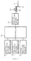
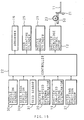
- FIG. 1 is a control circuit diagram
- FIG. 2 is a whole plan view
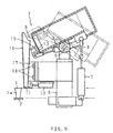
- FIG. 3 is an explanatory side view showing a seeding machine
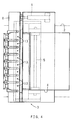
- FIG. 4 is an explanatory plan view showing the seeding machine
- a seeding machine 3 is provided on a seeding conveyor 2 which transports a seeding tray 1.
- the seeding machine 3 has a seed hopper 4, a hopper receiver 6, an electro-hydraulic-air hopper swinging cylinder 7, a seed supply plate 8, an electro-hydraulic-air supply plate open/close cylinder 9, a seed shooter 10, a seeding shutter 11, and a shutter open/close control motor 12.
- the seed hopper 4 stores flat seeds A such as cucumbers and pumpkins to be aligned.
- the hopper receiver 6, which is fixed to a rest of the seeding conveyor 2, supports a middle portion of the seed hopper 4 via a swing support shaft 5 so as to be swingable to forward and backward.
- the hopper swinging cylinder 7, which is provided between the seed hopper 4 and hopper receiver 6, swings the seed hopper 4 forward and backward.
- the seed supply plate 8 is provided at an opening of the seed hopper 4 which is on the opposite side of the hopper swinging cylinder 7 so as to open/close the opening.
- the supply plate open/close cylinder 9 allows the seed supply plate 8 to open/close the opening.
- the seed shooter 10 is a guide member which brings an upper end opening portion below the opened position of the seed supply plate 8.
- the seeding shutter 11 is a mounting member, which is provided closely to the upper surface of the seeding tray 1 on the seeding conveyor 2 and which opens/closes a lower end opening of the seed shooter 10 and places the seeds A in the state the lower end opening is opened.
- the shutter open/close control motor 12 opens/closes the seeding shutter 11.
- the seeding machine 3 is constituted so that seeds taken out of the seed hopper 4 onto the seed supply plate 8 one by one are discharged down into respective pot portions 1a of the seeding tray 1 via the seed shooter 10 so that seeding is carried out.
- nozzle holes 13 for sucking seeds is formed in the seed supply plate 8 correspondingly to the pot portions 1a arranged laterally (right-and-left) in the seeding tray 1, and suction paths 14 which interconnect to each nozzle hole 13 are formed in a suction case 15 so that the seeds A are sucked one by one into each nozzle hole 13 in the seed supply plate 8 by a vacuum suction force of an absorber 16 such as a vacuum pump which is connected with the suction paths 14.
- an absorber 16 such as a vacuum pump which is connected with the suction paths 14.
- the seeds A are sucked into the nozzle holes 13 by the suction force of the absorber 16 in the state the seed supply plate 8 is in the closed state while the seed hopper 4 is swung once or twice from a forward-down and backward-up posture to a forward-up and backward-down posture or the forward-up and backward-down posture to the forward-down and forward-up posture.
- the suction of the nozzle holes 13 is stopped so that the seeds A on the seed supply plate 8 are introduced into the seed shooter 10.
- the seed shooter 10 is formed so as to have a rectangular cross section in plane view, and to be narrowed at a lower end. Moreover, the seed shooter 10 is formed so that a longitudinal width T in the forward-backward direction of the lower end cross section is slightly larger than a short diameter portion of the seeds A, and a transversal width W is larger than the longitudinal width T (W>T) and is slightly larger than a long diameter portion of the seeds A.
- a longitudinal direction of the seeds A is aligned with the right-and-left transversal direction to a certain degree while the seed shooter 10 drops down, and the seeding shutter 11 is brought into the open state, and when the seeds A are discharged from the seed shooter 10, the seeds A are brought into contact with an inner side surface on the backward side of the seed shooter 10 by a slide-opening force of the seeding shutter 11 which substantially intersects perpendicularly to the transversal width W.
- seeds which are not uniform only by the seed shooter 10 (for example, the seeds in the standing posture) are aligned in a substantially uniform direction, namely, in the right-and-left transversal direction.
- any seed shooters may be used as long as they have a longer and shorter portion, such as oval shapes.
- a seeding groove C having a V-shape viewed from the side is previously formed on a surface of nutritious solid B charged into each pot portion 1a of the seeding tray 1 by using a suppressing tool or the like, and it helps the posture of the seeds A in the transversal direction discharged from the seed shooter 10 to be maintained so that the alignment accuracy is further improved.
- the seed shooters 10 whose number accords with a number of the nozzle holes 13 are mounted integrally to a mounting plate 17, and they are fixed onto the hopper receiver 6 via bolts 18 so as to be replaceable with ones having various shapes according to types of the seeds A.
- the shutter open/close control motor 12 changes the open/close speed of the seeding shutter 11 suitably with a rotational speed of the shutter open/close control motor 12 being shifted by controlling a voltage, resistance, or magnetic field.
- the shutter open/close control motor 12 has a shutter low-speed opening determinator 19, which determines a low-speed value when the seeding shutter 11 is opened at a low-speed, a shutter high-speed opening determinator 20, which determines a high-speed value when the seeding shutter 11 is opened at a high-speed, and a speed shifting position sensor 21, which shifts the opening speed of the seeding shutter 11 from the low-speed to the high-speed based on results of detecting the opening.
- the opening determinators 19 and 20 and the speed shifting position sensor 21 are connected with the shutter open/close control motor 12 via a controller 22, and the opening/closing speed of the seeding shutter 11 is changed suitably via a pinion 23 and a rack gear 50 by changing the speed of the shutter open/close control motor 12.
- the posture of the seed hopper 4 is changed into the forward-up and backward-down posture, and the seed supply plate 8 which closes the opening portion of the seed hopper 4 is brought into the open state. Then, the suction of the nozzle holes 13 by the absorber 16 is stopped, and the seeds A on the seed supply plate 8 are introduced down into the seed shooter 10. Next, when the seeding shutter 11 is operated to be opened, seeding is carried out into each pot portion 1a of the seeding tray 1. At this time, the longitudinal directions of the seeds A are aligned with the transversal direction by rectangular regulation of the seed shooter 10 and a pulling action during the opening of the seeding shutter 11, and thus the aligned seeding are carried out.
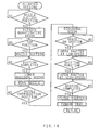
- the low-speed and high-speed values in the state that the seeding shutter is opened determined by the opening determinators 19 and 20 are inputted into the controller 22, and the seeds A are introduced into the seed shooter 10 so that the seeding shutter 11 is started to be opened.
- the seeding shutter 11 is gradually opened at the low-speed, and when a suitable open state (for example, half-opened) of the seeding shutter 11 is detected by the speed shifting position sensor 21 during the opening operation, the seeding shutter 11 is shifted into the high-speed so as to be opened at a high-speed the latter half of the opening operation.
- the seeding shutter 11 is closed at a high-speed.
- the most suitable shutter opening speeds exist according to respective types of the seeds A, the most suitable low-speed and high-speed shutter opening speeds can be stepless-regulated accordingly by the opening determinators 19 and 20.
- the functions and effects which are the same as those in the aforementioned embodiment can be obtained by a constitution such that, as represented by a solid line, as the opening speed of the seeding shutter 11 is shifted into the close to the open state, the opening speed is stepless-regulated.
- FIG. 13 shows a seed-quantitative seeding machine 3a whose seeding hopper is fixed in a position, and it has a seed hopper 4, a quantitative seed rack 24, an elevating cylinder 25, a plurality of seed suction nozzles 26, a nozzle supporting tube 27, an introduction pipe 28, a nozzle moving cylinder 29, a seed shooter 10, seeding shutter 11, and a shutter open/close control motor 12.
- the seed hopper 4, whose position is fixed, houses seeding seeds A.
- the quantitative seed rack 24 raises a constant number of the seeds A (5 to 6) from the seed hopper 4 to a constant height.
- the elevating cylinder 25 raises and lowers the quantitative seed rack 24.
- the introduction pipe 28 brings the seeds A to be sucked adjacently to the seed hopper 4 so as to discharge them to the tips of the seed suction nozzles 26.
- the nozzle moving cylinder 29 moves the tips of the seed suction nozzles 26 above the quantitative seed rack 24 or introduction pipe 28.
- the seed shooter 10 brings the seeds A to be introduced below the introduction pipe 28 so as to drop them downward.
- the seeding shutter 11 opens/closes the lower end opening of the seed shooter 10.
- the shutter open/close control motor 12 controls the seeding shutter 11 to perform the opening/closing operation.
- the seeding machine 3a is constituted so that one seed A sucked to the tip of the suction nozzle 26 is introduced into the seed shooter 10 via the introduction pipe 28, and seeding is carried out while the seeding shutter 11 is opened.
- the seeding machine has a nozzle position sensor 30a, a seed rack position sensor 30b, a seed sensor 31, and an absorber 16.
- the nozzle position sensor 30a detects moving positions of the seed suction nozzles 26.
- the seed rack position sensor 30b detects an elevating position of the quantitative seed rack 24.
- the seed sensor 31 detects the seeds A on the seeding shutter 11.
- the absorber 16 generates a vacuum suction force in the suction path 14.
- the seeds A on the quantitative seed rack 24 is raised so as to approach the closest to the seed suction nozzles 26. At this time, the seeds A are sucked to the tip of the seed suction nozzle 26 by the vacuum suction force one by one, and thereafter the residual seeds A on the quantitative seed rack 24 are lowered, and the seed suction nozzles 26 are moved towards the introduction pipe 28.
- the sucked seeds A are discharged into the seed shooter 10 via the introduction pipe 28, and when the discharged seeds A are on the seeding shutter 11, as mentioned above, the seeding shutter 11 is opened at the low-speed in the first half opening operation and at the high-speed in the latter half opening operation so that aligned seeding is carried out. Thereafter, the seeding shutter 11 is closed at the high-speed, and the seeding tray 1 is advanced by one pitch for a pot so that the pot portion 1a for the next seeding waits below the seed shooter 10.
- the seed shooter 10 is made of soft and flexible material and at least its lower end has a circular pipe shape.
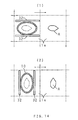
- a pair of movable pressing members 32 which are provided so as to face each other via the seed shooter 10, are moved at the lower end of the seed shooter 10, and the cross section of the lower end of the seed shooter is deformed into a oval shape by the applied pressure to the pressing member 32 so that the aligned seeding in which the postures of the seeds A are aligned is made to be possible.
- forward-backward seeding in which the longitudinal direction (longer diameter portion) of the seeds A are set in the forward-backward direction with respect to the respective pot portions 1a, laterally aligned as shown in FIG. 14(1), and right-left seeding in which the longitudinal direction of the seeds A is set in the right-left direction as shown in FIG. 14(2), are made to be possible.
- the movement of the pressing members 32 is adjusted by operating adjusting means for adjusting the movement of the pressing members 32, the applied pressure of the pressing members 32 is suitably adjusted, and the oval shape of the lower end cross section of the seed shooter 10 is deformed so as to have various dimensions.
- various seeds of such as a cucumber and a pumpkin can put into the single seed shooter 10, so even if flat state and size of the seeds A are varied according to types of the seeds A, the single seed shooter 10 can be used widely for the various seeds A because of its opening which suitably copes with the various seeds A without inconvenience such that the longitudinal direction (longer diameter portion) of the seeds A are not caught in the seed shooter 10.
- the lower end of the seed shooter 10 may be made of soft and flexible material, and such a seed shooter 10 made of soft and flexible material may be used in the aforementioned seeding machine 3.
- the present invention is used for, for example, a sorting work in sorting (grading) facilities in which vegetables and fruits are aligned in a uniform direction, a packing work in a packing machine in which vegetables and fruits are aligned in a uniform direction, a processing work in food processing facilities in which vegetables and fruits are aligned in a uniform direction, and hulled ratio and class judgment work in which threshed and unpolished rice is aligned in a uniform direction in a rice hulling machine.
- grade sorting
- FIGS. 17 and 18 show a cucumber packing machine 33 for aligning cucumbers K to be aligned in a uniform direction and packing them as one example.
- the cucumber packing machine 33 has a transport conveyor 34, an endless-type circulating conveyor 37, a box transport conveyor 39, a packing device 40, and a carrying-out conveyor 41.
- the transport conveyor 34 supplies the harvested cucumbers K.
- the circulating conveyor 37 place the cucumbers K from the transport conveyor 34 into a tray 35 so as to successively transports them to a packing position.
- the transport conveyor 39 transports a packing box 38 at the packing position.
- the packing device 40 packs the cucumbers K in the packing box 38 at the packing position.
- the carrying-out conveyor 41 carries out the packing box 38 into which the cucumbers K were packed.
- An aligning apparatus 42 which is composed of a seed shooter 10a as a guide member and a seeding shutter 11a as a mounting member, is provided in a joint portion between the transport conveyor 34 and circulating conveyor 37, and this apparatus aligns the cucumbers K from the transport conveyor 34 in a uniform direction so as to put onto the tray 35.
- the posture of the cucumbers K is aligned in a uniform direction (in FIG. 18, the opening direction of the seeding shutter 11a intersects perpendicularly to the longitudinal direction of the cucumbers K) by the relative motion between the seed shooter 10a and seeding shutter 11a for varying the opening speed of the seed shutter 11a. Therefore, the shapes and sizes of the seed shooter 10a and seeding shutter 11a, whose shapes and sizes are suitable for objects to be aligned, are used.
- FIG. 19 shows an alignment apparatus 42 which is constituted so that a guide member 43, for arranging cucumbers K in plural lines so as to guide them in the vertical posture, is provided above transport conveyors 34a and 34b as mounting members for supplying the harvested cucumbers K, and forward and backward shutters 44 and 45, for maintaining one cucumber in each line on the transport surface of the transport conveyor 34a on the feed end side, are provided so that the transport conveyor 34a can move (one-way motion or round-trip motion) in a direction which intersects perpendicularly to the transport direction.
- a guide member 43 for arranging cucumbers K in plural lines so as to guide them in the vertical posture
- transport conveyors 34a and 34b as mounting members for supplying the harvested cucumbers K
- forward and backward shutters 44 and 45 for maintaining one cucumber in each line on the transport surface of the transport conveyor 34a on the feed end side
- the transport conveyor 34a When the cucumbers K stay between the forward and backward shutters 44 and 45 on the transport conveyor 34a, the transport conveyor 34a is moved in the direction which intersects perpendicularly to the transport direction, the longitudinal direction of the cucumbers K is along the guide member 43 in static and fixed state so that its posture is adjusted. Thereafter, when the shutters 44 and 45 are opened, the cucumbers K which are in the vertical posture and are aligned in a sideway line on the transport surface of the transport conveyor 34a, are fed into the circulating conveyor 37.
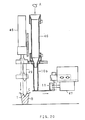
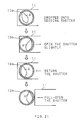
- FIGS. 20 and 21 show a constitution which opens the seeding shutter 11 at two steps.
- a cylindrical seed shooter 10b for introducing the seeds A in the seed hopper 4 via a cylindrical upper guide body 46, and the seeding shutter 11, for opening/closing the lower end opening of the seed shooter 10b using an open/close cylinder 47, are provided, and the seeds A, which are discharged out of the seed shooter 10b when the seeding shutter 11 is opened, are dropped into a V-shaped seeding groove C which is formed by a suppressing tool 49 elevated by a suppression elevating cylinder 48.
- the seeding shutter 11 is opened slightly, and the seeds A are brought into contact with an inner wall of the cylindrical seed shooter 10b and are aligned.
- the seeding shutter 11 is returned to the full-closed position, also the seeds A in the standing posture are laid so as to be in the sideway direction.
- the seeding shutter 11 is in the second step, namely, in the full-open state, the seeds A are aligned by the seed shooter 10b, and the dropping position of the seeds A is regulated so that the seeds A, which are aligned in the sideway posture, are dropped into the seeding groove C on the nutritious soil B in the seeding tray 1 at the fixed position.
- the seeding whose alignment accuracy is improved is carried out. Namely, after the seeding shutter 11 is moved in one direction on the open/close side, it is moved in the opposite direction (first step), and it is full-opened (second step). As a result, the alignment accuracy is improved, and this operation may be repeated plural times.
- the present invention is effective as an alignment apparatus for flat seeds, and as an alignment apparatus for mechanically selecting, packing, processing, etc. products having a length.
Landscapes
- Engineering & Computer Science (AREA)
- Mechanical Engineering (AREA)
- Life Sciences & Earth Sciences (AREA)
- Soil Sciences (AREA)
- Environmental Sciences (AREA)
- Sowing (AREA)
Claims (7)
- Eine Ausrichtungsvorrichtung, umfassend: ein Führungselement (10) zum Definieren einer Ausrichtungsrichtung eines auszurichtenden Objekts (A), dessen Ausrichtungsrichtung vorbestimmt ist; und ein Montageelement (11) zur Montagen des auszurichtenden Objekts (A) auf einer Montagefläche davon; wobei eine Haltung des auszurichtenden Objekts (A) in einer einheitlichen Richtung durch eine relative Bewegung zwischen dem Führungselement (10) und dem Montageelement (11) ausgerichtet wird, in einem Zustand, in dem das auszurichtende Objekt (A) auf der Montagefläche montiert wird, dadurch gekennzeichnet, dassdas Montageelement (11) gegen das Führungselement (10) sequenzielle Vorgänge durchführt, umfassend: eine erste Operation zum Durchführen einer relativen Verlagerung in eine Richtung; eine zweite Operation zum Durchführen einer relativen Verlagerung in eine entgegengesetzte Richtung zu der einen Richtung; und eine dritte Operation zum Durchführen einer relativen Verlagerung in die eine Richtung, deren Verlagerungsbetrag größer ist als der Gleiche bei der zweiten Operation, wobeiwährend der ersten Operation, wenn das auszurichtende Objekt (A) nicht mit einer inneren Seitenwand des Führungselements (10) in Kontakt ist, eine Ausrichtungsrichtung des auszurichtenden Objekts (A) in die Ausrichtungsrichtung orientiert wird, die durch das Führungselement (10) definiert ist,während der zweiten Operation, wenn das auszurichtende Objekt (A) mit der inneren Seitenwand des Führungselements (10) in Kontakt gewesen ist bevor die erste Operation startete, das auszurichtende Objekt (A) von der inneren Seitenwand des Führungselements (10) getrennt wird, undwährend der dritten Operation eine Ausrichtungsrichtung des auszurichtenden Objekts (A) in der Ausrichtungsrichtung orientiert wird, die durch das Führungselement (10) definiert ist.
- Eine Ausrichtungsvorrichtung für eine Sämaschine, umfassend: eine Saatgutrutsche (10) zum nacheinander darin Einbringen von Saatgut von einem Saatgutbehälter (4); und einen Saatgutverschluss (11) zum Öffnen/Schließen eines unteren Endausgangs der Saatgutrutsche (10); wobei ein Aussäen durch in Haltung bringen des Saatguts (A) durch eine relative Bewegung zwischen der Saatgutrutsche (10) und dem Saatgutverschluss (11), in einem Zustand, in dem das Saatgut (A) auf dem Saatgutverschluss (11) gehalten wird, und ein Öffnungsvorgang des Saatgutverschlusses (11) durchgeführt wird, dadurch gekennzeichnet, dassder Saatgutverschluss (11) gegen die Saatgutrutsche (10) sequenzielle Vorgänge durchführt, umfassend: eine erste Operation zum Durchführen einer relativen Verlagerung in die Öffnungsrichtung; eine zweite Operation zum Durchführen einer relativen Verlagerung in Verschlussrichtung entgegengesetzt der Öffnungsrichtung; und eine dritte Operation zum Durchführen einer relativen verlagerung in die Öffnungsrichtung, um ganz geöffnet zu sein, wodurch,während der ersten Operation, wenn das Saatgut (A) nicht mit einer inneren Seitenwand der Saatgutrutsche (10) in Kontakt ist, eine Ausrichtungsrichtung des Saatguts (A) in der Ausrichtungsrichtung orientiert wird, welche durch die Saatgutrutsche (10) durch in Kontakt bringen des Saatguts (A) mit der inneren Seitenwand der Saatgutrutsche (10) definiert ist,während der zweiten Operation, wenn das Saatgut (A) mit der inneren Seitenwand der Saatgutrutsche (10) in Kontakt gewesen ist bevor dir erste Operation startete, das Saatgut (A) von der inneren Seitenwand der Saatgutrutsche (10) getrennt wird, undwährend der dritten Operation eine Ausrichtungsrichtung des Saatguts (A) in die Ausrichtungsrichtung orientiert wird, welche durch die Saatgutrutsche (10) definiert ist.
- Die Ausrichtungsvorrichtung nach Anspruch 2, dadurch gekennzeichnet, dass eine Öffnungsgeschwindigkeit des Saatgutverschlusses (11) während der dritten Operation in der zweiten Hälfte schneller wird als in der ersten Hälfte.
- Die Ausrichtungsvorrichtung nach Anspruch 2, dadurch gekennzeichnet, dass eine Form des Ausgangs der Saatgutrutsche (10) so verformt werden kann, dass eine Särichtung des Saatguts in vorwärts-rückwärts und rechts-links Richtungen geändert wird.
- Die Ausrichtungsvorrichtung nach Anspruch 4, dadurch gekennzeichnet, dass zumindest ein Ausgangsabschnitt der Saatgutrutsche (10) Flexibilität besitzt, und ein Presselement (32) neben dem Ausgangsabschnitt vorgesehen ist, um bewegbar zu sein.
- Die Ausrichtungsvorrichtung nach Anspruch 2, dadurch gekennzeichnet, dass eine Form des Ausgangs der Saatgutrutsche (10) gemäß Formen verschiedenen Saatguts (A) verformt werden kann.
- Die Ausrichtungsvorrichtung nach Anspruch 6, dadurch gekennzeichnet, dass zumindest ein Ausgangsabschnitt der Saatgutrutsche (10) Flexibilität besitzt, und ein bewegbares Presselement (32) neben dem Ausgangsabschnitt vorgesehen ist, so dass seine Verlagerung angepasst werden kann.
Applications Claiming Priority (3)
| Application Number | Priority Date | Filing Date | Title |
|---|---|---|---|
| JP12812797 | 1997-05-01 | ||
| JP09128127A JP3076976B2 (ja) | 1996-10-15 | 1997-05-01 | 播種装置 |
| PCT/JP1997/003677 WO1998050296A1 (en) | 1997-05-01 | 1997-10-14 | Alignment device |
Publications (3)
| Publication Number | Publication Date |
|---|---|
| EP0933315A1 EP0933315A1 (de) | 1999-08-04 |
| EP0933315A4 EP0933315A4 (de) | 2003-05-28 |
| EP0933315B1 true EP0933315B1 (de) | 2005-12-14 |
Family
ID=14977071
Family Applications (1)
| Application Number | Title | Priority Date | Filing Date |
|---|---|---|---|
| EP97943193A Expired - Lifetime EP0933315B1 (de) | 1997-05-01 | 1997-10-14 | Ausrichtvorrichtung |
Country Status (4)
| Country | Link |
|---|---|
| EP (1) | EP0933315B1 (de) |
| AU (1) | AU4472597A (de) |
| DE (1) | DE69734891T2 (de) |
| WO (1) | WO1998050296A1 (de) |
Families Citing this family (3)
| Publication number | Priority date | Publication date | Assignee | Title |
|---|---|---|---|---|
| DE102007049780A1 (de) | 2007-10-17 | 2009-04-23 | Siemens Ag | Verfahren und Vorrichtung zum kontrollierten Übergeben von Stückgütern |
| CN109874447B (zh) * | 2019-02-28 | 2021-05-07 | 广州市永合祥自动化设备科技有限公司 | 考种分析系统、考种分析装置及考种分析方法 |
| DE102020100459A1 (de) | 2020-01-10 | 2021-07-15 | Trumpf Werkzeugmaschinen Gmbh + Co. Kg | Entnahmevorrichtung zur Entnahme von Rohrstücken |
Family Cites Families (8)
| Publication number | Priority date | Publication date | Assignee | Title |
|---|---|---|---|---|
| US4005805A (en) * | 1975-08-19 | 1977-02-01 | Juan Sebastian Faxas | Single or multiple furrow sugar cane planting machine |
| JPS5827615B2 (ja) * | 1976-12-02 | 1983-06-10 | ニチデン機械株式会社 | 部品整列切断装置 |
| FR2453802A1 (fr) * | 1979-04-13 | 1980-11-07 | Kopparfors Ab | Dispositif pour orienter et transporter des produits allonges tels que des arbustes |
| JPS59123032U (ja) * | 1983-02-09 | 1984-08-18 | 川崎重工業株式会社 | サイロ |
| DE8403105U1 (de) * | 1984-02-03 | 1985-06-27 | Hauni-Werke Körber & Co KG, 2050 Hamburg | Vorrichtung zum selbsttätigen Überführen von Samenkörnern aus einem Vorrat in einen Behälter |
| GB2214500A (en) * | 1988-01-29 | 1989-09-06 | Microspan Process Controls | Tablet alignment apparatus |
| JPH0958850A (ja) * | 1995-08-25 | 1997-03-04 | Shibuya Kogyo Co Ltd | 容器姿勢規正装置 |
| FR2739835B1 (fr) * | 1995-10-12 | 1998-07-17 | Bonduelle Sa Ets | Procede de rangement de produits filiformes tels que, par exemple, des haricots verts ou equivalents, et dispositif pour sa mise en oeuvre |
-
1997
- 1997-10-14 DE DE69734891T patent/DE69734891T2/de not_active Expired - Lifetime
- 1997-10-14 WO PCT/JP1997/003677 patent/WO1998050296A1/ja not_active Ceased
- 1997-10-14 EP EP97943193A patent/EP0933315B1/de not_active Expired - Lifetime
- 1997-10-14 AU AU44725/97A patent/AU4472597A/en not_active Abandoned
Also Published As
| Publication number | Publication date |
|---|---|
| DE69734891T2 (de) | 2006-07-13 |
| EP0933315A4 (de) | 2003-05-28 |
| AU4472597A (en) | 1998-11-27 |
| WO1998050296A1 (en) | 1998-11-12 |
| EP0933315A1 (de) | 1999-08-04 |
| DE69734891D1 (de) | 2006-01-19 |
Similar Documents
| Publication | Publication Date | Title |
|---|---|---|
| US4601156A (en) | Apparatus for bunching, trimming, and banding vegetables | |
| US5641008A (en) | Potting machine | |
| EP0933315A1 (de) | Ausrichtvorrichtung | |
| EP1495971B1 (de) | Verfahren und Vorrichtung zum Verpacken von Blumensträussen in Hüllen | |
| JP3076976B2 (ja) | 播種装置 | |
| KR100216377B1 (ko) | 육묘 자동 접목장치를 이용한 호접방법 | |
| KR100211278B1 (ko) | 육묘 자동 접목장치 | |
| EP1448467A1 (de) | Verfahren zum zuführen von zuschnitten zu einer einschachtelmaschine | |
| JP3423969B2 (ja) | 花卉植生用鉢の製造装置 | |
| JP3479365B2 (ja) | 接木装置における葉処理装置 | |
| JP3967844B2 (ja) | 播種機の整列装置 | |
| JP3498997B2 (ja) | 幼苗の接ぎ木装置 | |
| KR980000008A (ko) | 다 관절 로봇을 이용한 엽채류 자동 수확기 | |
| JPH08149920A (ja) | 接木装置 | |
| JP6455054B2 (ja) | 段積設備 | |
| JP2877762B2 (ja) | 苗詰め装置 | |
| JP3654995B2 (ja) | 播種装置 | |
| JP3513240B2 (ja) | 接木装置 | |
| JP2843301B2 (ja) | 苗詰め装置 | |
| JP2843303B2 (ja) | 苗詰め装置 | |
| JP2843299B2 (ja) | 苗詰め装置 | |
| JPH08154484A (ja) | 接木装置における苗搬送装置 | |
| JP2843304B2 (ja) | 苗詰め装置 | |
| JP2843302B2 (ja) | 苗詰め装置 | |
| JPH0133126B2 (de) |
Legal Events
| Date | Code | Title | Description |
|---|---|---|---|
| PUAI | Public reference made under article 153(3) epc to a published international application that has entered the european phase |
Free format text: ORIGINAL CODE: 0009012 |
|
| 17P | Request for examination filed |
Effective date: 19981208 |
|
| AK | Designated contracting states |
Kind code of ref document: A1 Designated state(s): DE FR GB IT NL |
|
| RIC1 | Information provided on ipc code assigned before grant |
Ipc: 7B 65G 47/24 B Ipc: 7A 01C 11/04 B Ipc: 7A 01C 1/04 A |
|
| A4 | Supplementary search report drawn up and despatched |
Effective date: 20030411 |
|
| 17Q | First examination report despatched |
Effective date: 20031204 |
|
| GRAP | Despatch of communication of intention to grant a patent |
Free format text: ORIGINAL CODE: EPIDOSNIGR1 |
|
| GRAS | Grant fee paid |
Free format text: ORIGINAL CODE: EPIDOSNIGR3 |
|
| GRAA | (expected) grant |
Free format text: ORIGINAL CODE: 0009210 |
|
| AK | Designated contracting states |
Kind code of ref document: B1 Designated state(s): DE FR GB IT NL |
|
| PG25 | Lapsed in a contracting state [announced via postgrant information from national office to epo] |
Ref country code: IT Free format text: LAPSE BECAUSE OF FAILURE TO SUBMIT A TRANSLATION OF THE DESCRIPTION OR TO PAY THE FEE WITHIN THE PRESCRIBED TIME-LIMIT;WARNING: LAPSES OF ITALIAN PATENTS WITH EFFECTIVE DATE BEFORE 2007 MAY HAVE OCCURRED AT ANY TIME BEFORE 2007. THE CORRECT EFFECTIVE DATE MAY BE DIFFERENT FROM THE ONE RECORDED. Effective date: 20051214 |
|
| REG | Reference to a national code |
Ref country code: GB Ref legal event code: FG4D |
|
| REF | Corresponds to: |
Ref document number: 69734891 Country of ref document: DE Date of ref document: 20060119 Kind code of ref document: P |
|
| ET | Fr: translation filed | ||
| PLBE | No opposition filed within time limit |
Free format text: ORIGINAL CODE: 0009261 |
|
| STAA | Information on the status of an ep patent application or granted ep patent |
Free format text: STATUS: NO OPPOSITION FILED WITHIN TIME LIMIT |
|
| 26N | No opposition filed |
Effective date: 20060915 |
|
| PGFP | Annual fee paid to national office [announced via postgrant information from national office to epo] |
Ref country code: FR Payment date: 20090812 Year of fee payment: 13 |
|
| PGFP | Annual fee paid to national office [announced via postgrant information from national office to epo] |
Ref country code: DE Payment date: 20091110 Year of fee payment: 13 |
|
| PGFP | Annual fee paid to national office [announced via postgrant information from national office to epo] |
Ref country code: IT Payment date: 20091029 Year of fee payment: 13 Ref country code: GB Payment date: 20091028 Year of fee payment: 13 |
|
| REG | Reference to a national code |
Ref country code: NL Ref legal event code: TD Effective date: 20100413 |
|
| REG | Reference to a national code |
Ref country code: GB Ref legal event code: 732E Free format text: REGISTERED BETWEEN 20100429 AND 20100505 |
|
| REG | Reference to a national code |
Ref country code: FR Ref legal event code: TP |
|
| GBPC | Gb: european patent ceased through non-payment of renewal fee |
Effective date: 20101014 |
|
| PG25 | Lapsed in a contracting state [announced via postgrant information from national office to epo] |
Ref country code: FR Free format text: LAPSE BECAUSE OF NON-PAYMENT OF DUE FEES Effective date: 20101102 |
|
| REG | Reference to a national code |
Ref country code: FR Ref legal event code: ST Effective date: 20110630 |
|
| PG25 | Lapsed in a contracting state [announced via postgrant information from national office to epo] |
Ref country code: GB Free format text: LAPSE BECAUSE OF NON-PAYMENT OF DUE FEES Effective date: 20101014 |
|
| REG | Reference to a national code |
Ref country code: DE Ref legal event code: R119 Ref document number: 69734891 Country of ref document: DE Effective date: 20110502 |
|
| PG25 | Lapsed in a contracting state [announced via postgrant information from national office to epo] |
Ref country code: IT Free format text: LAPSE BECAUSE OF NON-PAYMENT OF DUE FEES Effective date: 20101014 |
|
| PG25 | Lapsed in a contracting state [announced via postgrant information from national office to epo] |
Ref country code: DE Free format text: LAPSE BECAUSE OF NON-PAYMENT OF DUE FEES Effective date: 20110502 |
|
| PGFP | Annual fee paid to national office [announced via postgrant information from national office to epo] |
Ref country code: NL Payment date: 20140910 Year of fee payment: 18 |
|
| REG | Reference to a national code |
Ref country code: NL Ref legal event code: MM Effective date: 20151101 |
|
| PG25 | Lapsed in a contracting state [announced via postgrant information from national office to epo] |
Ref country code: NL Free format text: LAPSE BECAUSE OF NON-PAYMENT OF DUE FEES Effective date: 20151101 |