EP0931746B1 - Berührungslose Stapelkantenabtastung - Google Patents
Berührungslose Stapelkantenabtastung Download PDFInfo
- Publication number
- EP0931746B1 EP0931746B1 EP98124671A EP98124671A EP0931746B1 EP 0931746 B1 EP0931746 B1 EP 0931746B1 EP 98124671 A EP98124671 A EP 98124671A EP 98124671 A EP98124671 A EP 98124671A EP 0931746 B1 EP0931746 B1 EP 0931746B1
- Authority
- EP
- European Patent Office
- Prior art keywords
- sensor
- sensors
- side edge
- sheet
- stack
- Prior art date
- Legal status (The legal status is an assumption and is not a legal conclusion. Google has not performed a legal analysis and makes no representation as to the accuracy of the status listed.)
- Expired - Lifetime
Links
- 230000003287 optical effect Effects 0.000 claims description 4
- 238000005259 measurement Methods 0.000 description 4
- 238000000034 method Methods 0.000 description 2
- 230000032683 aging Effects 0.000 description 1
- 230000006399 behavior Effects 0.000 description 1
- 238000006073 displacement reaction Methods 0.000 description 1
- 230000007613 environmental effect Effects 0.000 description 1
- 230000008921 facial expression Effects 0.000 description 1
- 230000012447 hatching Effects 0.000 description 1
- 238000003384 imaging method Methods 0.000 description 1
- 238000013507 mapping Methods 0.000 description 1
- 239000000463 material Substances 0.000 description 1
- 239000000523 sample Substances 0.000 description 1
Images

Classifications
-
- B—PERFORMING OPERATIONS; TRANSPORTING
- B65—CONVEYING; PACKING; STORING; HANDLING THIN OR FILAMENTARY MATERIAL
- B65H—HANDLING THIN OR FILAMENTARY MATERIAL, e.g. SHEETS, WEBS, CABLES
- B65H43/00—Use of control, checking, or safety devices, e.g. automatic devices comprising an element for sensing a variable
- B65H43/08—Photoelectric devices
-
- B—PERFORMING OPERATIONS; TRANSPORTING
- B65—CONVEYING; PACKING; STORING; HANDLING THIN OR FILAMENTARY MATERIAL
- B65H—HANDLING THIN OR FILAMENTARY MATERIAL, e.g. SHEETS, WEBS, CABLES
- B65H2301/00—Handling processes for sheets or webs
- B65H2301/40—Type of handling process
- B65H2301/42—Piling, depiling, handling piles
- B65H2301/422—Handling piles, sets or stacks of articles
-
- B—PERFORMING OPERATIONS; TRANSPORTING
- B65—CONVEYING; PACKING; STORING; HANDLING THIN OR FILAMENTARY MATERIAL
- B65H—HANDLING THIN OR FILAMENTARY MATERIAL, e.g. SHEETS, WEBS, CABLES
- B65H2511/00—Dimensions; Position; Numbers; Identification; Occurrences
- B65H2511/50—Occurence
- B65H2511/51—Presence
Definitions
- the improvement relates to a device according to the preamble of claim 1.
- DE 4129702 C2 describes a method and an apparatus for optical Measurement of the difference distance between two objects is known.
- a measuring device used to measure the relative position of two Sheets of sheets serve each other.
- a sensor arrangement is used here, the optical triangulation is used as the measuring principle.
- the scanning beams are over a Mirror and lens arrangement directed to a single receiver. to Measuring the difference between the two objects to be measured is too ensure that the mapping of the scanning beams on the receiver is accurate Cut parallel layer.
- the arrangement is relatively complicated and large Number of control devices to improve the measurement results.
- the aim of the improvement is to have a simple device for determination to create the relative position of a side edge.
- the object of the invention is to represent a measurement facial expression in a simple manner allows contactless scanning of a stack side edge S.
- the device is based on the improvement graphic representations shown in detail.
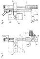
- FIG 1 is an overview of the device for contactless scanning a stack side edge S shown.
- a bow 2 is therein a blower 2 assigned.
- the blower 2 serves to fan out the sheets lying one on top of the other in the sheet stack 1 and is a short distance from the side edge S of the stack Sheet stack 1 arranged.
- the blower 2 is attached to a bracket 3 which around an axis 4 is pivotable.
- the holder 7 carries sensors 6.
- FIG. 2 shows the representation from FIG. 1 in a different view.
- the Blowers 2 can now see the air outlet openings.
- Art the attachment to the bracket 3 shown the axis 4 can be seen.
- the Axis 4 is shown as a thickened wave compared to FIG.
- a hole 5 can be seen, the inclusion of one to the side Setting suitable guide rod within the sheet feeder is used. On the guide rod is therefore the entire arrangement corresponding to one desired sheet format can be moved and adjusted.
- the Device using a clamping device on a corresponding shaft be clamped.
- the holder 7 is also shown in FIG.
- the holder 7 carries the two sensors 6.
- the two sensors 6 are present in accordance with FIG the plane of the fan 2 relatively close to the stack side edge S of the sheet stack 1.
- FIG. 1 A first variant is shown in FIG.
- the sensors 6.1 and 6.2 act as a distance meter according to the Optical triangulation method. They are the stack side edge S of the Sheet stack 1, its hatching here only the hint of the material paper serves and does not reflect the orientation of the sheets in different ways assigned.
- a tolerance range D is shown in the area of the stack side edge S. This tolerance range D gives the maximum allowed difference in the deviation of the Sheet stack 1 towards the sides as they arise from the specifications of Sheet feed to the sheet processing machine results.
- the Sensors 6.1 and 6.2 are set differently in their scanning length. The set imaging focus for the sensor 6.1 corresponds to the distance Z from the sensor level of the sensor 6.1.
- the set focus for the sensor 6.2 corresponds to the distance Y from the sensor plane of the sensor 6.2.
- the difference between the distances Z and Y results in that for the sheet processing machine allowable tolerance range D for the deviation of the Stack side edge S of the sheet stack 1. Due to the different adjustment. the sensors 6.1, 6.2 is the tolerance range D in the simplest way for different needs depending on paper quality or requirements at sheet processing machine adjustable.
- FIG. Another variant is shown in FIG.
- sensors 6.1 and 6.2 attached to the holder 7.
- Working accuracy is here from a standard distance of Measurement level from the sensor level. Therefore both sensors are 6.1 and 6.2 set to a fixed and equal measuring distance X.
- Tolerance range D for the deviation of the stack side edge S of the sheet stack 1 To be able to detect the one sensor 6.1 at a different altitude on the Holder 7 mounted as the second sensor 6.2.
- the sensor 6.1 with a Fit piece 8 underlaid.
- the senor 6.1 could in the direction of Stack side edge S slidably attached to the holder 7 and so on different distances from the sensor 6.2 can be set.
- a similar one physical behavior, such as aging or environmental influences is. The measuring accuracy of the entire arrangement is thus accordingly overall unaffected.
- each of the two sensors 6.1, 6.2 will detect one of the tolerance limits of the stack side edge S away from the sheet stack 1 or towards the sheet stack 1.
- the sensor 6.1 scans the tolerance limit inside the stack and the sensor 6.2 scans the tolerance limit outside the stack.
- the stack side edge S moves within the tolerance range D, none of the sensors 6.1, 6.2 responds.
- the scanned stack side edge S is then within the specified tolerance.
- one of the sensors 6.1, 6.2 responds and causes the adjustment device for the sheet stack 1 to shift in the opposite direction. With the slow lifting movement of the sheet stack 1, a rapid and extremely precise tracking of the stack side edge S of the sheet stack 1 is possible.
- the variants shown show a very simple solution for the execution of contactless scanning of stack side edges S.
- the connection of the Sensors with a possibly automatic actuator for the wind instruments automates the positioning of different sheet formats and This further facilitates the adjustment work.
- the adjustment of the sensors 6.1, 6.2 is carried out once and allows the Tolerance width D of the stack side edge S is permanent, simple and safe non-contact stack edge scanning.
Landscapes
- Controlling Sheets Or Webs (AREA)
- Folding Of Thin Sheet-Like Materials, Special Discharging Devices, And Others (AREA)
- Silver Salt Photography Or Processing Solution Therefor (AREA)
- Electroluminescent Light Sources (AREA)
- Sheets, Magazines, And Separation Thereof (AREA)
Description
- Figur 1
- eine Ansicht einer erfindungsgemäßen Vorrichtung,
- Figur 2
- eine zweite Ansicht der erfindungsgemäßen Vorrichtung,
- Figur 3
- eine schematische Darstellung einer ersten Wirkungsweise und
- Figur 4
- eine schematische Darstellung einer zweiten Wirkungsweise.
Je nach abzutastender Stapelseitenkante S wird jeder der beiden Sensoren 6.1, 6.2 eine der Toleranzgrenzen der Stapelseitenkante S vom Bogenstapel 1 weg oder zum Bogenstapel 1 hin erfassen. In den Figuren 3 und 4 tastet jeweils der Sensor 6.1 die stapelinnere Toleranzgrenze ab und der Sensor 6.2 tastet die stapeläußere Toleranzgrenze ab. Bei Bewegung der Stapelseitenkante S innerhalb der Toleranzbreite D spricht keiner der Sensoren 6.1, 6.2 an. Die abgetastete Stapelseitenkante S liegt dann also innerhalb der vorgegebenen Toleranz. Bei Verlagerung der Stapelseitenkante S spricht einer der Sensoren 6.1, 6.2 an und veranlaßt die Verstelleinrichtung für den Bogenstapel 1 zur Verschiebung in der Gegenrichtung. Bei der langsamen Hubbewegung des Bogenstapels 1 ist so eine schnelle und äußerst genaue Nachführung der Stapelseitenkante S des Bogenstapels 1 möglich.
Claims (5)
- Vorrichtung zur berührungslosen Abtastung einer Stapelseitenkante eines Bogenstapels in einem Bogenanleger einer bogenverarbeitenden Maschine mit wenigstens einem nach dem Prinzip der optischen Triangulation wirkenden Sensor zur Erfassung der Lage der Stapelseitenkante in Bezug auf einen vorgebbaren Toleranzbereich,
dadurch gekennzeichnet, daß parallel zueinander zwei Sensoren (6.1, 6.2) vorgesehen sind, die auf zwei unterschiedliche Abtastabstände bezüglich der gleichen Stapelseitenkante (S) des Bogenstapels (1) einstellbar sind, wobei der der. Toleranzbereich für die Lage der Stapelseitenkante (S) als Toleranzbreite (D) durch die Entfernung des Abtastabstandes des einen Sensors (6.1), der zur Innenseite des Bogenstapels (1) hin orientiert ist, von dem Abtastabstand des anderen Sensors (6.2), der vom Bogenstapel (1) weg orientiert ist, gebildet wird. - Vorrichtung nach Anspruch 1,
dadurch gekennzeichnet, daß die Sensoren (6.1, 6.2) mit ihren Sensorebenen in einer gemeinsamen Ebene angeordnet sind und daß die Abtastabstände der Sensoren (6.1, 6.2) auf eine entsprechend der Toleranzbreite (D) unterschiedliche Größe einstellbar sind. - Vorrichtung nach Anspruch 1,
dadurch gekennzeichnet, daß die Sensoren (6.1, 6.2) mit ihren Sensorebenen in zwei verschiedenen Ebenen angeordnet sind, deren Abstand entsprechend der Toleranzbreite (D) entspricht, und daß die Abtastabstände der Sensoren (6.1, 6.2) auf eine untereinander gleiche Größe einstellbar sind. - Vorrichtung nach Anspruch 3,
dadurch gekennzeichnet, daß der eine Sensor (6.1) gegenüber dem anderen Sensor (6.2) relativ zur Stapelseitenkante (S) des Bogenstapels (1) verschiebbar angeordnet ist. - Vorrichtung nach Anspruch 3,
dadurch gekennzeichnet, daß der eine Sensor (6.1) gegenüber dem anderen Sensor (6.2) relativ zur Stapelseitenkante (S) des Bogenstapels (1) versetzt und mit festem Abstand angeordnet ist.
Applications Claiming Priority (2)
| Application Number | Priority Date | Filing Date | Title |
|---|---|---|---|
| DE19802408 | 1998-01-23 | ||
| DE19802408A DE19802408A1 (de) | 1998-01-23 | 1998-01-23 | Berührungslose Stapelkantenabtastung |
Publications (2)
| Publication Number | Publication Date |
|---|---|
| EP0931746A1 EP0931746A1 (de) | 1999-07-28 |
| EP0931746B1 true EP0931746B1 (de) | 2002-05-08 |
Family
ID=7855389
Family Applications (1)
| Application Number | Title | Priority Date | Filing Date |
|---|---|---|---|
| EP98124671A Expired - Lifetime EP0931746B1 (de) | 1998-01-23 | 1998-12-24 | Berührungslose Stapelkantenabtastung |
Country Status (3)
| Country | Link |
|---|---|
| EP (1) | EP0931746B1 (de) |
| AT (1) | ATE217293T1 (de) |
| DE (2) | DE19802408A1 (de) |
Cited By (1)
| Publication number | Priority date | Publication date | Assignee | Title |
|---|---|---|---|---|
| EP1970338A2 (de) | 2007-03-13 | 2008-09-17 | manroland AG | Verfahren und Vorrichtung zur berührungslosen Stapelerfassung |
Family Cites Families (2)
| Publication number | Priority date | Publication date | Assignee | Title |
|---|---|---|---|---|
| DD211539A1 (de) * | 1982-11-18 | 1984-07-18 | Polygraph Leipzig | Vorschubeinrichtung zum kontinuierlichen foerdern eines bogenstapels |
| DE4129702C2 (de) * | 1991-03-25 | 1994-08-11 | Heidelberger Druckmasch Ag | Verfahren und Vorrichtung zur optischen Messung der Differenzentfernung zwischen zwei Objekten |
-
1998
- 1998-01-23 DE DE19802408A patent/DE19802408A1/de not_active Withdrawn
- 1998-12-24 EP EP98124671A patent/EP0931746B1/de not_active Expired - Lifetime
- 1998-12-24 DE DE59804043T patent/DE59804043D1/de not_active Expired - Lifetime
- 1998-12-24 AT AT98124671T patent/ATE217293T1/de not_active IP Right Cessation
Cited By (2)
| Publication number | Priority date | Publication date | Assignee | Title |
|---|---|---|---|---|
| EP1970338A2 (de) | 2007-03-13 | 2008-09-17 | manroland AG | Verfahren und Vorrichtung zur berührungslosen Stapelerfassung |
| DE102007011928A1 (de) | 2007-03-13 | 2008-09-18 | Man Roland Druckmaschinen Ag | Verfahren und Vorrichtung zur berührungslosen Stapelerfassung |
Also Published As
| Publication number | Publication date |
|---|---|
| DE59804043D1 (de) | 2002-06-13 |
| DE19802408A1 (de) | 1999-07-29 |
| ATE217293T1 (de) | 2002-05-15 |
| EP0931746A1 (de) | 1999-07-28 |
Similar Documents
| Publication | Publication Date | Title |
|---|---|---|
| DE3713279C2 (de) | Verfahren zum Erfassen von Dimensionsfehlern und/oder dem Verzug von Papierbahnen oder Formatpapieren | |
| EP0295433B1 (de) | Registermesssystem, wie es im Offsetbereich zur Kontrolle der Lage der Druckplatten Anwendung findet | |
| EP0596330B1 (de) | Anordnung zum messtechnischen Erfassen von Lastpendelungen bei Kranen | |
| DE3726704C2 (de) | ||
| EP0114914B1 (de) | Vorrichtung zum Ermitteln und Auswerten von Farbmessfeldern auf einem Druckbogen | |
| DE3789847T2 (de) | Vorrichtung zum Zuführen und Überwachen von Streifen. | |
| DD201435A1 (de) | Verfahren und einrichtung zur bestimmung von falzabweichungen | |
| DE10127249A1 (de) | Verfahren zum Ermitteln einer Position eines Druckbildes und Überwachungseinrichtung für eine Druckmaschine | |
| DE69524288T2 (de) | Apparat und Skala zum Messen einer Dimension eines Objektes | |
| DE19909518A1 (de) | Verfahren und Vorrichtung zur Erfassung der Lage von gestapeltem Material | |
| DE102020118254A1 (de) | Leitstand einer Bogenbearbeitungsmaschine und Verfahren zum Ausrichten eines Bogens auf einer Auflagefläche | |
| EP0931746B1 (de) | Berührungslose Stapelkantenabtastung | |
| EP0131109A2 (de) | Vorrichting zum Ermitteln und Auswerten von Farbmessfeldern auf einem auf einem Messtisch liegenden Druckbogen mit einem Densitometer | |
| DE10135011A1 (de) | Vorrichtung zum Zuführen von Bogen und Verfahren zum Steuern der Höhenposition von gestapelten Bogen | |
| DE3711646C2 (de) | Vorrichtung zum Ermitteln der Lage einer Kerblinie auf der Oberfläche eines Werkstückes und zum Einstellen des Werkstückes in eine Biegeposition | |
| EP1936945B1 (de) | Abtastvorrichtung mit elektronischer Abstandsregelung und ohne Abstandsmessfühler | |
| EP4514562B1 (de) | Verfahren zum ermitteln von, insbesondere statischen, geometriefehlern einer lasermaschine zum schneiden, gravieren, markieren und/oder beschriften eines werkstückes und ein verfahren zum ermitteln der lage bzw. position des mittelpunkts eines detektors am detektorelement sowie kalibrier-segment und lasermaschine hierfür | |
| EP1980516B1 (de) | Messverfahren und Vorrichtung zur Bestimmung der Lage von Materialbahnen | |
| EP0894755B1 (de) | Ausrichtvorrichtung für einen automatischen Stapelwechsler | |
| DE20216042U1 (de) | Vorrichtung zur Erfassung der Kantenpositionen von Bögen in einer bogenverarbeitenden Maschine | |
| EP0931740B1 (de) | Vorrichtung zum Abtaten einer Stapelkante eines Bogenstapels in einem Bogenanleger | |
| DE10028523B4 (de) | Vorrichtung zum Messen der Höhe eines Bogenstapels unter Verwendung eines im Reflexbetrieb arbeitenden Strahlungsdetektors | |
| EP1207026B1 (de) | Justiereinrichtung sowie Verfahren zur Voreinstellung einer Schneideinrichtung | |
| DE102012216325B4 (de) | Bogenverarbeitende Maschine mit einem Anleger | |
| DE3907583C2 (de) |
Legal Events
| Date | Code | Title | Description |
|---|---|---|---|
| PUAI | Public reference made under article 153(3) epc to a published international application that has entered the european phase |
Free format text: ORIGINAL CODE: 0009012 |
|
| AK | Designated contracting states |
Kind code of ref document: A1 Designated state(s): AT DE FR GB IT |
|
| AX | Request for extension of the european patent |
Free format text: AL;LT;LV;MK;RO;SI |
|
| 17P | Request for examination filed |
Effective date: 19990609 |
|
| AKX | Designation fees paid |
Free format text: AT DE FR GB IT |
|
| GRAG | Despatch of communication of intention to grant |
Free format text: ORIGINAL CODE: EPIDOS AGRA |
|
| GRAG | Despatch of communication of intention to grant |
Free format text: ORIGINAL CODE: EPIDOS AGRA |
|
| GRAH | Despatch of communication of intention to grant a patent |
Free format text: ORIGINAL CODE: EPIDOS IGRA |
|
| GRAH | Despatch of communication of intention to grant a patent |
Free format text: ORIGINAL CODE: EPIDOS IGRA |
|
| 17Q | First examination report despatched |
Effective date: 20010724 |
|
| REG | Reference to a national code |
Ref country code: GB Ref legal event code: IF02 |
|
| GRAA | (expected) grant |
Free format text: ORIGINAL CODE: 0009210 |
|
| AK | Designated contracting states |
Kind code of ref document: B1 Designated state(s): AT DE FR GB IT |
|
| REF | Corresponds to: |
Ref document number: 217293 Country of ref document: AT Date of ref document: 20020515 Kind code of ref document: T |
|
| GBT | Gb: translation of ep patent filed (gb section 77(6)(a)/1977) |
Effective date: 20020510 |
|
| REF | Corresponds to: |
Ref document number: 59804043 Country of ref document: DE Date of ref document: 20020613 |
|
| ET | Fr: translation filed | ||
| PGFP | Annual fee paid to national office [announced via postgrant information from national office to epo] |
Ref country code: GB Payment date: 20021128 Year of fee payment: 5 |
|
| PGFP | Annual fee paid to national office [announced via postgrant information from national office to epo] |
Ref country code: FR Payment date: 20021206 Year of fee payment: 5 |
|
| PLBQ | Unpublished change to opponent data |
Free format text: ORIGINAL CODE: EPIDOS OPPO |
|
| PLAV | Examination of admissibility of opposition |
Free format text: ORIGINAL CODE: EPIDOS OPEX |
|
| PLBI | Opposition filed |
Free format text: ORIGINAL CODE: 0009260 |
|
| PLAV | Examination of admissibility of opposition |
Free format text: ORIGINAL CODE: EPIDOS OPEX |
|
| 26 | Opposition filed |
Opponent name: KBA KOENIG & BAUER AG Effective date: 20030114 |
|
| PLBF | Reply of patent proprietor to notice(s) of opposition |
Free format text: ORIGINAL CODE: EPIDOS OBSO |
|
| PLBF | Reply of patent proprietor to notice(s) of opposition |
Free format text: ORIGINAL CODE: EPIDOS OBSO |
|
| PLCK | Communication despatched that opposition was rejected |
Free format text: ORIGINAL CODE: EPIDOSNREJ1 |
|
| PLBN | Opposition rejected |
Free format text: ORIGINAL CODE: 0009273 |
|
| STAA | Information on the status of an ep patent application or granted ep patent |
Free format text: STATUS: OPPOSITION REJECTED |
|
| PG25 | Lapsed in a contracting state [announced via postgrant information from national office to epo] |
Ref country code: GB Free format text: LAPSE BECAUSE OF NON-PAYMENT OF DUE FEES Effective date: 20031224 |
|
| 27O | Opposition rejected |
Effective date: 20030815 |
|
| GBPC | Gb: european patent ceased through non-payment of renewal fee |
Effective date: 20031224 |
|
| PG25 | Lapsed in a contracting state [announced via postgrant information from national office to epo] |
Ref country code: FR Free format text: LAPSE BECAUSE OF NON-PAYMENT OF DUE FEES Effective date: 20040831 |
|
| REG | Reference to a national code |
Ref country code: FR Ref legal event code: ST |
|
| PG25 | Lapsed in a contracting state [announced via postgrant information from national office to epo] |
Ref country code: IT Free format text: LAPSE BECAUSE OF NON-PAYMENT OF DUE FEES Effective date: 20051224 |
|
| PGFP | Annual fee paid to national office [announced via postgrant information from national office to epo] |
Ref country code: AT Payment date: 20091217 Year of fee payment: 12 |
|
| PGFP | Annual fee paid to national office [announced via postgrant information from national office to epo] |
Ref country code: DE Payment date: 20091222 Year of fee payment: 12 |
|
| PG25 | Lapsed in a contracting state [announced via postgrant information from national office to epo] |
Ref country code: AT Free format text: LAPSE BECAUSE OF NON-PAYMENT OF DUE FEES Effective date: 20101224 |
|
| PG25 | Lapsed in a contracting state [announced via postgrant information from national office to epo] |
Ref country code: DE Free format text: LAPSE BECAUSE OF NON-PAYMENT OF DUE FEES Effective date: 20110701 |
|
| REG | Reference to a national code |
Ref country code: DE Ref legal event code: R119 Ref document number: 59804043 Country of ref document: DE Effective date: 20110701 |