EP0931700B1 - Vorrichtung zum Verschwenken und Stabilisieren eines Aussenrückblickspiegel - Google Patents
Vorrichtung zum Verschwenken und Stabilisieren eines Aussenrückblickspiegel Download PDFInfo
- Publication number
- EP0931700B1 EP0931700B1 EP99300460A EP99300460A EP0931700B1 EP 0931700 B1 EP0931700 B1 EP 0931700B1 EP 99300460 A EP99300460 A EP 99300460A EP 99300460 A EP99300460 A EP 99300460A EP 0931700 B1 EP0931700 B1 EP 0931700B1
- Authority
- EP
- European Patent Office
- Prior art keywords
- casing
- base
- locking
- mirror
- stabilization
- Prior art date
- Legal status (The legal status is an assumption and is not a legal conclusion. Google has not performed a legal analysis and makes no representation as to the accuracy of the status listed.)
- Expired - Lifetime
Links
Images



Classifications
-
- B—PERFORMING OPERATIONS; TRANSPORTING
- B60—VEHICLES IN GENERAL
- B60R—VEHICLES, VEHICLE FITTINGS, OR VEHICLE PARTS, NOT OTHERWISE PROVIDED FOR
- B60R1/00—Optical viewing arrangements; Real-time viewing arrangements for drivers or passengers using optical image capturing systems, e.g. cameras or video systems specially adapted for use in or on vehicles
- B60R1/02—Rear-view mirror arrangements
- B60R1/06—Rear-view mirror arrangements mounted on vehicle exterior
- B60R1/076—Rear-view mirror arrangements mounted on vehicle exterior yieldable to excessive external force and provided with an indexed use position
Definitions
- the present invention relates to a device or mechanism for tilting and stabilization of an external rear-view mirror, pertaining to the field of automobile parts and which was developed to overcome problems associated with conventional similar devices.
- a mechanism according to the preamble of claim 1 is known from DE 8711 959U.
- External rear-view mirrors for automotive vehicles being comprised essentially of a mirror plate; a mechanism for adjusting the position of the mirror plate by direct actuation of the mirror or via a mechanical lever or through an automatic button provided inside the vehicle; a casing which houses the plate and the adjustment mechanism; a base on which the casing is mounted and which is mounted on the side of the vehicle; and a mechanism for tilting of the casing with relation to the base.
- These known mirrors also incorporate a safety device intended to comply with the legal requirements.
- This safety device maintains the casing set in the position of use even if subjected to the typical vibrations of the movement of the vehicle and/or to the reaction forces of the air displacement acting on the casing and/or to an impact force on the casing, until certain safety limits, when the casing collides with an obstacle, and also allows the casing to tilt when the impact force surpasses a predetermined limit.
- This tilting mechanism with a safety device might have many constructive solutions, as disclosed in Brazilian Utility Model Application Nos. MU 7201917 and MU 7400425 and Brazilian Patent Application No. PI 9301058 of the same applicant.
- the above-mentioned utility models show mechanisms in which the connection between the casing and the base is made through helical springs, selected to maintain the casing in the position of use and to allow the same to tilt with relation to the base when subjected to impact above a predetermined limit.
- This detent system meets the legal safety requirements and specifications and is of great usefulness to the user, in so far as, in places with a reduced space of parking or to prevent an impact that might damage the mirror, the mirror can be tilted to an abutted position against the side of the vehicle and in this way avoids the above-mentioned problem.
- this system being an advance with respect to the above-mentioned ones, it has the problem of being relatively more complex and has a production process that is also relatively more complicated and expensive than the previous systems.
- an object of the present invention is to provide a mechanism for tilting and stabilization for a rear-view mirror that has a simple construction that can be compared with those of the utility models above mentioned and that at the same time can provide the detent function of the above mentioned patent.
- Another object of the present invention is to provide a mirror that has a mechanism for tilting and a detent device of a simpler construction and manufacture than the above mentioned mechanisms and other known ones.
- Another object of the present invention is that it is capable of adequately complying with the safety requirements and legislation.
- Another object of the present invention is to provide the above advantages without complicating or burdening the mirror and the productive process of the mirror.
- the present invention consists in a mechanism for tilting and stabilization of an external rear-view mirror, said mirror comprising a mirror plate, a casing housing the mirror plate, and a base which has the casing mounted on it and is capable of being mounted on a side of an automotive vehicle, said mechanism being arranged to tilt the casing with respect to the base and provide stabilization of the casing in respective positions of use and tilted, the mechanism including a device for stabilization of the casing in the respective positions of use and tilted comprising an element projecting from the front of the base directed to the extremity of the position of the casing, and an element provided on the extremity of the casing directed to the base, said elements cooperating with each other in locking of the casing in the position of use or blocking in the tilted position and remaining disposed in planes that are at least oblique with relation to a geometric axis, characterized in that the mechanism includes:-
- the mechanism of tilting and stabilization is part of an external rear-view mirror for automotive vehicles.
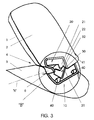
- the mirror essentially comprises a mirror plate 1; a mechanism (not shown) of adjustment of the position of the mirror plate 1, activated by the direct actuation thereof or via an internal mechanical lever or automatic button of the vehicle; a casing 2 which houses the plate 1 and adjustment mechanism; a base 3 on which the casing 2 is mounted and which is intended to be mounted on the side of an automotive vehicle; and a mechanism 4 for tilting of the casing 2, containing the plate 1 and adjustment mechanism, with relation to the base 3 and of stabilization of the casing 2 in the position of use (orthogonal with relation to the side of the vehicle). and tilted (abutted against the side of the vehicle).
- the casing 2 and base 3 are made from thermoplastics.
- the mechanism 4 of tilting and stabilization essentially comprises:
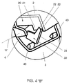
- the flange 30 of the base 3 has at least one surface 31 coplanar with respect to the respective surface 21 of the casing 2, both constituting locking surfaces by interference under pressure of the casing 2 in the base 3 in the position of use of the mirror (orthogonal to the side of the vehicle) and selected to provide a sufficient locking to support the vibrations and the reaction force of the displacement of the air on the casing 2 in the position of use during movement of the vehicle, as well as to support any impact force on the casing in the position of use up to a certain predetermined limit and to release the casing 2 to tilt when the impact force exceeds the predetermined limit.
- the flange 30 of the base 3 has at least one bumper or abutment surface 32, disposed at an angle with respect to the locking surface by interference 31 and that is disposed in the trajectory of the corresponding bumper or abutment surface 22 of the element 20 of the casing 2, during the unlocking of the surfaces 21 and 31 in the movement of the casing 2 around the "X" axis from the tilted position to the one of use.
- Both abutment surfaces 32 and 22 constitute blocking surfaces of the casing 2 in the tilted position (abutted against the side of the vehicle) and are chosen to provide a sufficient blocking to bear the force that acts on the casing 2 and in the sense of returning the same to the position of use, up to a certain predetermined limit.
- the abutment surface 32 of the flange 30 of the base 3 and the abutment surface 22 of the element 20 of the casing 2 have profiles and/or disposition with respect to each other and disposition with respect to the "X" geometric axis of point of support of the casing so as to form means for unlocking of the casing 2 from the tilted position, which are actuated whenever a force above the predetermined limit acts on the casing, in the sense of returning-the same to the position of use and effecting the sliding of the abutment surfaces 22 and 32 with respect to each other and in the sense of re-engaging the interference locking surfaces 21, 31 under pressure.
- both flange 30 and element 20, or at least the flange 30, are presented slightly bent due to the locking pressure of the connection surface by interference 21 of the flange 30.
- Such locking pressure which is helped, if needed, by the positioning members 40, 41 is sufficient to withstand the vibrations to which the mirror assembly is subjected to during movement of the vehicle, the reaction force of the air displacement which acts on the casing 2 during movement of the vehicle and which tends to release the casing from the position of use, and the force, up to a predetermined limit set by legislation, imparted by impact on the casing 2 during movement of the vehicle, such as when the mirror collides against a passer-by or other obstacles, thus protecting the integrity of the assembly and of the mirror itself.
- the abutment surface 22 of the element 20 causes pressure over the abutment surface 32 of the flange 30 of the base 3, but there is no unlocking of the casing 2 from the tilted position.
- the user presses the front of the casing 2 in the tilted position with a force above the predetermined limit, by which the abutment surface 22 of the element 20 presses over the abutment surface 32 of the flange 30 of the base 3 and there is a bending of the flange 30 and the element 20, or at least of the flange 30, and a consequent sliding between the abutment surfaces 22 and 32, in the sense of restoring the interference locking surfaces 21 and 31 coplanar.
- the tilting device of the present invention solves the problem of conventional similar devices in that it presents an extremely simple construction and manufacture.
- flange 30 and the corresponding elements 20 for locking by interference may be provided, as well as positioning members 40,41.
- Such flanges 30 and element 20 and positioning members 40,41 may have any configuration and dimensions specific to each case, so as to ensure the adequate locking and blocking in accordance with the invention.
- interference locking surfaces 21 and 31 of the element 20 and flange 30 may have profiles and/or relative positions and/or any superficial finishing that ensures the functioning of the same in accordance with the invention.
- the abutment surfaces 22 and 32 of the element 20 and flange 30 may have profiles, relative positions and any superficial finishing that allow them to work in accordance with the invention.
- the abutment surface 22 might be formed by a "V" cut made in the extremity of the flange 20 and the abutment surface 32 might be formed by a corresponding tooth provided in the flange 30 or vice versa. Both cut and tooth may be disposed in a way so as to define smooth surfaces, located at an angle with respect to the interference locking surfaces 21 and 31 and funnel-shaped in their direction to the opposed surfaces to the mentioned surfaces 21 and 31.
- funnel-shapings in the direction substantially parallel to the "X" geometric axis of point of support of the casing 2 in the base 3 are arranged in such a way that when the casing 2 is displaced from the tilted position to the position of use, the force that is applied to the same can be decomposed into the component of tilting of the casing 2 and the component of the relative sliding of the abutment surfaces 22 and 32.
- Logically other solutions might be given.
Landscapes
- Engineering & Computer Science (AREA)
- Multimedia (AREA)
- Mechanical Engineering (AREA)
- Rear-View Mirror Devices That Are Mounted On The Exterior Of The Vehicle (AREA)
Claims (10)
- Vorrichtung zum Kippen und Stabilisieren eines Außenrückspiegels, wobei der Spiegel eine Spiegelplatte (1), ein Gehäuse (2) in dem die Spiegelplatte (1) untergebracht ist, und eine Basis (3) umfasst, an der das Gehäuse (2) befestigt ist und die sich eignet, um an einer Seite eines Kraftfahrzeugs befestigt zu werden, wobei die Vorrichtung (4) dazu eingerichtet ist, das Gehäuse (2) bezüglich der Basis (3) zu kippen und eine Stabilisierung des Gehäuses (2) in Stellungen des Gebrauchs bzw. in einer gekippten Stellung vorzusehen, wobei die Vorrichtung (4) eine Einrichtung (10) einschließt, die dazu dient, das Gehäuse (2) in der Stellung des Gebrauchs bzw. in der gekippten Stellung zu stabilisieren, die ein Element (30), das aus der Vorderseite der Basis (3) in Richtung des äußersten Endes der Stellung des Gehäuses (2) weist, und ein Element (20) umfasst, das, auf die Basis (3) gerichtet, an dem äußersten Ende des Gehäuses (2) vorgesehen ist, wobei die Elemente (20,30) geeignet zusammenwirken, um das Gehäuse (2) in der Gebrauchsstellung zu verriegeln oder in der gekippten Stellung festzuhalten, und in Ebenen angeordnet bleiben, die gegenüber einer geometrischen Achse (X) zumindest schiefwinkelig sind,
dadurch gekennzeichnet, dass die Vorrichtung (4) fernerGelenkmittel (6) aufweist, die dazu dienen, eine Bewegung des Gehäuses (2) bezüglich der Basis (3) um die geometrische Achse (X) zu ermöglichen,und das Element (30) eine nachgiebige Struktur aufweist. - Vorrichtung nach Anspruch 1, wobei das Element (30) an der Basis (3) durch einen klemmenden/sperrenden Sitz einen Verriegelungsflansch bildet.
- Vorrichtung nach Anspruch 1 oder 2, wobei das Element (20) des Gehäuses (2) durch einen klemmenden/sperrenden Sitz einen nachgebenden Verriegelungsflansch darstellt.
- Vorrichtung nach Anspruch 1, 2 oder 3, wobei die Elemente (20,30) in Ebenen verbleiben, die senkrecht zu der geometrischen Achse (X) verlaufen.
- Vorrichtung nach einem der vorhergehenden Ansprüche, wobei die Elemente (20,30) aus dem gleichen Werkstoff und mit der Basis (3) bzw. dem Gehäuse (2) einstückig hergestellt sind.
- Vorrichtung nach einem der vorhergehenden Ansprüche, die ein oder mehrere Positionierungselemente (4) und entsprechende Anschlussflächen (41) aufweist, die einstückig an dem Gehäuse (2) und/oder der Basis (3) ausgebildet sind und dazu eingerichtet sind, um den verriegelnden Druck zwischen den Elementen (20,30) sicherzustellen.
- Vorrichtung nach einem der vorhergehenden Ansprüche, wobei die Elemente (20,30) entsprechende koplanare Verriegelungsflächen (21,31) aufweisen, die in der Gebrauchsstellung des Spiegels die Verriegelung des Gehäuses (2) mit der Basis (3) durch das unter Druck bestehende Klemmen herstellen und eine ausreichende Verriegelung vorsehen, um den Schwingungen und der Reaktionskraft standzuhalten, die in der Gebrauchsstellung während der Bewegung des Fahrzeugs aufgrund der Verdrängung der Luft auf das Gehäuse (2) wirkt, sowie in der Gebrauchsstellung bis zu einem gewissen vorgegebenen Grenzwert jeder auf das Gehäuse wirkenden Aufprallkraft zu widerstehen, und das Gehäuse (2) für ein Kippen freizugeben, wenn die Aufprallkraft den vorgegebenen Grenzwert überschreitet.
- Vorrichtung nach Anspruch 7, wobei das Element (30) der Basis (3) wenigstens eine Anlagefläche (32) aufweist, die unter einem Winkel zu der Verriegelungsfläche (31) ausgebildet ist und die in der Bahn einer entsprechenden Anlagefläche (22) des Elements (20) des Gehäuses (2) angeordnet ist, die diese während des Entriegelns der Verriegelungsflächen (21) und (31) im Verlauf der Bewegung des Gehäuses (2) um die geometrische Achse (X) aus der gekippten Stellung in die Gebrauchsstellung durchläuft, wobei die beiden Anlageflächen (32) und (22) Sperrflächen des Gehäuses (2) in der gekippten Stellung bilden und geeignet eingerichtet sind, um eine ausreichende Sperrwirkung bereitzustellen, um bis zu einem vorgegebenen Grenzwert einer Kraft zu widerstehen, die auf das Gehäuse (2) in Richtung eines Zurückbewegens derselben in die Gebrauchsstellung wirkt.
- Vorrichtung nach Anspruch 8, wobei die Anlagefläche (32) des Elements (30) der Basis (3) und die Anlagefläche (22) des Elements (20) des Gehäuses (2) mit Profilen ausgebildet sind und/oder zueinander und gegenüber der geometrischen Achse (X) relative Neigungen aufweisen, die geeignet ausgewählt sind, um eine Freigabe des Gehäuses (2) aus der gekippten Stellung zu erreichen, wenn eine den vorgegebenen Grenzwert überschreitende Kraft auf das Gehäuse (2) in Richtung der Rückkehr des Gehäuses (2) in die Gebrauchsstellung wirkt, und ein Gleiten der Anlageflächen (22) und (32) relativ zueinander im Hinblick darauf vorsieht, die Verriegelungsflächen (21,31) unter Druck wieder in eine koplanare Stellung und in einen Zustand des wieder in Eingriff gebrachten Klemmsitzes zu bringen.
- Außenrückspiegel für ein Kraftfahrzeug, der eine Spiegelplatte (1), ein Gehäuse (2) in dem die Spiegelplatte (1) untergebracht ist, und eine Basis (3), an der das Gehäuse (2) befestigt ist und die sich eignet, um an einer Seite eines Kraftfahrzeugs befestigt zu werden, und eine Vorrichtung (4) umfasst, die dazu dient, den Spiegel zu kippen und zu stabilisieren, nach einem der vorhergehenden Ansprüche.
Applications Claiming Priority (2)
| Application Number | Priority Date | Filing Date | Title |
|---|---|---|---|
| BR9802655 | 1998-01-22 | ||
| BR9802655-0A BR9802655A (pt) | 1998-01-22 | 1998-01-22 | Dispositivo de basculamento e estabilização de espelho retrovisor externo. |
Publications (3)
| Publication Number | Publication Date |
|---|---|
| EP0931700A2 EP0931700A2 (de) | 1999-07-28 |
| EP0931700A3 EP0931700A3 (de) | 2000-09-06 |
| EP0931700B1 true EP0931700B1 (de) | 2003-07-02 |
Family
ID=38282791
Family Applications (1)
| Application Number | Title | Priority Date | Filing Date |
|---|---|---|---|
| EP99300460A Expired - Lifetime EP0931700B1 (de) | 1998-01-22 | 1999-01-21 | Vorrichtung zum Verschwenken und Stabilisieren eines Aussenrückblickspiegel |
Country Status (7)
| Country | Link |
|---|---|
| US (1) | US5980051A (de) |
| EP (1) | EP0931700B1 (de) |
| AR (1) | AR017814A1 (de) |
| BR (1) | BR9802655A (de) |
| CA (1) | CA2259858C (de) |
| DE (1) | DE69909146T2 (de) |
| ES (1) | ES2197577T3 (de) |
Families Citing this family (1)
| Publication number | Priority date | Publication date | Assignee | Title |
|---|---|---|---|---|
| DE102004042260B4 (de) * | 2004-09-01 | 2010-08-05 | SMR Patents S.à.r.l. | Außenrückblickspiegel für Fahrzeuge, vorzugsweise für Kraftfahrzeuge |
Family Cites Families (10)
| Publication number | Priority date | Publication date | Assignee | Title |
|---|---|---|---|---|
| JPS61105248A (ja) * | 1984-10-29 | 1986-05-23 | Ichikoh Ind Ltd | 緩衝式ドアミラ− |
| JPS6264648A (ja) * | 1985-09-18 | 1987-03-23 | Ichikoh Ind Ltd | 自動車用ドアミラ− |
| DE8711959U1 (de) * | 1987-09-03 | 1987-12-23 | Hohe Kg, 6981 Collenberg | Außenspiegel für ein Fahrzeug mit einem Spiegelfuß und einem relativ zum Spiegelfuß aus einer Gebrauchslage nach vorne und hinten abklappbaren Spiegelgehäuse |
| DE8813505U1 (de) * | 1988-10-27 | 1989-03-23 | Hohe Kg, 6981 Collenberg | Abklappbarer Außenspiegel für Fahrzeuge |
| WO1991018758A1 (fr) * | 1990-05-29 | 1991-12-12 | Ichikoh Industries, Ltd. | Retroviseur a telecommande electrique |
| US5793543A (en) * | 1992-06-04 | 1998-08-11 | Kabushiki Kaisha Matsuyama Seisakusho | Mirror angle adjusting device for automotive rearview mirror assembly |
| BR7201917U (pt) * | 1992-11-17 | 1994-05-24 | Metagal Ind & Comercio | Disposiçao em espelho retrovisor externo |
| BR9301058A (pt) * | 1993-05-07 | 1994-11-29 | Metagal Ind & Comercio | Aperfeiçoamento em dispositivo para basculamento de espelho retrovisor externo para veículos |
| BR7400425U (pt) * | 1994-03-15 | 1995-10-17 | Metagal Ind & Comercio | Disposição em espelho retrovisor externo |
| US5838507A (en) * | 1996-12-19 | 1998-11-17 | Lowell Engineering Corporation | Mirror assembly with friction drive |
-
1998
- 1998-01-22 BR BR9802655-0A patent/BR9802655A/pt not_active IP Right Cessation
- 1998-12-07 AR ARP980106189A patent/AR017814A1/es unknown
- 1998-12-31 US US09/224,472 patent/US5980051A/en not_active Expired - Fee Related
-
1999
- 1999-01-21 EP EP99300460A patent/EP0931700B1/de not_active Expired - Lifetime
- 1999-01-21 DE DE69909146T patent/DE69909146T2/de not_active Expired - Lifetime
- 1999-01-21 ES ES99300460T patent/ES2197577T3/es not_active Expired - Lifetime
- 1999-01-22 CA CA002259858A patent/CA2259858C/en not_active Expired - Fee Related
Also Published As
| Publication number | Publication date |
|---|---|
| CA2259858A1 (en) | 1999-07-22 |
| DE69909146T2 (de) | 2004-04-15 |
| EP0931700A3 (de) | 2000-09-06 |
| CA2259858C (en) | 2007-06-19 |
| EP0931700A2 (de) | 1999-07-28 |
| AR017814A1 (es) | 2001-10-24 |
| ES2197577T3 (es) | 2004-01-01 |
| BR9802655A (pt) | 2000-04-25 |
| US5980051A (en) | 1999-11-09 |
| DE69909146D1 (de) | 2003-08-07 |
Similar Documents
| Publication | Publication Date | Title |
|---|---|---|
| EP0151642B1 (de) | Rückspiegel für fahrzeuge | |
| US5384660A (en) | Foldable outside rearview mirror | |
| US5377948A (en) | Breakaway rearview mirror mounting bracket | |
| EP2230131B1 (de) | Zusammenklappbare Rückspiegeleinheit für ein Fahrzeug | |
| MXPA00008855A (es) | Conjunto de montaje de espejo con dispositivo de tope. | |
| US4422724A (en) | Rear view mirror arrangement to be mounted on a vehicle door | |
| US6132050A (en) | Rearview mirror system for vehicles | |
| EP0757802B1 (de) | In rückwärtige gefaltete position bewegbare spiegelanordnung mit rückstellender federspannung | |
| EP1369301B1 (de) | Fahrzeugaussenspiegel | |
| US5871233A (en) | Steering device equipped with air bag | |
| US6637715B2 (en) | Vehicular exterior break-away mirror assembly | |
| EP1373019B1 (de) | Fahrzeugaussenspiegel mit selbstbelastungsdrehzapfen und endanschlag | |
| GB2315721A (en) | A vibration stabilised rearview mirror assembly | |
| MXPA00008856A (es) | Conjunto de montaje de espejo con ajuste biaxial. | |
| JP3064912B2 (ja) | 車両用ステアリングコラム | |
| EP3592607B1 (de) | Umschaltpaddel für anzeigespiegel | |
| US6672726B1 (en) | Extending and rotating rearview mirror assembly | |
| EP0931700B1 (de) | Vorrichtung zum Verschwenken und Stabilisieren eines Aussenrückblickspiegel | |
| US5088766A (en) | Steering system for vehicle | |
| JPH085358B2 (ja) | 安全ベルト収納器の製作方法 | |
| JP2788349B2 (ja) | 脱落バックミラー取付ブラケット | |
| JP3349082B2 (ja) | インナーミラーの回避構造 | |
| US4523736A (en) | Device for mounting a rearview mirror casing on a support member | |
| EP2026995A1 (de) | Sicherheitsanordnung und verfahren zur montage einer sicherheitsanordnung | |
| US7152986B2 (en) | Modular pivot arrangement |
Legal Events
| Date | Code | Title | Description |
|---|---|---|---|
| PUAI | Public reference made under article 153(3) epc to a published international application that has entered the european phase |
Free format text: ORIGINAL CODE: 0009012 |
|
| AK | Designated contracting states |
Kind code of ref document: A2 Designated state(s): DE ES FR GB IT |
|
| AX | Request for extension of the european patent |
Free format text: AL;LT;LV;MK;RO;SI |
|
| PUAL | Search report despatched |
Free format text: ORIGINAL CODE: 0009013 |
|
| AK | Designated contracting states |
Kind code of ref document: A3 Designated state(s): AT BE CH CY DE DK ES FI FR GB GR IE IT LI LU MC NL PT SE |
|
| AX | Request for extension of the european patent |
Free format text: AL;LT;LV;MK;RO;SI |
|
| 17P | Request for examination filed |
Effective date: 20010301 |
|
| AKX | Designation fees paid |
Free format text: DE ES FR GB IT |
|
| GRAH | Despatch of communication of intention to grant a patent |
Free format text: ORIGINAL CODE: EPIDOS IGRA |
|
| RIN1 | Information on inventor provided before grant (corrected) |
Inventor name: MILANI, PAULO ROBERTO, RUA ANNY 1000 AP.53 Inventor name: ANZE, FABIO KOITI, RUA LUCIO PAVAN 84 Inventor name: MORENO, RICARDO POVEDA, RUA DOS SABRIAS 351 |
|
| GRAH | Despatch of communication of intention to grant a patent |
Free format text: ORIGINAL CODE: EPIDOS IGRA |
|
| GRAA | (expected) grant |
Free format text: ORIGINAL CODE: 0009210 |
|
| AK | Designated contracting states |
Designated state(s): DE ES FR GB IT |
|
| REG | Reference to a national code |
Ref country code: GB Ref legal event code: FG4D |
|
| REF | Corresponds to: |
Ref document number: 69909146 Country of ref document: DE Date of ref document: 20030807 Kind code of ref document: P |
|
| REG | Reference to a national code |
Ref country code: ES Ref legal event code: FG2A Ref document number: 2197577 Country of ref document: ES Kind code of ref document: T3 |
|
| PLBE | No opposition filed within time limit |
Free format text: ORIGINAL CODE: 0009261 |
|
| STAA | Information on the status of an ep patent application or granted ep patent |
Free format text: STATUS: NO OPPOSITION FILED WITHIN TIME LIMIT |
|
| ET | Fr: translation filed | ||
| 26N | No opposition filed |
Effective date: 20040405 |
|
| PGFP | Annual fee paid to national office [announced via postgrant information from national office to epo] |
Ref country code: GB Payment date: 20131219 Year of fee payment: 16 |
|
| PGFP | Annual fee paid to national office [announced via postgrant information from national office to epo] |
Ref country code: DE Payment date: 20140123 Year of fee payment: 16 |
|
| PGFP | Annual fee paid to national office [announced via postgrant information from national office to epo] |
Ref country code: IT Payment date: 20140128 Year of fee payment: 16 Ref country code: FR Payment date: 20140124 Year of fee payment: 16 Ref country code: ES Payment date: 20140122 Year of fee payment: 16 |
|
| REG | Reference to a national code |
Ref country code: DE Ref legal event code: R119 Ref document number: 69909146 Country of ref document: DE |
|
| GBPC | Gb: european patent ceased through non-payment of renewal fee |
Effective date: 20150121 |
|
| PG25 | Lapsed in a contracting state [announced via postgrant information from national office to epo] |
Ref country code: GB Free format text: LAPSE BECAUSE OF NON-PAYMENT OF DUE FEES Effective date: 20150121 Ref country code: DE Free format text: LAPSE BECAUSE OF NON-PAYMENT OF DUE FEES Effective date: 20150801 |
|
| REG | Reference to a national code |
Ref country code: FR Ref legal event code: ST Effective date: 20150930 |
|
| PG25 | Lapsed in a contracting state [announced via postgrant information from national office to epo] |
Ref country code: FR Free format text: LAPSE BECAUSE OF NON-PAYMENT OF DUE FEES Effective date: 20150202 |
|
| PG25 | Lapsed in a contracting state [announced via postgrant information from national office to epo] |
Ref country code: IT Free format text: LAPSE BECAUSE OF NON-PAYMENT OF DUE FEES Effective date: 20150121 |
|
| REG | Reference to a national code |
Ref country code: ES Ref legal event code: FD2A Effective date: 20160226 |
|
| PG25 | Lapsed in a contracting state [announced via postgrant information from national office to epo] |
Ref country code: ES Free format text: LAPSE BECAUSE OF NON-PAYMENT OF DUE FEES Effective date: 20150122 |