EP0930093A2 - Vorrichtung zum Rühren eines Rührgutes sowie Anwendung der Rührvorrichtung - Google Patents
Vorrichtung zum Rühren eines Rührgutes sowie Anwendung der Rührvorrichtung Download PDFInfo
- Publication number
- EP0930093A2 EP0930093A2 EP99810014A EP99810014A EP0930093A2 EP 0930093 A2 EP0930093 A2 EP 0930093A2 EP 99810014 A EP99810014 A EP 99810014A EP 99810014 A EP99810014 A EP 99810014A EP 0930093 A2 EP0930093 A2 EP 0930093A2
- Authority
- EP
- European Patent Office
- Prior art keywords
- container
- sword
- stirring device
- stirring
- wall
- Prior art date
- Legal status (The legal status is an assumption and is not a legal conclusion. Google has not performed a legal analysis and makes no representation as to the accuracy of the status listed.)
- Withdrawn
Links
Images


Classifications
-
- B—PERFORMING OPERATIONS; TRANSPORTING
- B01—PHYSICAL OR CHEMICAL PROCESSES OR APPARATUS IN GENERAL
- B01F—MIXING, e.g. DISSOLVING, EMULSIFYING OR DISPERSING
- B01F27/00—Mixers with rotary stirring devices in fixed receptacles; Kneaders
- B01F27/05—Stirrers
- B01F27/11—Stirrers characterised by the configuration of the stirrers
- B01F27/112—Stirrers characterised by the configuration of the stirrers with arms, paddles, vanes or blades
- B01F27/1125—Stirrers characterised by the configuration of the stirrers with arms, paddles, vanes or blades with vanes or blades extending parallel or oblique to the stirrer axis
-
- B—PERFORMING OPERATIONS; TRANSPORTING
- B01—PHYSICAL OR CHEMICAL PROCESSES OR APPARATUS IN GENERAL
- B01F—MIXING, e.g. DISSOLVING, EMULSIFYING OR DISPERSING
- B01F27/00—Mixers with rotary stirring devices in fixed receptacles; Kneaders
- B01F27/80—Mixers with rotary stirring devices in fixed receptacles; Kneaders with stirrers rotating about a substantially vertical axis
- B01F27/82—Pan-type mixers, i.e. mixers in which the stirring elements move along the bottom of a pan-shaped receptacle
-
- B—PERFORMING OPERATIONS; TRANSPORTING
- B01—PHYSICAL OR CHEMICAL PROCESSES OR APPARATUS IN GENERAL
- B01F—MIXING, e.g. DISSOLVING, EMULSIFYING OR DISPERSING
- B01F27/00—Mixers with rotary stirring devices in fixed receptacles; Kneaders
- B01F27/80—Mixers with rotary stirring devices in fixed receptacles; Kneaders with stirrers rotating about a substantially vertical axis
- B01F27/90—Mixers with rotary stirring devices in fixed receptacles; Kneaders with stirrers rotating about a substantially vertical axis with paddles or arms
Definitions
- the present invention relates to the field of process engineering.
- she relates to a device for stirring a material to be stirred, comprising a container to hold the mix and one in the container around a vertical axis rotatably arranged stirring tool, which the material to be stirred during the stirring process transported up the inside wall of the container.
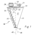
- a stirring device is e.g. as a screw cone mixer or dryer from the prior art Technology known and is from the company Hosokawa Micron B.V., Doetinchem, Holland, available on the market under the brand name Vrieco-Nauta.
- the known screw cone mixer 10 shown in FIG. 1, however, has several Disadvantages resulting from its constructive structure:
- Drive of the swivel arm 17 is a through the lid 14 of the container 11
- Shaft 18 guided via a gear unit arranged above the cover 14 19 is driven by a drive motor 20.
- the shaft 18 is as Hollow shaft executed.
- the swivel arm 17 is hollow. Inside the Shaft 18 and the swivel arm 17 is the drive train for the mixing screw 15 housed for driving a separate drive motor 21 on the gear unit 19 is flanged.
- the necessary redirection in the drive train from the shaft 18 to the swivel arm 17 and from the swivel arm 17 to the mixing screw 15 (in the reversing gear 16) is usually done via gears, the one Lubricate with oil or grease. Because the mix in most cases (e.g. in the pharmaceutical or food sector under no circumstances the lubricant may be contaminated, are on the seal of the inside Drive train for the mixing screw 15 the highest demands put. This leads to high expenditure in the design and manufacture of the Mixer. Nevertheless, there remains a not negligible residual risk that is not in can be tolerated in all applications.
- the Mixing screw 15 extends in a straight line and with a constant screw diameter along its axis of rotation 46. Since the screw as close as possible to the This has to be done along the inner wall of the container 11 necessarily a shape of the container with a straight wall contour, in particular in the form of a cone. Other container shapes, e.g. at the same Base area and height can enclose more volume than the pure cone are practically not used, which considerably increases the flexibility of the mixing principle restricted.
- the stirring tool along the inner wall of the container Includes blades which are rigid with at least one rotatable about the axis Swivel arm are connected.
- the essence of the invention is therefore that Rotary movement of the stirring tool around the container axis not only to be used to extend the stirring process over the entire container, but also at the same time by means of the blades the material to be stirred on the inner wall of the container to convey upwards.
- This eliminates the need for a separate drive train for an independent conveyor, as in the prior art by the Mixing screw is represented.
- the only remaining seal, namely the sealing of the shaft leading to the outside, on which the swivel arm is attached is simple and unproblematic.
- the shovels can be flexible in many different ways and adapted to different Container shapes can be arranged within the container.
- a first preferred embodiment of the stirring device is characterized in that the stirring tool at least one parallel to Inner wall of the container and with the at least one swivel arm rigidly connected sword, on which the blades laterally and in Longitudinal direction of the sword are arranged one above the other that the least a sword is spaced from the inner wall of the container, and that the blades are arranged between the sword and the inner wall of the container are.
- the design of the stirring tool as equipped with the blades Sword is particularly simple and stable and can be changed the sword shape can be flexibly adapted to different container geometries. If the sword is oriented parallel to the direction of rotation, it sets the rotary movement in Mixture comparatively little resistance. Number and distance of Blades lying one above the other are preferably selected such that the desired upward movement of the mix on the inside wall of the container results.
- the sword can be made from a flat profile made of coated (e.g. enamelled) steel or stainless steel to which the blades, which are also made of steel or stainless steel sheets, welded on or screwed or otherwise attached. But it is just as good it is also conceivable for the sword to be made in one piece together with the laterally formed blades train and manufacture as a forging or casting. Should that Mixed material not only be transported upwards on the container wall, but also it can also generate an additional mixing movement inwards be advantageous if according to a development of the embodiment on the side of the sword facing away from the inner wall of the container Inner blades are arranged. The inner blades also ensure that the sword is not one-sided due to the agitated material acting on the blades Bend is loaded.
- a second preferred embodiment of the stirring device according to the invention is characterized by the fact that several swords shoveled the axis is evenly distributed around and with associated swivel arms are rigidly connected, and that the swords on their by the swivel arms opposite ends are interconnected and a rigid cage form.
- the blades are formed as sheets at an angle to the axis.
- the angle of attack of the Sheet metal scoops are chosen so that the mix depends on the Speed of rotation of the sword or swords in the necessary upward movement is moved without excessively blocking the stirrer.
- the blades along the inside wall of the container are different the mixing screw of the well-known screw cone mixer over a longer one Line lie against the inner wall of the container, it is advantageous if according to a further embodiment of these blades on their facing the inner wall Edge have an edge contour that matches the contour of the inner wall is. This allows the distance between the entire blade length Minimize the bucket rim and inner wall so that, especially if the Stirring device is used as a dryer with heated container walls, the Contact of the agitated or mixed material with the container wall is particularly long and is intense.
- the shovel-carrying sword are specially designed and arranged to to influence the mixing or stirring process in a certain way.
- a sword is used which is curved coaxially to the axis, the effective cross section of the Sword in the direction of rotation and thus further reduce the resistance.
- the resistance, which the mix opposes to the rotation of the stirring tool, can also be reduced if, according to another embodiment, the in Edge of the sword lying in the direction of rotation is designed as a cutting edge.
- the sword is inclined relative to the direction of rotation, each result Different effects depending on the type of inclination: Is the inclination like this that the material to be stirred is transported outside by the rotating sword is the result of the result between the sword and the container wall
- Cross-sectional narrowing is a nozzle effect, which is particularly evident when stirring Liquids in a dryer or stirred tank is beneficial; the liquid is accelerated in the nozzle, which reduces the boundary layer and the heat transfer between liquid and (heated or cooled) container wall is increased. The flow breaks off behind the mixing tool and the heat transfer is increased again.
- the inclination is selected so that the material to be stirred is rotated by the Sword transported inwards results between the sword and Container wall a cross-sectional expansion.
- the container can be made by the inventive design of the stirring tool flexible in its form.
- the stirring device according to the invention is therefore characterized in that the container into an overhead cylindrical container part and one thereon downward-tapering container part is divided, and that the Stirring tool or the at least one sword divided into two sections which are adapted to the inner walls of the respective container part.
- the container into an overhead cylindrical container part and one thereon downward-tapering container part is divided, and that the Stirring tool or the at least one sword divided into two sections which are adapted to the inner walls of the respective container part.
- the stirring device is used as a mixer used.
- the Stirring device used as a contact dryer.
- the stirring device is used as a stirred tank.
- FIG. 2 shows a first preferred exemplary embodiment that is comparable to FIG. 1 a stirring device according to the invention in side view with cut Container shown.
- the stirring device 22 has a comparable to FIG. 1 simply conical container 23, the top through a lid 26 and the bottom through a container bottom 25 is limited.
- Inside the container 23 (in the interior 24) rotates a plurality of inclined ones arranged one above the other Scoops 28 (Fig. 4) which are attached to a sword 27 and over the Sword 27 rigidly connected to a swivel arm 29 rotatable about axis 47 are.
- the swivel arm 29 is via a shaft guided through the cover 26 30 and a gear unit 31 arranged above the cover 26 with a Drive motor 32 connected and is driven by the drive motor.
- the on the sword 27 seated blades 28 are close to the inner wall of the Container 23 guided around in a circle.
- the inclination of the blades 28 4 is chosen such that when the sword moves 27 in Direction of rotation (arrow in Fig. 4) the material to be stirred from the blades 28 on the inner wall of the container is successively transported upwards and in the central part of the container 23 sinks down again.
- the swivel arm 29 can for example be designed as a tube.
- a sword 27 is preferred a flat profile (e.g. made of stainless steel) is used, the thickness of which is large enough is grown to the mechanical loads during the stirring process be small enough to avoid unnecessary resistance when moving through to cause the mix.
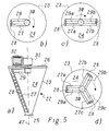
- a further stabilization and improvement of the synchronism can be achieved if three (or more) swords 27a, b, c on corresponding swivel arms 29a, b, c can be arranged in a star shape (Fig. 5 (d)). Because with each additional Sword also increases the number of blades 28 and thus the stirring power the mixing time (mixing time, Drying time). The geometry of the sword arrangement for one or two and three swords can be seen in Figs. 5 (b) - (c).
- Swivel arms 29 and 29a, b, c also one in the center of the circle with the shaft 30 connected circular disc can be used on which the swords 27th and 27a, b, c are attached.
- the blades 28 are preferred according to FIG. 4 formed as a simple, flat sheet metal parts, which are welded to the sword 27 or screwed on.
- the blades 28 can also be curved in themselves or be rotated about an axis, as is the case, for example, with turbine blades the case is.
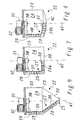
- the swords 27 and 27a, b, c can - unlike the mixing screw in the known Screw cone mixer - by bending or folding or by angled Easily connect straight sections to different container shapes be adjusted. Preferred examples of those from the simple cone deviating container shapes are shown in FIGS. 6, 7 and 8.
- At 6 is the container 23 of the stirring device 22 in an overhead cylindrical container part 33 and one thereon downwards adjoining conical container part 34 divided.
- the stirring tool accordingly has a sword 27 which is divided into two sections 35 and 36 is divided.
- the section 35 is on the wall of the cylindrical container part 35 adjusted, i.e. it is vertical.
- the section 36 is on the conical Adjusted container part 34, i.e. it runs obliquely.
- the shape of the container has the advantage that the container 23 has the same base area and Height compared to the purely conical container of FIG. 2, an increased capacity having. Assuming that the container parts 33 and 34, respectively take up half of the total height of the container 23, results in opposite the purely conical container by an increase in capacity the factor 2.
- the container 23 the stirring device 22 has a purely cylindrical shape. It is different in both Cases the formation of the container bottom: In FIG. 7 the container bottom is 39 just. In Fig. 8 the container bottom 42 is curved. In both cases the sword is 27 into a vertical section 37 or 40 and a parallel to Container bottom 39 and 42 extending section 38 and 41 divided and with correspondingly adapted blades 28 or 28a and 28b.
- Fig. 2, 6, 7 and 8 shown possible.
- the drive of the stirring tool can not only be done from above through the lid, such as this is the case in the exemplary embodiments explained here, but just as well also from below through the tank bottom. Especially with the containers 7 or 8, this drive alternative can be used with advantage.
- the blades 28 promote the material to be stirred along the tank wall in the vertical direction while the blades 28a the material to be stirred in the horizontal direction over the container bottom 39 of Transport inside out, where it is then used as a supply for the bottom of the Blades 28 acts.
- Such horizontally operating feed blades can also with other, in particular conical, container geometries (e.g. according to Fig. 2 or 3) favorably influence the wake and thus the overall efficiency increase.
- the stirring device according to the invention is used in particular as a stirrer (stirred tank) for liquids (crystallization, viscous liquids, drying of Liquids until dry) or fluid powder is used
- Fig. 9 embodiment shown is advantageous.
- the container is 23 in divides a cylindrical container part 33 and a conical container part 34.
- the stirring tool is equipped with swords 27a, b, the shape of the container adapted and each divided into corresponding sections that are related 6 have already been described.
- the swords 27a, b are in this case attached (welded) with their lower end to a shaft 43, which is passed from above through the cover 26 and through the interior 24 of the container 23 extends almost to the container bottom 25.
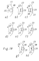
- blades 28 can also according to FIG. 10 (c) on the inside of the sword 27 inner blades 48 are provided.
- the inner blades 48 result in an additional stirring effect and at least partially compensate for the from the blades 28 originating and acting on the sword 27 one-sided Bending forces.
- the Formation of the sword 27 itself has an influence on the operating behavior. Is the sword 27 formed as a straight flat profile, results from the Width of the sword and the rotating movement an effective cross section, which is larger than the actual cross section (thickness x length) of the sword 27. The effective cross section can be reduced to the actual cross section, if the sword 27 is curved coaxially to the axis of rotation according to FIG. 10 (d). A further influence on the stirring characteristics results when the sword is inclined relative to the direction of rotation (tangent to the turning circle).
- the sword 27 points to the direction of travel (direction of rotation) related very small cross section. It can therefore be beneficial 10, if the edge of the sword lying in the direction of rotation according to FIG. 10 (g) 27 is designed as a cutting edge 49. This ensures that the resistance of the (especially powdery) mix does not become too large. The same applies the blades 28, which also have the smallest possible cross-section in the direction of movement should have. The goal is to move the mix upwards promote and thrust as little as possible. By not quite avoiding resistance always results in a promotion of Mix in the direction of rotation of the swords. Should this entrainment in the direction of rotation however, to increase the mixing strengthened and made usable 10, it is advantageous to have a take-along element on the sword 27 according to FIG. 10 (h) 50 e.g. in the form of a longitudinally extending sword 27 welded sheet metal strip. Other forms of Driving elements are of course also conceivable.
- the size and performance of the inventive can be in a wide range can be selected and are comparable to the size and performance of the known Screw cone mixer.
- the well-known screw cone mixer or dryer 1 with cantilevered mixing screw is used with container sizes, the a diameter of the base of about 1.45 m to about 2.60 m and have a height of about 1.70 m to about 3.55 m and depending on the container size have a useful volume of about 450 liters to 4000 liters.
- containers are used that a diameter of the base of about 2.10 m to about 4.80 m and one Have a height of about 2.80 m to about 7.00 m and one depending on the container size Have useful contents of about 1700 liters to 32000 liters.
- Comparable container sizes and useful contents are also in the stirring device according to the invention accessible and provided.
- a stirring tool can be used in which three swords acc. Fig. 5 (d) are arranged on a rotating circle with a diameter of 1800 mm, which rotate at a speed of 30 rpm around the container axis and are equipped with blades which have a length ( ⁇ spacing of the sword-container inner wall) of 100 mm and one Have an angle of attack of 15 °.
- the angle of attack of the blades (delivery angle) be between 1 ° and 45 ° and also over the length of the respective Sword vary.
- the speed for the swords can be between 5 and 300 Rpm.
- the number of swords is preferably between 1 and 20, the number of blades between 3 and 100.
- the blade length can be between 5 and 500 mm, the bucket width between 2 and 500 mm.
- the stirring device according to the invention can in principle be used in all methods use where a mix has to be stirred.
- the stirring device in the same way and in the same applications as more robust and inexpensive mixer can be used, as in the known Cone screw mixer is the case.
- the rigidly fixed and rotating around the container axis Shovels take on the function of the mixing screw. Against Above the mixing screw, they have the main advantage of a greatly simplified one and robust mechanics, in which the risk of contamination of the Mix is practically eliminated.
Landscapes
- Chemical & Material Sciences (AREA)
- Chemical Kinetics & Catalysis (AREA)
- Mixers Of The Rotary Stirring Type (AREA)
Abstract
Description
- Mischen und Homogenisieren von Trockenstoffen, Pasten und Slurries;
- Ein- und Aufdüsen von Flüssigkeiten in Trockenstoffe;
- Granulieren und Agglomerieren von Pulvern mit Hilfe eines Bindemittels;
- Reagieren unter Normal-, Ueberdruck oder Vakuum;
- Kristallisieren
- Inertisieren;
- Entlüften oder Belüften;
- Lagern und Austragen von schwerfliessenden Schüttgütern;
- Egalisieren von Farben oder Korngrössen;
- Kühlen; und
- Aufheizen.
- Fig. 1
- einen Schneckenkonusmischer aus dem Stand der Technik in der Seitenansicht;
- Fig. 2
- ein zu Fig. 1 vergleichbares erstes bevorzugtes Ausführungsbeispiel einer Rührvorrichtung nach der Erfindung mit einfach konischem Behälter und einem einzigen mit Schaufeln besetzten Schwert;
- Fig. 3
- ein zu Fig. 2 entsprechendes zweites Ausführungsbeispiel mit zwei zu einem Rahmen verbundenen Schwertern;
- Fig. 4
- ein Schwert mit Schaufeln gemäss Fig. 2 bzw. 3 in der Seitenansicht;
- Fig. 5a-d
- ausgehend von einer Rührvorrichtung mit einem Schwert gemäss Fig. 2 (Fig. 5(a)) die Anordnung der Schwerter in der Draufsicht von oben bei einem Schwert (Fig. 5(b)), bei zwei Schwertern (Fig. 5(c); und bei drei Schwertern (Fig. 5(d));
- Fig. 6
- ein weiteres bevorzugtes Ausführungsbeispiel einer Rührvorrichtung nach der Erfindung mit einer aus Zylinder-Oberteil und Konus-Unterteil zusammengesetzten Behälterform;
- Fig. 7
- ein anderes bevorzugtes Ausführungsbeispiel einer Rührvorrichtung nach der Erfindung mit einer zylindrischen Behälterform und ebenem Behälterboden;
- Fig. 8
- ein anderes bevorzugtes Ausführungsbeispiel einer Rührvorrichtung nach der Erfindung mit einer zylindrischen Behälterform und gewölbtem Behälterboden;
- Fig. 9
- eine speziell als Rührkessel ausgebildete Rührvorrichtung nach der Erfindung mit langer Welle, am unteren Ende der Welle befestigten Schwertern und zusätzlichen von oben in den Behälter hineinragenden Stromstörelementen; und
- Fig. 10a-h
- verschiedene Ausgestaltungen des Schwertes einer erfindungsgemässen Rührvorrichtung (Fig. 10(b)-(h)) im Vergleich zur Mischschnecke des bekannten Schneckenkonusmischers (Fig. 10(a)).
- 10
- Schneckenkonusmischer
- 11
- Behälter
- 12
- Mischraum
- 13
- Mischerboden
- 14
- Deckel
- 15
- Mischschnecke
- 16
- Umlenkgetriebe
- 17
- Schwenkarm
- 18
- Welle (Schwenkarm)
- 19
- Getriebeeinheit
- 20
- Antriebsmotor (Schwenkwelle)
- 21
- Antriebsmotor (Mischschnecke)
- 22
- Rührvorrichtung
- 23
- Behälter
- 24
- Innenraum (Behälter)
- 25
- Behälterboden
- 26
- Deckel
- 27;27a,b,c
- Schwert
- 28;28a,b
- Schaufel
- 29;29a,b,c
- Schwenkarm
- 30
- Welle
- 31
- Getriebeeinheit
- 32
- Antriebsmotor
- 33
- Behälterteil (zylindrisch)
- 34
- Behälterteil (konisch)
- 35,36
- Teilabschnitt (Schwert 27)
- 37,38
- Teilabschnitt (Schwert 27)
- 39
- Behälterboden (eben)
- 40,41
- Teilabschnitt (Schwert 27)
- 42
- Behälterboden (gewölbt)
- 43
- Welle
- 44
- Stromstörelement
- 45
- Achse (Mischer)
- 46
- Achse (Mischschnecke)
- 47
- Achse (Rührvorrichtung 22)
- 48
- Innenschaufel
- 49
- Schneide
- 50
- Mitnahmeelement
Claims (23)
- Vorrichtung (22) zum Rühren eines Rührgutes, umfassend einen Behälter (23) zur Aufnahme des Rührgutes und ein im Behälter (23) um eine senkrechte Achse (47) drehbar angeordnetes Rührwerkzeug (27; 27a,b,c; 28; 28a,b; 29; 29a,b,c; 48), welches das Rührgut beim Rührvorgang an der Innenwand des Behälters (23) nach oben transportiert, dadurch gekennzeichnet, dass das Rührwerkzeug an der Innenwand des Behälters (23) entlanggeführte Schaufeln (28; 28a,b; 48) umfasst, welche starr mit wenigstens einem um die Achse (47) drehbaren Schwenkarm (29; 29a,b,c) verbunden sind.
- Rührvorrichtung nach Anspruch 1, dadurch gekennzeichnet, dass das Rührwerkzeug wenigstens ein parallel zur Innenwand des Behälters (23) verlaufendes und mit dem wenigstens einen Schwenkarm (29; 29a,b,c) starr verbundenes Schwert (27; 27a,b,c) umfasst, an welchem die Schaufeln (28; 28a,b; 48) seitlich und in Längsrichtung des Schwertes (27; 27a,b,c) übereinander angeordnet sind.
- Rührvorrichtung nach Anspruch 2, dadurch gekennzeichnet, dass das wenigstens eine Schwert (27; 27a,b,c) von der Innenwand des Behälters (23) beabstandet ist, und dass die Schaufeln (28; 28a,b) zwischen dem Schwert (27; 27a,b,c) und der Innenwand des Behälters (23) angeordnet sind.
- Rührvorrichtung nach Anspruch 3, dadurch gekennzeichnet, dass auf der von der Innenwand des Behälters (23) abgewandten Seite des Schwertes (27) zusätzlich Innenschaufeln (48) angeordnet sind.
- Rührvorrichtung nach einem der Ansprüche 2 bis 4, dadurch gekennzeichnet, dass mehrere mit Schaufeln (28; 28a,b) besetzte Schwerter (27a,b,c) um die Achse (47) herum gleichmässig verteilt angeordnet und mit zugehörigen Schwenkarmen (29a,b,c) starr verbunden sind.
- Rührvorrichtung nach Anspruch 5, dadurch gekennzeichnet, dass die Schwerter (27a,b,c) an ihren von den Schwenkarmen (29a,b,c) abgewandten Enden untereinander verbunden sind und einen starren Käfig bilden.
- Rührvorrichtung nach einem der Ansprüche 1 bis 6, dadurch gekennzeichnet, dass die Schaufeln (28; 28a,b; 48) als schräg zur Achse (47) gestellte Bleche ausgebildet sind.
- Rührvorrichtung nach Anspruch 7, dadurch gekennzeichnet, dass die an der Innenwand des Behälters (23) entlanggeführten Schaufeln (28; 28a,b) an ihrem der Innenwand zugewandten Rand eine Randkontur aufweisen, die der Kontur der Innenwand angepasst ist.
- Rührvorrichtung nach Anspruch 2, dadurch gekennzeichnet, dass das wenigstens eine Schwert (27; 27a,b,c) als Flachprofil ausgebildet ist.
- Rührvorrichtung nach Anspruch 9, dadurch gekennzeichnet, dass das wenigstens eine Schwert (27; 27a,b,c) koaxial zur Achse (47) gekrümmt ist (Fig. 10(d)).
- Rührvorrichtung nach Anspruch 9, dadurch gekennzeichnet, dass das wenigstens eine Schwert (27; 27a,b,c) relativ zur Drehrichtung schräggestellt ist.
- Rührvorrichtung nach Anspruch 11, dadurch gekennzeichnet, dass die Schrägstellung so gewählt ist, dass das Rührgut durch das rotierende Schwert (27; 27a,b,c) nach aussen transportiert wird (Fig. 10(e)).
- Rührvorrichtung nach Anspruch 10, dadurch gekennzeichnet, dass die Schrägstellung so gewählt ist, dass das Rührgut durch das rotierende Schwert (27; 27a,b,c) nach innen transportiert wird (Fig. 10(f)).
- Rührvorrichtung nach Anspruch 9, dadurch gekennzeichnet, dass die in Drehrichtung liegende Kante des wenigstens einen Schwertes (27; 27a,b,c) als Schneide (49) ausgebildet ist (Fig. 10(g)).
- Rührvorrichtung nach Anspruch 9, dadurch gekennzeichnet, dass an der Innenseite des wenigstens einen Schwertes (27; 27a,b,c) ein zusätzliches Mitnahmeelement (50) zur Mitnahme von Rührgut während der Drehbewegung angeordnet ist.
- Rührvorrichtung nach einem der Ansprüche 1 bis 15, dadurch gekennzeichnet, dass der Behälter (23) einfach konisch ausgebildet ist und sich nach unten hin verjüngt.
- Rührvorrichtung nach einem der Ansprüche 1 bis 15, dadurch gekennzeichnet, dass der Behälter (23) in einen obenliegenden zylindrischen Behälterteil (33) und einen daran nach unten anschliessenden konischen Behälterteil (34) unterteilt ist, und dass das Rührwerkzeug bzw. das wenigstens eine Schwert (27; 27a,b,c) in zwei Teilabschnitte (35, 36) unterteilt ist, welche den Innenwänden des jeweiligen Behälterteils (33 bzw. 34) angepasst sind.
- Rührvorrichtung nach einem der Ansprüche 1 bis 15, dadurch gekennzeichnet, dass der Behälter (23) zylindrisch ausgebildet ist, und dass das Rührwerkzeug bzw. das wenigstens eine Schwert (27; 27a,b,c) in zwei Teilabschnitte (37, 38 bzw. 40, 41) unterteilt ist, von denen der eine an die Innnenwand des Behälters (23) und der andere an den Behälterboden (39 bzw. 42) angepasst ist.
- Rührvorrichtung nach einem der Ansprüche 1 bis 18, dadurch gekennzeichnet, dass die Wände des Behälters (23) und/der das Rührwerkzeug heizbar ausgebildet sind.
- Rührvorrichtung nach Anspruch 19, dadurch gekennzeichnet, dass im Inneren des vom Rührwerkzeug bzw. vom wenigstens einen Schwert (27; 27a,b,c) beschriebenen Kreises wenigstens ein Stromstörelement (44) angeordnet ist.
- Anwendung der Rührvorrichtung (22) nach einem der Ansprüche 1 bis 18 als Mischer.
- Anwendung der Rührvorrichtung (22) nach einem der Ansprüche 1 bis 19 als Kontakttrockner.
- Anwendung der Rührvorrichtung (22) nach einem der Ansprüche 1 bis 20 als Rührkessel.
Applications Claiming Priority (2)
| Application Number | Priority Date | Filing Date | Title |
|---|---|---|---|
| CH6398 | 1998-01-14 | ||
| CH6398 | 1998-01-14 |
Publications (2)
| Publication Number | Publication Date |
|---|---|
| EP0930093A2 true EP0930093A2 (de) | 1999-07-21 |
| EP0930093A3 EP0930093A3 (de) | 2001-03-21 |
Family
ID=4178469
Family Applications (1)
| Application Number | Title | Priority Date | Filing Date |
|---|---|---|---|
| EP99810014A Withdrawn EP0930093A3 (de) | 1998-01-14 | 1999-01-12 | Vorrichtung zum Rühren eines Rührgutes sowie Anwendung der Rührvorrichtung |
Country Status (2)
| Country | Link |
|---|---|
| EP (1) | EP0930093A3 (de) |
| JP (1) | JPH11276873A (de) |
Cited By (6)
| Publication number | Priority date | Publication date | Assignee | Title |
|---|---|---|---|---|
| CN110339758A (zh) * | 2019-08-14 | 2019-10-18 | 义乌工商职业技术学院 | 清洗液混合设备及清洗机 |
| CN112588149A (zh) * | 2020-11-23 | 2021-04-02 | 上海健康医学院 | 一种生产中草药牙膏的真空搅拌制膏机 |
| CN114272808A (zh) * | 2021-03-16 | 2022-04-05 | 卫纳塞德(北京)医疗科技有限公司 | 一种用于医疗药物配置的搅拌装置 |
| CN117398882A (zh) * | 2023-12-14 | 2024-01-16 | 山东鲁源化工科技有限公司 | 一种化工原料混合设备及其混合方法 |
| CN118496923A (zh) * | 2024-07-12 | 2024-08-16 | 山东惠农玫瑰股份有限公司 | 一种玫瑰精油提取装置及提取方法 |
| CN119796721A (zh) * | 2025-01-03 | 2025-04-11 | 中国原子能科学研究院 | 一种固体物料输送装置 |
Families Citing this family (1)
| Publication number | Priority date | Publication date | Assignee | Title |
|---|---|---|---|---|
| NL2013779B1 (en) * | 2014-11-12 | 2016-10-07 | Xeikon Ip Bv | Stirring apparatus and method for stirring a liquid. |
Family Cites Families (5)
| Publication number | Priority date | Publication date | Assignee | Title |
|---|---|---|---|---|
| US3544081A (en) * | 1968-03-15 | 1970-12-01 | Hans A Eckhardt | Apparatus for mixing flowable materials |
| US4274751A (en) * | 1980-03-26 | 1981-06-23 | E. I. Du Pont De Nemours And Company | Scraped wall agitator |
| DE3332069A1 (de) * | 1983-09-06 | 1985-03-21 | Hoechst Ag | Ruehrer fuer wandnahes ruehren |
| JPS6146230A (ja) * | 1984-08-11 | 1986-03-06 | Matsushita Electric Works Ltd | 反応釜 |
| JP3648279B2 (ja) * | 1995-01-09 | 2005-05-18 | 佐竹化学機械工業株式会社 | 中・高粘度用撹拌翼 |
-
1999
- 1999-01-12 EP EP99810014A patent/EP0930093A3/de not_active Withdrawn
- 1999-01-14 JP JP11008019A patent/JPH11276873A/ja active Pending
Cited By (7)
| Publication number | Priority date | Publication date | Assignee | Title |
|---|---|---|---|---|
| CN110339758A (zh) * | 2019-08-14 | 2019-10-18 | 义乌工商职业技术学院 | 清洗液混合设备及清洗机 |
| CN112588149A (zh) * | 2020-11-23 | 2021-04-02 | 上海健康医学院 | 一种生产中草药牙膏的真空搅拌制膏机 |
| CN114272808A (zh) * | 2021-03-16 | 2022-04-05 | 卫纳塞德(北京)医疗科技有限公司 | 一种用于医疗药物配置的搅拌装置 |
| CN117398882A (zh) * | 2023-12-14 | 2024-01-16 | 山东鲁源化工科技有限公司 | 一种化工原料混合设备及其混合方法 |
| CN117398882B (zh) * | 2023-12-14 | 2024-03-08 | 山东鲁源化工科技有限公司 | 一种化工原料混合设备及其混合方法 |
| CN118496923A (zh) * | 2024-07-12 | 2024-08-16 | 山东惠农玫瑰股份有限公司 | 一种玫瑰精油提取装置及提取方法 |
| CN119796721A (zh) * | 2025-01-03 | 2025-04-11 | 中国原子能科学研究院 | 一种固体物料输送装置 |
Also Published As
| Publication number | Publication date |
|---|---|
| JPH11276873A (ja) | 1999-10-12 |
| EP0930093A3 (de) | 2001-03-21 |
Similar Documents
| Publication | Publication Date | Title |
|---|---|---|
| EP0802879B1 (de) | Vorrichtung zum dosieren von schüttgut | |
| DE2709309C3 (de) | Vorrichtung zum Austragen von fließfähigem Gut | |
| DE69201627T2 (de) | Einrichtung zum Fördern und volumetrischen Dosieren von Schüttgut. | |
| DE7834517U1 (de) | Schneckenfoerderer mit einem zwischenlager | |
| DE60104086T2 (de) | Schneckenfördereinrichtung für Flüssigkeiten und/oder Materialbrocken | |
| EP1175828A2 (de) | Vertikalmischer für Futter | |
| DE2160410A1 (de) | Mischvorrichtung | |
| EP0039427B1 (de) | Fördervorrichtung zum Befüllen mit Erntegut des Sammelbehälters eines Mähdreschers | |
| DE2731212A1 (de) | Foerderschneckenvorrichtung fuer partikelmaterial | |
| DE1642984A1 (de) | Verbesserte Reaktoren fuer viskose Reaktionsteilnehmer | |
| DE69501804T2 (de) | Trocknungsvorrichtung und -verfahren | |
| EP3095510B1 (de) | Rührwerk und behälter mit rührwerk | |
| DE2147280C3 (de) | Vorrichtung zum Mischen von schüttbarem Erntegut | |
| DE69105169T2 (de) | Feinmahlanlage. | |
| DE2830491C2 (de) | ||
| DE1298401B (de) | Zwangsmischer mit lotrecht angeordnetem Mischbehaelter | |
| EP0930093A2 (de) | Vorrichtung zum Rühren eines Rührgutes sowie Anwendung der Rührvorrichtung | |
| EP0450012A1 (de) | Einrichtung und verfahren zum mischen und/oder granulieren eines gutes. | |
| DE1917705C3 (de) | Einrichtung zum thermischen Behandeln von flüssigem Material in dünner Schicht | |
| DE1657111A1 (de) | Vorrichtung zur Handhabung von Schuettguetern,insbesondere Getreide | |
| DE3503947C2 (de) | Trommel zum Agglomerieren | |
| DE10106798A1 (de) | Dosiervorrichtung | |
| DE1291185B (de) | Maschine zum Mischen und Foerdern von Schuettgut | |
| DE2043608C2 (de) | Tellermischer | |
| DE1945615A1 (de) | Verfahren und Anlage zum Verfluessigen und Verruehren raffinierter Schokolade |
Legal Events
| Date | Code | Title | Description |
|---|---|---|---|
| PUAI | Public reference made under article 153(3) epc to a published international application that has entered the european phase |
Free format text: ORIGINAL CODE: 0009012 |
|
| AK | Designated contracting states |
Kind code of ref document: A2 Designated state(s): AT BE CH DE ES FI FR GB IE IT LI NL SE |
|
| AX | Request for extension of the european patent |
Free format text: AL;LT;LV;MK;RO;SI |
|
| PUAL | Search report despatched |
Free format text: ORIGINAL CODE: 0009013 |
|
| AK | Designated contracting states |
Kind code of ref document: A3 Designated state(s): AT BE CH CY DE DK ES FI FR GB GR IE IT LI LU MC NL PT SE |
|
| AX | Request for extension of the european patent |
Free format text: AL;LT;LV;MK;RO;SI |
|
| RIC1 | Information provided on ipc code assigned before grant |
Free format text: 7B 01F 7/00 A, 7B 01F 7/16 B, 7B 01F 7/18 B, 7B 01F 15/00 B |
|
| AKX | Designation fees paid |
Free format text: AT BE CH DE ES FI FR GB IE IT LI NL SE |
|
| STAA | Information on the status of an ep patent application or granted ep patent |
Free format text: STATUS: THE APPLICATION IS DEEMED TO BE WITHDRAWN |
|
| 18D | Application deemed to be withdrawn |
Effective date: 20010922 |