EP0928884A2 - Dispositif de distribution d'un mélange - Google Patents
Dispositif de distribution d'un mélange Download PDFInfo
- Publication number
- EP0928884A2 EP0928884A2 EP98118527A EP98118527A EP0928884A2 EP 0928884 A2 EP0928884 A2 EP 0928884A2 EP 98118527 A EP98118527 A EP 98118527A EP 98118527 A EP98118527 A EP 98118527A EP 0928884 A2 EP0928884 A2 EP 0928884A2
- Authority
- EP
- European Patent Office
- Prior art keywords
- reducing agent
- consumption container
- agent consumption
- control valve
- pressure control
- Prior art date
- Legal status (The legal status is an assumption and is not a legal conclusion. Google has not performed a legal analysis and makes no representation as to the accuracy of the status listed.)
- Granted
Links
Images

Classifications
-
- F—MECHANICAL ENGINEERING; LIGHTING; HEATING; WEAPONS; BLASTING
- F01—MACHINES OR ENGINES IN GENERAL; ENGINE PLANTS IN GENERAL; STEAM ENGINES
- F01N—GAS-FLOW SILENCERS OR EXHAUST APPARATUS FOR MACHINES OR ENGINES IN GENERAL; GAS-FLOW SILENCERS OR EXHAUST APPARATUS FOR INTERNAL COMBUSTION ENGINES
- F01N9/00—Electrical control of exhaust gas treating apparatus
-
- F—MECHANICAL ENGINEERING; LIGHTING; HEATING; WEAPONS; BLASTING
- F01—MACHINES OR ENGINES IN GENERAL; ENGINE PLANTS IN GENERAL; STEAM ENGINES
- F01N—GAS-FLOW SILENCERS OR EXHAUST APPARATUS FOR MACHINES OR ENGINES IN GENERAL; GAS-FLOW SILENCERS OR EXHAUST APPARATUS FOR INTERNAL COMBUSTION ENGINES
- F01N3/00—Exhaust or silencing apparatus having means for purifying, rendering innocuous, or otherwise treating exhaust
- F01N3/08—Exhaust or silencing apparatus having means for purifying, rendering innocuous, or otherwise treating exhaust for rendering innocuous
- F01N3/10—Exhaust or silencing apparatus having means for purifying, rendering innocuous, or otherwise treating exhaust for rendering innocuous by thermal or catalytic conversion of noxious components of exhaust
- F01N3/18—Exhaust or silencing apparatus having means for purifying, rendering innocuous, or otherwise treating exhaust for rendering innocuous by thermal or catalytic conversion of noxious components of exhaust characterised by methods of operation; Control
- F01N3/20—Exhaust or silencing apparatus having means for purifying, rendering innocuous, or otherwise treating exhaust for rendering innocuous by thermal or catalytic conversion of noxious components of exhaust characterised by methods of operation; Control specially adapted for catalytic conversion ; Methods of operation or control of catalytic converters
- F01N3/2066—Selective catalytic reduction [SCR]
-
- F—MECHANICAL ENGINEERING; LIGHTING; HEATING; WEAPONS; BLASTING
- F01—MACHINES OR ENGINES IN GENERAL; ENGINE PLANTS IN GENERAL; STEAM ENGINES
- F01N—GAS-FLOW SILENCERS OR EXHAUST APPARATUS FOR MACHINES OR ENGINES IN GENERAL; GAS-FLOW SILENCERS OR EXHAUST APPARATUS FOR INTERNAL COMBUSTION ENGINES
- F01N3/00—Exhaust or silencing apparatus having means for purifying, rendering innocuous, or otherwise treating exhaust
- F01N3/08—Exhaust or silencing apparatus having means for purifying, rendering innocuous, or otherwise treating exhaust for rendering innocuous
- F01N3/10—Exhaust or silencing apparatus having means for purifying, rendering innocuous, or otherwise treating exhaust for rendering innocuous by thermal or catalytic conversion of noxious components of exhaust
- F01N3/24—Exhaust or silencing apparatus having means for purifying, rendering innocuous, or otherwise treating exhaust for rendering innocuous by thermal or catalytic conversion of noxious components of exhaust characterised by constructional aspects of converting apparatus
- F01N3/36—Arrangements for supply of additional fuel
-
- F—MECHANICAL ENGINEERING; LIGHTING; HEATING; WEAPONS; BLASTING
- F01—MACHINES OR ENGINES IN GENERAL; ENGINE PLANTS IN GENERAL; STEAM ENGINES
- F01N—GAS-FLOW SILENCERS OR EXHAUST APPARATUS FOR MACHINES OR ENGINES IN GENERAL; GAS-FLOW SILENCERS OR EXHAUST APPARATUS FOR INTERNAL COMBUSTION ENGINES
- F01N2610/00—Adding substances to exhaust gases
- F01N2610/02—Adding substances to exhaust gases the substance being ammonia or urea
-
- F—MECHANICAL ENGINEERING; LIGHTING; HEATING; WEAPONS; BLASTING
- F01—MACHINES OR ENGINES IN GENERAL; ENGINE PLANTS IN GENERAL; STEAM ENGINES
- F01N—GAS-FLOW SILENCERS OR EXHAUST APPARATUS FOR MACHINES OR ENGINES IN GENERAL; GAS-FLOW SILENCERS OR EXHAUST APPARATUS FOR INTERNAL COMBUSTION ENGINES
- F01N2610/00—Adding substances to exhaust gases
- F01N2610/08—Adding substances to exhaust gases with prior mixing of the substances with a gas, e.g. air
-
- F—MECHANICAL ENGINEERING; LIGHTING; HEATING; WEAPONS; BLASTING
- F01—MACHINES OR ENGINES IN GENERAL; ENGINE PLANTS IN GENERAL; STEAM ENGINES
- F01N—GAS-FLOW SILENCERS OR EXHAUST APPARATUS FOR MACHINES OR ENGINES IN GENERAL; GAS-FLOW SILENCERS OR EXHAUST APPARATUS FOR INTERNAL COMBUSTION ENGINES
- F01N2610/00—Adding substances to exhaust gases
- F01N2610/10—Adding substances to exhaust gases the substance being heated, e.g. by heating tank or supply line of the added substance
-
- F—MECHANICAL ENGINEERING; LIGHTING; HEATING; WEAPONS; BLASTING
- F01—MACHINES OR ENGINES IN GENERAL; ENGINE PLANTS IN GENERAL; STEAM ENGINES
- F01N—GAS-FLOW SILENCERS OR EXHAUST APPARATUS FOR MACHINES OR ENGINES IN GENERAL; GAS-FLOW SILENCERS OR EXHAUST APPARATUS FOR INTERNAL COMBUSTION ENGINES
- F01N2610/00—Adding substances to exhaust gases
- F01N2610/14—Arrangements for the supply of substances, e.g. conduits
-
- Y—GENERAL TAGGING OF NEW TECHNOLOGICAL DEVELOPMENTS; GENERAL TAGGING OF CROSS-SECTIONAL TECHNOLOGIES SPANNING OVER SEVERAL SECTIONS OF THE IPC; TECHNICAL SUBJECTS COVERED BY FORMER USPC CROSS-REFERENCE ART COLLECTIONS [XRACs] AND DIGESTS
- Y02—TECHNOLOGIES OR APPLICATIONS FOR MITIGATION OR ADAPTATION AGAINST CLIMATE CHANGE
- Y02T—CLIMATE CHANGE MITIGATION TECHNOLOGIES RELATED TO TRANSPORTATION
- Y02T10/00—Road transport of goods or passengers
- Y02T10/10—Internal combustion engine [ICE] based vehicles
- Y02T10/12—Improving ICE efficiencies
-
- Y—GENERAL TAGGING OF NEW TECHNOLOGICAL DEVELOPMENTS; GENERAL TAGGING OF CROSS-SECTIONAL TECHNOLOGIES SPANNING OVER SEVERAL SECTIONS OF THE IPC; TECHNICAL SUBJECTS COVERED BY FORMER USPC CROSS-REFERENCE ART COLLECTIONS [XRACs] AND DIGESTS
- Y02—TECHNOLOGIES OR APPLICATIONS FOR MITIGATION OR ADAPTATION AGAINST CLIMATE CHANGE
- Y02T—CLIMATE CHANGE MITIGATION TECHNOLOGIES RELATED TO TRANSPORTATION
- Y02T10/00—Road transport of goods or passengers
- Y02T10/10—Internal combustion engine [ICE] based vehicles
- Y02T10/40—Engine management systems
Definitions
- the invention is based on a mixture dispensing device according to the genus of the main claim. It also exists the demand for a harmful reduction continues Exhaust gas components from internal combustion engines.
- a urea-water solution is provided a catalyst in the exhaust system of the internal combustion engine brought in.
- the urea introduced is in the catalyst converted into ammonia by chemical reactions, which the reduction of nitrogen oxides.
- features of the main claim have the advantage that in a simple way on the use of a Urea feed pump can be dispensed with and also at Always need large amounts of urea water solution sufficient stock is available, although only for a smaller one, the urea-water solution receptacle Pressure vessel regulation must be observed. This The consumption container is quickly removed from the break Refillable with the urea-water solution and can be supplied with the required gas pressure.
- a control valve is provided in a first Switch position a connection from Reducing agent consumption container for the first Manufactures pressure control valve and in a second Switch position the connection to the first pressure control valve interrupts and connects a gas space of the Reducing agent consumption container opens to the atmosphere.
- Reducing agent consumption container opening Check valve to arrange or instead Refill valve that in a first switch position Connection between the reducing agent reservoir and interrupts the reducing agent consumption container and in a second switch position for refilling the Reducing agent consumption container opens this connection. This ensures that from Reductant reservoir a quick filling of the Reducing agent consumption container can be made, but a Return flow from the reducing agent consumption container to Reductant reservoir is prevented.
- the level of the urea-water solution measuring level sensor arranged at Another maximum is reached Filling interrupts and at the latest when one is reached certain minimum filling level a refill of the Initiates reducing agent consumption container.
- Reducing agent consumption container a heating element arranged, which freezes at too low temperatures Prevents urea-water solution or thawing causes.
- Embodiments of the invention are in the drawing shown in simplified form and in the following Description explained in more detail.
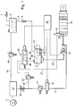
- 1 shows a first Embodiment of a schematically illustrated Mixture dispenser of urea for an exhaust system an internal combustion engine
- Figure 2 shows a second Embodiment of a schematically illustrated Mixture dispenser of urea for an exhaust system an internal combustion engine.
- a Reducing agent reservoir 1 is provided, which at a Commercial vehicle application a capacity of approx. 50 l for a urea-water solution.
- the Reducing agent reservoir 1 leads one Supply line 2 to one Reducing agent consumption container 3.
- the volume of the Reducing agent consumption container 3 only corresponds a fraction of the volume of the Reducing agent storage container 1.
- the mixture dispensing device also has a pump 11 on, the gas under a pressure of, for example, 7 bar in promotes a gas storage 12.
- a gas z. B. air Exhaust gas from the exhaust system of the internal combustion engine or an other gas.
- the gas storage 12 is also one Compressed gas line 13 connected in series adjustable throttle valve 16, a metering pressure control valve 17 and an electromagnetically actuated gas control valve 18 are arranged.
- the metering pressure control valve 17 controls the downstream pressure in the compressed gas line 13 for example to about 1 bar. That as a 2/2-way valve trained gas control valve 18 has a blocking position, in which it is shown in Figure 1, and a Open position.
- Urea pressure line 20 Urea pressure line 20 to a metering and Mixing device 21 which can be actuated electromagnetically and to which the compressed gas line 13 also leads.
- a metering and Mixing device 21 In the Dosing and mixing device 21 is a mixture of Urea-water solution supplied via the urea pressure line 20 with via the compressed gas line 13 supplied compressed gas.
- the dosage of Urea-water solution for example by means of a non injectors, for example one known from DE 34 11 537 A1 injection valve for the gasoline injection.
- a non injectors for example one known from DE 34 11 537 A1 injection valve for the gasoline injection.
- the dosed urea-water solution in a mixing room Compressed gas supplied to form a homogeneous mixture.
- the control of the gas control valve 18 and the metering and Mixing device 21 is carried out by an electronic Control unit 22. That by means of the compressed gas evenly and finely prepared mixture with the urea-water solution is in an exhaust system 23 by means of a provided thereon Atomizer device 25 upstream of a catalytic converter 26 known type blown.
- the atomizer device 25 is in the simplest form through a nozzle with a Blow-out opening is formed, but several can also be used Blow-out openings may be provided.
- the in the catalyst 26 The urea introduced by chemical reactions in Converts ammonia, which reduces nitrogen oxides in the Exhaust causes.
- a branch gas line 27 from that to an above the urea-water solution in the Reductant consumption container 3 formed gas space 30 leads and through which a connection from Reducing agent consumption container 3 to the compressed gas source can be produced by the pump 11 and the gas storage 12 is formed.
- the branch gas line 27 is one in series first pressure control valve 31 and downstream thereof Control valve 32 arranged.
- the first pressure control valve 31 regulates a gas pressure downstream in the branch gas line 27 of approx. 3 bar.
- the control valve 32 is in the present Embodiment designed as a 3/3-way valve and Electromagnetically confirmed by the electronic Control unit 22 can be controlled.
- first switching position 35th one in which this is a connection between the first Pressure control valve 31 and the Manufactures reducing agent consumption container 3 while it in a second switching position 36 the connection between the reducing agent consumption container 3 and the first Pressure control valve 31 interrupts and a connection from Gas space 30 of the reducing agent consumption container 3 to a relief line 37 that opens to the exhaust system 23 and thus leads to the atmosphere.
- this takes a third switching position 40 in which the connection from Reducing agent consumption container 3 for the first Pressure control valve 31 and thus to the gas pressure source 11, 12 and the connection to the relief line 37 is interrupted.
- a Fill level of the urea-water solution in the Reducing agent consumption container 3 measuring Level sensor 41 of a known type arranged, the for example works on a photo-optical basis and with the electronic control unit 22 is connected to at least then measurement signals to the electronic control unit 22nd forward when the minimum or maximum fill level the urea-water solution in the Reducing agent consumption container 3 is reached, so one Refill the urea-water solution in the Initiate or to reduce reducing agent consumption container interrupt.
- Level sensor 41 of a known type arranged, the for example works on a photo-optical basis and with the electronic control unit 22 is connected to at least then measurement signals to the electronic control unit 22nd forward when the minimum or maximum fill level the urea-water solution in the Reducing agent consumption container 3 is reached, so one Refill the urea-water solution in the Initiate or to reduce reducing agent consumption container interrupt.
- a connecting line 45 leads from gas storage 12 to Reductant reservoir 1.
- a second pressure control valve 46 is arranged, one Gas pressure of approx. 1.2 bar in the reducing agent reservoir 1 regulates.
- the mixture dispensing device according to the invention is required no feed pump for generating pressure for those in the Exhaust system 23 of the internal combustion engine to be blown Urea water solution. That in the first switch position 35 of the control valve 32 in the Reducing agent consumption container 3 introduced compressed gas causes a pressure build-up at the same height in the Urea water solution in Reducing agent consumption container 3, which is thus on the Urea pressure line 20 under this pressure of the metering and Mixing device 21 is fed. At the latest when in the reducing agent consumption container 3 by the Level sensor 41 reaching the minimum Level of the urea-water solution signals is, the electronic control unit 22 Control valve 32 in its second switching position 36 switched and thus the pressure in Reducing agent consumption container 3 almost to about Relieved atmospheric pressure.
- This refill the Reducing agent consumption container 3 can for example also be regulated so that the dosing and Mixing device 21 or when turning off the Internal combustion engine or at a start of the Internal combustion engine with the electronic control unit 22 a fill level of the urea-water solution below the maximum fill level, the control valve 32 in the described Controls to refill the Reducing agent consumption container 3 up to the maximum Level of the urea-water solution.
- a mixture dispenser according to the invention differs from the first embodiment Figure 1 only in that the control valve 32 as a 2/2-way valve with the first switch position 35 and the second Switch position 36 is formed, so no longer the blocking third switching position of the control valve 32 after Figure 1 has and instead of the check valve 5 in the Supply line 2, a refill valve 48 is provided.
- the refill valve 48 is Electromagnetically controlled by the electronic Control unit 22 and has a through position 49 in which it the supply line 2 from the reducing agent reservoir 1 to the reducing agent consumption container 3 opens while it assumes a blocking position 50 in the non-excited state.
- control valve 32 of the The embodiment of Figure 2 corresponds to Operation of the control valve 32 of the embodiment according to Figure 1.
- the refill valve 48 is then always the electronic control valve to the through position 49 switched when urea water solution from the Reducing agent reservoir 1 in the Reducing agent consumption container 3 are refilled should.
Landscapes
- Engineering & Computer Science (AREA)
- Chemical & Material Sciences (AREA)
- Chemical Kinetics & Catalysis (AREA)
- Combustion & Propulsion (AREA)
- Mechanical Engineering (AREA)
- General Engineering & Computer Science (AREA)
- Health & Medical Sciences (AREA)
- Toxicology (AREA)
- Exhaust Gas After Treatment (AREA)
Applications Claiming Priority (2)
| Application Number | Priority Date | Filing Date | Title |
|---|---|---|---|
| DE19800421A DE19800421A1 (de) | 1998-01-08 | 1998-01-08 | Gemischabgabevorrichtung |
| DE19800421 | 1998-01-08 |
Publications (3)
| Publication Number | Publication Date |
|---|---|
| EP0928884A2 true EP0928884A2 (fr) | 1999-07-14 |
| EP0928884A3 EP0928884A3 (fr) | 2003-01-02 |
| EP0928884B1 EP0928884B1 (fr) | 2006-09-27 |
Family
ID=7854149
Family Applications (1)
| Application Number | Title | Priority Date | Filing Date |
|---|---|---|---|
| EP98118527A Expired - Lifetime EP0928884B1 (fr) | 1998-01-08 | 1998-09-30 | Dispositif de distribution d'un mélange |
Country Status (2)
| Country | Link |
|---|---|
| EP (1) | EP0928884B1 (fr) |
| DE (2) | DE19800421A1 (fr) |
Cited By (29)
| Publication number | Priority date | Publication date | Assignee | Title |
|---|---|---|---|---|
| WO2001038703A1 (fr) * | 1999-11-24 | 2001-05-31 | Siemens Aktiengesellschaft | Dispositif et procede de denitrogenisation des gaz d'echappement d'un moteur a combustion interne |
| WO2002057603A1 (fr) * | 2001-01-19 | 2002-07-25 | Robert Bosch Gmbh | Dispositif de dosage d'une composition d'uree depourvue d'enzymes, avec une unite de detection permettant la verification de grandeurs physiques d'etat de la composition d'uree |
| WO2005045209A1 (fr) * | 2003-11-04 | 2005-05-19 | Robert Bosch Gmbh | Dispositif d'introduction d'un agent reducteur dans les gaz d'echappement d'un moteur a combustion interne |
| EP1612381A1 (fr) | 2004-06-30 | 2006-01-04 | Iveco S.p.A. | Système et procédé pour injecter un liquide dans un courant de gaz, dispositif de traitement de gaz d'échappement et véhicule contenant ce dispositif |
| WO2007017080A1 (fr) * | 2005-08-06 | 2007-02-15 | Eichenauer Heizelemente Gmbh & Co. Kg | Systeme de chauffage |
| DE102006061732A1 (de) | 2006-12-28 | 2008-07-03 | Robert Bosch Gmbh | Vorrichtung zum Dosieren eines flüssigen Reduktionsmittels |
| DE102006061734A1 (de) | 2006-12-28 | 2008-07-03 | Robert Bosch Gmbh | Vorrichtung zum Dosieren eines Reduktionsmittels |
| WO2008092612A1 (fr) | 2007-02-01 | 2008-08-07 | Bayerische Motoren Werke Aktiengesellschaft | Dispositif d'introduction d'un additif liquide pour un moteur à combustion interne |
| WO2008092613A1 (fr) | 2007-02-01 | 2008-08-07 | Bayerische Motoren Werke Aktiengesellschaft | Dispositif d'introduction d'un additif liquide pour un moteur à combustion interne |
| WO2009045325A1 (fr) * | 2007-09-28 | 2009-04-09 | Caterpillar Inc. | Système de post-traitement d'échappement ayant un réservoir auxiliaire |
| WO2009090101A1 (fr) * | 2008-01-17 | 2009-07-23 | Inergy Automotive Systems Research (Societe Anonyme) | Procédé pour transférer un liquide à l'aide d'une pompe |
| US7594393B2 (en) | 2004-09-07 | 2009-09-29 | Robert Bosch Gmbh | Apparatus for introducing a reducing agent into the exhaust of an internal combustion engine |
| DE102008000932A1 (de) | 2008-04-02 | 2009-10-08 | Robert Bosch Gmbh | Vorrichtung zum Dosieren eines flüssigen Reduktionsmittels |
| WO2009121649A1 (fr) * | 2008-04-02 | 2009-10-08 | Robert Bosch Gmbh | Système scr doté de plusieurs réservoirs |
| WO2009156204A1 (fr) * | 2008-06-24 | 2009-12-30 | Robert Bosch Gmbh | Dispositif de post-traitement des gaz d'échappement d'un moteur à combustion interne |
| WO2010009790A1 (fr) | 2008-07-23 | 2010-01-28 | Bayerische Motoren Werke Aktiengesellschaft | Réservoir d'agent de réduction doté d'une soupape d'arrêt pour alimenter un système d'échappement en agent de réduction |
| DE102008041903A1 (de) | 2008-09-09 | 2010-03-11 | Robert Bosch Gmbh | Verfahren und Vorrichtung zur Nachbehandlung des Abgases einer Brennkraftmaschine |
| DE102008041805A1 (de) | 2008-09-04 | 2010-03-11 | Robert Bosch Gmbh | Tankanordnung |
| CN101975103A (zh) * | 2010-10-20 | 2011-02-16 | 中国第一汽车集团公司 | 气动式双尿素箱电控尿素泵水加热scr尿素系统 |
| CN101975102A (zh) * | 2010-10-20 | 2011-02-16 | 中国第一汽车集团公司 | 气动式单尿素箱全放气清空管路scr尿素系统 |
| CN101979131A (zh) * | 2010-10-20 | 2011-02-23 | 中国第一汽车集团公司 | 气动式双尿素箱尿素单向阀控制水加热scr尿素系统 |
| WO2011135043A1 (fr) * | 2010-04-30 | 2011-11-03 | Inergy Automotive Systems Research S.A. | Procédé pour transférer un liquide à l'aide d'une pompe |
| WO2012031810A1 (fr) * | 2010-09-09 | 2012-03-15 | Robert Bosch Gmbh | Système de retraitement des gaz d'échappement et procédé d'introduction d'une quantité dosée d'une substance dans la ligne d'échappement d'un moteur à combustion interne |
| CN102388208A (zh) * | 2009-04-16 | 2012-03-21 | 因勒纪汽车系统研究公司 | 用于存储添加剂并将它注入发动机排气的系统和方法 |
| CN102451617A (zh) * | 2010-10-20 | 2012-05-16 | 中国第一汽车集团公司 | 气动式双尿素箱电控尿素加注泵内置滤清器scr尿素系统 |
| DE102011081580A1 (de) | 2011-03-04 | 2012-09-06 | Robert Bosch Gmbh | Abgasnachbehandlungssystem einer Brennkraftmaschine und Verfahren zur Eindosierung einer Flüssigkeit in den Abgaskanal der Brennkraftmaschine |
| EP3032059A1 (fr) * | 2014-12-09 | 2016-06-15 | Delphi International Operations Luxembourg S.à r.l. | Système de dosage scr |
| EP3156621A1 (fr) * | 2015-10-13 | 2017-04-19 | Clark Equipment Company | Alimentation en fluide à distance pour un moteur |
| DE102007005005B4 (de) | 2007-02-01 | 2022-06-30 | Bayerische Motoren Werke Aktiengesellschaft | Einrichtung für eine Brennkraftmaschine zum Zuführen eines flüssigen Additivs |
Families Citing this family (5)
| Publication number | Priority date | Publication date | Assignee | Title |
|---|---|---|---|---|
| DE19952428A1 (de) * | 1999-10-30 | 2001-05-03 | Man Nutzfahrzeuge Ag | Verfahren und Vorrichtung zur kombinierten katalytischen NOx-Reduktion und Schalldämpfung von Abgas im Abgasstrang einer Brennkraftmaschine |
| DE20119514U1 (de) | 2001-12-03 | 2002-02-28 | PUREM Abgassysteme GmbH & Co. KG, 58706 Menden | Reduktionsmitteldosiereinrichtung |
| WO2006131201A2 (fr) * | 2005-06-04 | 2006-12-14 | Eichenauer Heizelemente Gmbh & Co.Kg | Systeme d'apport d'uree pour catalyseur de purification de gaz d'echappement, et element chauffant approprie |
| DE102007035938A1 (de) | 2007-07-31 | 2009-02-05 | Eberspächer Unna GmbH & Co. KG | Reduktionsmitteldosiersystem und -Verfahren |
| DE102008034213A1 (de) * | 2008-07-23 | 2010-01-28 | Bayerische Motoren Werke Aktiengesellschaft | Reduktionsmitteltank zum Bereitstellen von Reduktionsmittel an einer Abgasanalge mit mindestens zwei Behältern |
Citations (2)
| Publication number | Priority date | Publication date | Assignee | Title |
|---|---|---|---|---|
| DE3411537A1 (de) | 1984-03-29 | 1985-10-10 | Robert Bosch Gmbh, 7000 Stuttgart | Elektromagnetisch betaetigbares kraftstoffeinspritzventil |
| EP0586913A2 (fr) | 1992-09-08 | 1994-03-16 | MAN Nutzfahrzeuge Aktiengesellschaft | Dispositif de pulvérisation |
Family Cites Families (3)
| Publication number | Priority date | Publication date | Assignee | Title |
|---|---|---|---|---|
| DE3835939C2 (de) * | 1987-10-31 | 1998-01-15 | Volkswagen Ag | Abgasanlage |
| DE9308772U1 (de) * | 1993-06-12 | 1993-09-30 | Schneider, Arno, Dipl.-Ing., 53343 Wachtberg | Vorrichtung zum Betrieb einer Verbrennungsanlage, insbesondere in Form einer Kraft-Wärme-Kopplung oder einer Blockheizkraftwerksanlage mit einer Abgasreinigungsanlage, insbesondere zur Verbrennung von schwerem Heizöl oder von Schweröl |
| JP3022601B2 (ja) * | 1994-09-13 | 2000-03-21 | シーメンス アクチエンゲゼルシヤフト | 排気ガス浄化装置に液体を供給する方法及び装置 |
-
1998
- 1998-01-08 DE DE19800421A patent/DE19800421A1/de not_active Withdrawn
- 1998-09-30 DE DE59813743T patent/DE59813743D1/de not_active Expired - Lifetime
- 1998-09-30 EP EP98118527A patent/EP0928884B1/fr not_active Expired - Lifetime
Patent Citations (2)
| Publication number | Priority date | Publication date | Assignee | Title |
|---|---|---|---|---|
| DE3411537A1 (de) | 1984-03-29 | 1985-10-10 | Robert Bosch Gmbh, 7000 Stuttgart | Elektromagnetisch betaetigbares kraftstoffeinspritzventil |
| EP0586913A2 (fr) | 1992-09-08 | 1994-03-16 | MAN Nutzfahrzeuge Aktiengesellschaft | Dispositif de pulvérisation |
Cited By (52)
| Publication number | Priority date | Publication date | Assignee | Title |
|---|---|---|---|---|
| US6637196B1 (en) | 1999-11-24 | 2003-10-28 | Siemens Aktiengesellschaft | Device and method for denoxing exhaust gas from an internal combustion engine |
| WO2001038703A1 (fr) * | 1999-11-24 | 2001-05-31 | Siemens Aktiengesellschaft | Dispositif et procede de denitrogenisation des gaz d'echappement d'un moteur a combustion interne |
| WO2002057603A1 (fr) * | 2001-01-19 | 2002-07-25 | Robert Bosch Gmbh | Dispositif de dosage d'une composition d'uree depourvue d'enzymes, avec une unite de detection permettant la verification de grandeurs physiques d'etat de la composition d'uree |
| WO2005045209A1 (fr) * | 2003-11-04 | 2005-05-19 | Robert Bosch Gmbh | Dispositif d'introduction d'un agent reducteur dans les gaz d'echappement d'un moteur a combustion interne |
| EP1612381A1 (fr) | 2004-06-30 | 2006-01-04 | Iveco S.p.A. | Système et procédé pour injecter un liquide dans un courant de gaz, dispositif de traitement de gaz d'échappement et véhicule contenant ce dispositif |
| US7594393B2 (en) | 2004-09-07 | 2009-09-29 | Robert Bosch Gmbh | Apparatus for introducing a reducing agent into the exhaust of an internal combustion engine |
| CN101238275B (zh) * | 2005-08-06 | 2011-07-20 | 宏牛加热元件有限及两合公司 | 加热系统 |
| WO2007017080A1 (fr) * | 2005-08-06 | 2007-02-15 | Eichenauer Heizelemente Gmbh & Co. Kg | Systeme de chauffage |
| US8680437B2 (en) | 2005-08-06 | 2014-03-25 | Eichenauer Heizelemente Gmbh & Co. Kg | Heating system |
| DE102006061732A1 (de) | 2006-12-28 | 2008-07-03 | Robert Bosch Gmbh | Vorrichtung zum Dosieren eines flüssigen Reduktionsmittels |
| WO2008080689A1 (fr) * | 2006-12-28 | 2008-07-10 | Robert Bosch Gmbh | Dispositif de dosage d'agent de réduction |
| WO2008080691A1 (fr) * | 2006-12-28 | 2008-07-10 | Robert Bosch Gmbh | Dispositif de dosage d'agent de réduction liquide |
| DE102006061734A1 (de) | 2006-12-28 | 2008-07-03 | Robert Bosch Gmbh | Vorrichtung zum Dosieren eines Reduktionsmittels |
| US9494069B2 (en) | 2006-12-28 | 2016-11-15 | Robert Bosch Gmbh | Device for metering a liquid reducing agent |
| US8459300B2 (en) | 2007-02-01 | 2013-06-11 | Bayerische Motoren Werke Aktiengesellschaft | Arrangement for feeding a liquid additive for an internal-combustion engine |
| US8201577B2 (en) | 2007-02-01 | 2012-06-19 | Bayerische Motoren Werke Aktiengesellschaft | Feeding arrangement for a liquid additive for an internal-combustion-engine |
| WO2008092613A1 (fr) | 2007-02-01 | 2008-08-07 | Bayerische Motoren Werke Aktiengesellschaft | Dispositif d'introduction d'un additif liquide pour un moteur à combustion interne |
| DE102007005005B4 (de) | 2007-02-01 | 2022-06-30 | Bayerische Motoren Werke Aktiengesellschaft | Einrichtung für eine Brennkraftmaschine zum Zuführen eines flüssigen Additivs |
| WO2008092612A1 (fr) | 2007-02-01 | 2008-08-07 | Bayerische Motoren Werke Aktiengesellschaft | Dispositif d'introduction d'un additif liquide pour un moteur à combustion interne |
| WO2009045325A1 (fr) * | 2007-09-28 | 2009-04-09 | Caterpillar Inc. | Système de post-traitement d'échappement ayant un réservoir auxiliaire |
| US8096112B2 (en) | 2007-09-28 | 2012-01-17 | Caterpillar Inc. | Exhaust after-treatment system having a secondary tank |
| FR2926542A1 (fr) * | 2008-01-17 | 2009-07-24 | Inergy Automotive Systems Res | Procede pour le transfert d'un liquide au moyen d'une pompe |
| CN101939516B (zh) * | 2008-01-17 | 2013-05-08 | 因勒纪汽车系统研究公司 | 使用泵输送液体的方法 |
| WO2009090101A1 (fr) * | 2008-01-17 | 2009-07-23 | Inergy Automotive Systems Research (Societe Anonyme) | Procédé pour transférer un liquide à l'aide d'une pompe |
| US8615986B2 (en) | 2008-01-17 | 2013-12-31 | Inergy Automotive Systems Research (Societe Anonyme) | Process for transferring a liquid using a pump |
| DE102008000932A1 (de) | 2008-04-02 | 2009-10-08 | Robert Bosch Gmbh | Vorrichtung zum Dosieren eines flüssigen Reduktionsmittels |
| WO2009121644A1 (fr) * | 2008-04-02 | 2009-10-08 | Robert Bosch Gmbh | Dispositif de dosage d'un agent de réduction liquide |
| WO2009121649A1 (fr) * | 2008-04-02 | 2009-10-08 | Robert Bosch Gmbh | Système scr doté de plusieurs réservoirs |
| US9574478B2 (en) | 2008-06-24 | 2017-02-21 | Robert Bosch Gmbh | Exhaust gas posttreatment device for an internal combustion engine |
| WO2009156204A1 (fr) * | 2008-06-24 | 2009-12-30 | Robert Bosch Gmbh | Dispositif de post-traitement des gaz d'échappement d'un moteur à combustion interne |
| WO2010009790A1 (fr) | 2008-07-23 | 2010-01-28 | Bayerische Motoren Werke Aktiengesellschaft | Réservoir d'agent de réduction doté d'une soupape d'arrêt pour alimenter un système d'échappement en agent de réduction |
| DE102008041805A1 (de) | 2008-09-04 | 2010-03-11 | Robert Bosch Gmbh | Tankanordnung |
| DE102008041903A1 (de) | 2008-09-09 | 2010-03-11 | Robert Bosch Gmbh | Verfahren und Vorrichtung zur Nachbehandlung des Abgases einer Brennkraftmaschine |
| CN102388208B (zh) * | 2009-04-16 | 2013-12-04 | 因勒纪汽车系统研究公司 | 用于存储添加剂并将它注入发动机排气的系统和方法 |
| CN102388208A (zh) * | 2009-04-16 | 2012-03-21 | 因勒纪汽车系统研究公司 | 用于存储添加剂并将它注入发动机排气的系统和方法 |
| US9051864B2 (en) | 2009-04-16 | 2015-06-09 | Inergy Automotive Systems Research (Société Anonyme) | System and process for storing an additive and injecting it into the exhaust gases of an engine |
| US10094369B2 (en) | 2010-04-30 | 2018-10-09 | Plastic Omnium Advanced Innovation And Research | Process for transferring a liquid using a pump |
| WO2011135043A1 (fr) * | 2010-04-30 | 2011-11-03 | Inergy Automotive Systems Research S.A. | Procédé pour transférer un liquide à l'aide d'une pompe |
| CN103180561A (zh) * | 2010-09-09 | 2013-06-26 | 罗伯特·博世有限公司 | 用于向内燃机的排气管路中定量加入介质的废气再处理系统和方法 |
| WO2012031810A1 (fr) * | 2010-09-09 | 2012-03-15 | Robert Bosch Gmbh | Système de retraitement des gaz d'échappement et procédé d'introduction d'une quantité dosée d'une substance dans la ligne d'échappement d'un moteur à combustion interne |
| CN103180561B (zh) * | 2010-09-09 | 2015-12-16 | 罗伯特·博世有限公司 | 用于向内燃机的排气管路中定量加入介质的废气再处理系统和方法 |
| CN101979131A (zh) * | 2010-10-20 | 2011-02-23 | 中国第一汽车集团公司 | 气动式双尿素箱尿素单向阀控制水加热scr尿素系统 |
| CN101975103A (zh) * | 2010-10-20 | 2011-02-16 | 中国第一汽车集团公司 | 气动式双尿素箱电控尿素泵水加热scr尿素系统 |
| CN102451617A (zh) * | 2010-10-20 | 2012-05-16 | 中国第一汽车集团公司 | 气动式双尿素箱电控尿素加注泵内置滤清器scr尿素系统 |
| CN101975102B (zh) * | 2010-10-20 | 2016-01-06 | 中国第一汽车集团公司 | 气动式单尿素箱全放气清空管路scr尿素系统 |
| CN101975102A (zh) * | 2010-10-20 | 2011-02-16 | 中国第一汽车集团公司 | 气动式单尿素箱全放气清空管路scr尿素系统 |
| CN103403315A (zh) * | 2011-03-04 | 2013-11-20 | 罗伯特·博世有限公司 | 内燃机的废气后处理系统和将液体计量到内燃机的排气道中的方法 |
| CN103403315B (zh) * | 2011-03-04 | 2016-08-10 | 罗伯特·博世有限公司 | 内燃机的废气后处理系统和用于内燃机废气后处理的方法 |
| WO2012119798A1 (fr) | 2011-03-04 | 2012-09-13 | Robert Bosch Gmbh | Système de retraitement des gaz d'échappement d'un moteur à combustion interne et procédé d'introduction d'une quantité dosée de liquide dans le conduit d'échappement du moteur à combustion interne |
| DE102011081580A1 (de) | 2011-03-04 | 2012-09-06 | Robert Bosch Gmbh | Abgasnachbehandlungssystem einer Brennkraftmaschine und Verfahren zur Eindosierung einer Flüssigkeit in den Abgaskanal der Brennkraftmaschine |
| EP3032059A1 (fr) * | 2014-12-09 | 2016-06-15 | Delphi International Operations Luxembourg S.à r.l. | Système de dosage scr |
| EP3156621A1 (fr) * | 2015-10-13 | 2017-04-19 | Clark Equipment Company | Alimentation en fluide à distance pour un moteur |
Also Published As
| Publication number | Publication date |
|---|---|
| EP0928884B1 (fr) | 2006-09-27 |
| EP0928884A3 (fr) | 2003-01-02 |
| DE59813743D1 (de) | 2006-11-09 |
| DE19800421A1 (de) | 1999-07-15 |
Similar Documents
| Publication | Publication Date | Title |
|---|---|---|
| EP0928884B1 (fr) | Dispositif de distribution d'un mélange | |
| EP2013456B1 (fr) | Dispositif pour acheminer un agent reducteur dans une branche de gaz d'echappement d'un moteur a combustion interne | |
| DE4337048C2 (de) | Kraftstoffeinspritzanlage für eine Brennkraftmaschine | |
| EP1244512A1 (fr) | Dispositif et procede de traitement subsequent de gaz d'echappement | |
| DE19625447A1 (de) | Rohrverdampfer für Zusatzkraftstoff ins Abgas | |
| DE19726392A1 (de) | Gemischabgabevorrichtung | |
| DE102011003912B4 (de) | Vorrichtung und Verfahren zur Eindosierung einer Flüssigkeit in den Abgasstrang einer Brennkraftmaschine | |
| DE102006049591A1 (de) | Harnstoff-Katalysesystem | |
| DE10035678A1 (de) | On-Board-System für die Zufuhr von Reduktionsmitteln | |
| DE102008063278B4 (de) | Brennstoffzumesseinrichtung für eine Brennkraftmaschine | |
| EP0418601B1 (fr) | Dispositif d'injection pour moteurs diesel | |
| DE4436397A1 (de) | Einrichtung zum Nachbehandeln von Abgasen | |
| DE19738397A1 (de) | Kraftstoffeinspritzanlage für eine Brennkraftmaschine | |
| DE102005037150A1 (de) | Vorrichtung zur Dosierung eines Reduktionsmittels | |
| EP2106496A1 (fr) | Dispositif de dosage de carburant dans le système de gaz d'échappement d'un moteur à combustion interne | |
| DE68903324T2 (de) | Brennstoffeinspritzduese. | |
| WO1993009000A1 (fr) | Agencement pour l'alimentation en carburant d'un moteur a combustion interne | |
| DE19653405C2 (de) | Gemischabgabevorrichtung | |
| WO2013079509A1 (fr) | Système de post-traitement des gaz d'échappement et procédé d'introduction d'un agent de réduction dans un canal pour gaz d'échappement d'un moteur à combustion interne | |
| DE102010044468A1 (de) | Reduktionsmitteldosiersystem zur Eindüsung eines Reduktionsmittels in den Abgasstrom eines Verbrennungsmotors | |
| EP0316331B1 (fr) | Dispositif d'injection pour l'introduction de carburants dans la chambre de combustion de moteurs a combustion interne | |
| WO2008080477A1 (fr) | Système de dosage et procédé de mise en œuvre d'un système de dosage | |
| DE69312432T2 (de) | Kraftstoffzufuhrsystem mit hohem Verhältnis zwischen maximalen und minimalen Fördermengen | |
| EP0864458A1 (fr) | Dispositif d'alimentation de carburant pour un monteur à combustion | |
| EP2825740B1 (fr) | Dispositif de dosage |
Legal Events
| Date | Code | Title | Description |
|---|---|---|---|
| PUAI | Public reference made under article 153(3) epc to a published international application that has entered the european phase |
Free format text: ORIGINAL CODE: 0009012 |
|
| AK | Designated contracting states |
Kind code of ref document: A2 Designated state(s): AT BE CH CY DE DK ES FI FR GB GR IE IT LI LU MC NL PT SE |
|
| AX | Request for extension of the european patent |
Free format text: AL;LT;LV;MK;RO;SI |
|
| PUAL | Search report despatched |
Free format text: ORIGINAL CODE: 0009013 |
|
| AK | Designated contracting states |
Kind code of ref document: A3 Designated state(s): AT BE CH CY DE DK ES FI FR GB GR IE IT LI LU MC NL PT SE |
|
| AX | Request for extension of the european patent |
Free format text: AL;LT;LV;MK;RO;SI |
|
| 17P | Request for examination filed |
Effective date: 20030702 |
|
| AKX | Designation fees paid |
Designated state(s): DE FR IT SE |
|
| GRAP | Despatch of communication of intention to grant a patent |
Free format text: ORIGINAL CODE: EPIDOSNIGR1 |
|
| GRAS | Grant fee paid |
Free format text: ORIGINAL CODE: EPIDOSNIGR3 |
|
| GRAA | (expected) grant |
Free format text: ORIGINAL CODE: 0009210 |
|
| AK | Designated contracting states |
Kind code of ref document: B1 Designated state(s): DE FR IT SE |
|
| PG25 | Lapsed in a contracting state [announced via postgrant information from national office to epo] |
Ref country code: IT Free format text: LAPSE BECAUSE OF FAILURE TO SUBMIT A TRANSLATION OF THE DESCRIPTION OR TO PAY THE FEE WITHIN THE PRESCRIBED TIME-LIMIT;WARNING: LAPSES OF ITALIAN PATENTS WITH EFFECTIVE DATE BEFORE 2007 MAY HAVE OCCURRED AT ANY TIME BEFORE 2007. THE CORRECT EFFECTIVE DATE MAY BE DIFFERENT FROM THE ONE RECORDED. Effective date: 20060927 |
|
| REF | Corresponds to: |
Ref document number: 59813743 Country of ref document: DE Date of ref document: 20061109 Kind code of ref document: P |
|
| PG25 | Lapsed in a contracting state [announced via postgrant information from national office to epo] |
Ref country code: SE Free format text: LAPSE BECAUSE OF FAILURE TO SUBMIT A TRANSLATION OF THE DESCRIPTION OR TO PAY THE FEE WITHIN THE PRESCRIBED TIME-LIMIT Effective date: 20061227 |
|
| EN | Fr: translation not filed | ||
| PLBE | No opposition filed within time limit |
Free format text: ORIGINAL CODE: 0009261 |
|
| STAA | Information on the status of an ep patent application or granted ep patent |
Free format text: STATUS: NO OPPOSITION FILED WITHIN TIME LIMIT |
|
| 26N | No opposition filed |
Effective date: 20070628 |
|
| PG25 | Lapsed in a contracting state [announced via postgrant information from national office to epo] |
Ref country code: FR Free format text: LAPSE BECAUSE OF FAILURE TO SUBMIT A TRANSLATION OF THE DESCRIPTION OR TO PAY THE FEE WITHIN THE PRESCRIBED TIME-LIMIT Effective date: 20070525 |
|
| PG25 | Lapsed in a contracting state [announced via postgrant information from national office to epo] |
Ref country code: FR Free format text: LAPSE BECAUSE OF FAILURE TO SUBMIT A TRANSLATION OF THE DESCRIPTION OR TO PAY THE FEE WITHIN THE PRESCRIBED TIME-LIMIT Effective date: 20060927 |
|
| PGFP | Annual fee paid to national office [announced via postgrant information from national office to epo] |
Ref country code: DE Payment date: 20121122 Year of fee payment: 15 |
|
| REG | Reference to a national code |
Ref country code: DE Ref legal event code: R119 Ref document number: 59813743 Country of ref document: DE Effective date: 20140401 |
|
| PG25 | Lapsed in a contracting state [announced via postgrant information from national office to epo] |
Ref country code: DE Free format text: LAPSE BECAUSE OF NON-PAYMENT OF DUE FEES Effective date: 20140401 |