EP0928733B1 - Lenksäule für ein Kraftfahrzeug - Google Patents
Lenksäule für ein Kraftfahrzeug Download PDFInfo
- Publication number
- EP0928733B1 EP0928733B1 EP98124084A EP98124084A EP0928733B1 EP 0928733 B1 EP0928733 B1 EP 0928733B1 EP 98124084 A EP98124084 A EP 98124084A EP 98124084 A EP98124084 A EP 98124084A EP 0928733 B1 EP0928733 B1 EP 0928733B1
- Authority
- EP
- European Patent Office
- Prior art keywords
- bracket
- steering column
- bolt
- upper bracket
- distance bracket
- Prior art date
- Legal status (The legal status is an assumption and is not a legal conclusion. Google has not performed a legal analysis and makes no representation as to the accuracy of the status listed.)
- Expired - Lifetime
Links
Images


Classifications
-
- B—PERFORMING OPERATIONS; TRANSPORTING
- B62—LAND VEHICLES FOR TRAVELLING OTHERWISE THAN ON RAILS
- B62D—MOTOR VEHICLES; TRAILERS
- B62D1/00—Steering controls, i.e. means for initiating a change of direction of the vehicle
- B62D1/02—Steering controls, i.e. means for initiating a change of direction of the vehicle vehicle-mounted
- B62D1/16—Steering columns
- B62D1/18—Steering columns yieldable or adjustable, e.g. tiltable
- B62D1/19—Steering columns yieldable or adjustable, e.g. tiltable incorporating energy-absorbing arrangements, e.g. by being yieldable or collapsible
- B62D1/195—Yieldable supports for the steering column
Definitions
- This invention relates to a steering column for an automotive vehicle according to the preamble of independent claim 1.
- a steering column is known from prior art document EP 0 769 444 A1.
- a steering column In general, in an automotive vehicle, a steering column is located below an instrument panel within a passenger compartment and secured inclined relative to a vehicle body.
- the steering column is provided with an energy absorbing configuration to absorb an impact energy when an impact load is applied to a steering wheel in a vehicle collision, in order to prevent a vehicle occupant from being injured upon the occupant's collision against a steering wheel.
- energy absorbing configurations have been hitherto proposed and put into practical use.
- Such energy absorbing configurations basically include a first structure in which the steering column can axially contract, a second structure in which a bracket for supporting the steering column to a vehicle body can slide and get off from the vehicle body, and a third structure in which the bracket for supporting the steering column to the vehicle body can make its plastic deformation such as partial bending or breakage in a state to be fixed to the vehicle body.
- the first structure is arranged, for example, as follows:
- the steering column includes a steering shaft which consists of a rod-shaped lower shaft, and a pipe-shaped upper shaft.
- the lower shaft is axially fitted in the upper shaft, in which a molded resin is interposed between the lower and upper shafts to secure them.
- the steering column can axially contract when the molded resin is sheared upon receiving impact energy of the vehicle occupant.
- combination of the first, second and third structures has been increasingly used.
- a steering column for an automotive vehicle having the features of independent claim 1.
- Preferred embodiments are laid down in the dependent claims. It is an advantage of the present invention to provide an improved steering column for an automotive vehicle, which can sharply lower an initial load in an impact energy absorption process during a secondary collision of a vehicle collision.
- a steering shaft is rotatably disposed through bearings inside the jacket tube.
- the steering shaft includes lower and upper shafts which are connected with each other through a connection using a resin, the resin being able to be sheared by an axial load over a predetermined level so as to allow an axial relative movement between the lower and upper shafts.
- An upper bracket is securely supported to a vehicle body of the automotive vehicle and has an opening. The upper bracket takes an energy absorbing structure for absorbing an energy in an axial direction of the steering shaft.
- a distance bracket is securely supporting a part of the jacket tube.
- the distance bracket is formed with an elongate hole having a predetermined length and having an axis which inclines relative to an axis of the steering shaft.
- the elongate hole has a first end, and a second end which is positioned rearward relative to the first end with respect to the vehicle body. The first end is positioned closer to the axis of the jacket tube than the second end.
- a bolt passes through the opening of the upper bracket and the elongate hole of the distance bracket so as to fix the distance bracket to the upper bracket.
- the bolt is normally located closer to the first end than to the second end of the elongate hole.
- the upper bracket includes generally parallel first and second support sections which are movable upon receiving an energy in an axial direction of the steering shaft so as to absorb the energy.
- the first and second support sections have respectively first and second openings.
- the distance bracket includes generally parallel first and second side wall sections between which a part of the jacket tube is securely supported.
- the first and second side wall sections are located between the first and second support sections of the upper bracket, the first and second wall sections having respectively first and second elongate holes.
- Each elongate hole has a predetermined length and has an axis which inclines relative to an axis of the steering shaft.
- Each elongate hole has a first end, and a second end which is positioned rearward relative to the first end with respect to the vehicle body.
- the first end is positioned closer to the axis of the steering shaft than the second end.
- the bolt passes through the first and second openings of the upper bracket and the first and second elongate holes of the distance bracket so as to fix the distance bracket to the upper bracket.
- the bolt is normally located closer to the first end than to the second end of each elongate hole.
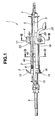
- the steering column 1 comprises a jacket tube 3 which is provided at its longitudinal central section with an upper bracket 4 and at its lower end section with a lower bracket 2.
- a steering shaft 5 is disposed inside the jacket tube 3 in a manner to extend along the axis of the jacket tube 3.
- a steering wheel (not shown) is connected to an upper end section of the steering shaft 5.
- An intermediate shaft 6 to be connected to a steering gear unit (not shown) is connected through a universal joint type coupling (not identified) to a lower end section of the steering shaft 5.
- a bearing 7 is fixed inside the upper end section of the jacket tube 3.
- the lower end section of the jacket tube 3 is bulged so as to be increased in inner diameter.
- a bearing 8 is disposed inside the jacket tube 3 at a position immediately above the bulged lower end section.
- the steering shaft 5 is rotatably supported by the bearings 7, 8 which are separate from each other.
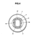
- the steering shaft 5 includes an upper shaft 9 which has a lower portion which has an inner peripheral surface which is generally oval in cross-section as seen in Fig. 4.
- the upper end section of the upper shaft 9 projects from the upper end of the jacket tube 3.
- the steering shaft 5 further includes a lower shaft 10 which is aligned with the upper shaft 9 and has a generally oval cross-section in its outer peripheral surface as seen in Fig. 4.
- the upper end section of the lower shaft 10 is fitted into the lower end section of the upper shaft 9 throughout a predetermined length thereby constituting a fitting connection part (no numeral).
- the lower shaft 10 is formed at its outer peripheral surface with peripheral grooves 40, 40, while the upper shaft 9 is formed with small through-holes 9a, 9a each of which is axially coincident with each of the peripheral groove 40, as shown in Fig. 4.
- a resin or plastic R is filled through the small through-holes 9a, 9a of the upper shaft 9 into the peripheral grooves 40, 40 of the lower shaft 10, so that the upper shaft 9 and the lower shaft 10 are fixed integral with each other when the resin is solidified in the state shown in Fig. 4.
- the lower bracket 2 is formed of a steel plate or sheet and has a large opening 12 in which the jacket tube 3 is disposed or loosely fitted in a manner to extend through the steel plate to form a generally crescentic space between the outer periphery of the jacket tube 3 and the inner periphery of the lower bracket 2 which periphery defines the opening 12.
- the steel plate of the upper peripheral section of the lower bracket 2 is bent to be inclined rearward to form a body installation section 14 to be connected to a vehicle body (not shown).
- the body installation section 14 is provided at its left- and right-side end sections with reinforcement flanges 13, 13 each of which is formed by bending the left- or right-side end section at right angles, so that each reinforcement flange 13 is perpendicular to the main body of the steel plate.
- the jacket tube 3 is welded at its outer peripheral surface with an inner peripheral section of the lower bracket 2 defining the opening 12 in such a manner that the jacket tube 3 is perpendicular to the main body of the steel plate of the lower bracket 2.
- a part of a lower peripheral section 15 of the steel plate of the lower bracket 2 is bent upwardly at right angles to form a reinforcement flange 16 which is located below the inner peripheral section at which the jacket tube 3 is welded.
- the intermediate side sections 11 of the steel plate of the lower bracket 2 is able to make its elastic bending deformation so as to cope with a tilt operation of the steering column 1.
- the intermediate side sections deform to be slightly bent to allow the tilt movement of the steering column 1.
- a tilting angle of the steering column 1 is not so large while the lower bracket 2 is elastically deformable, and therefore no breakage will occur in the lower bracket 2.
- the upper bracket 4 is formed of a steel plate or sheet and includes a body installation section 17 which is connected to the vehicle body.
- Front wall or support sections 18, 18 extend from the opposite sides (the right and left side portions F, F) of the front portion of the body installation section 17 in such a manner as to be perpendicular to the installation section 17.
- Column installation sections 19, 19 extend respectively from the inside portions of the front wall sections 18, 18 and perpendicular to the front wall sections 18, 18 or in a direction along the axis of the jacket tube 3, in which the jacket tube 3 is located between the opposite column installation sections 19, 19.
- the body installation section 17, the wall sections 18, 18 and the column installation sections 19, 19 are formed integral with each other to form a one-piece structure.
- a smooth or rounded bent section 20 is formed between each side portion F of the installation section 17 and each front wall section 18 as shown in Fig. 1, in which the bent section 20 has a predetermined curvature.
- the bent section 20 can be deformed under a load over a predetermined level.
- a clearance ⁇ is formed between the installation section 17 and the upper end edge of each column installation section 19 as shown in Figs. 1 and 3.
- the column installation sections 19, 19 are formed respectively with elongate tilt openings 21, 21 which extend generally vertically.
- a tilt bolt 22 is passed through these tilt openings 21, 21 and has a head section 22a at which a stopper 23 is secured with a nut 23a.
- the tile bolt 22 has a threaded section 22b which are located generally opposite to the head section 22a.
- a tilt nut 24 is engaged with the threaded section 22b and fixed to a tilt lever 25.
- a stopper 26 is mounted on the tilt bolt 22 and interposed between the tilt nut 24 and the column installation section 19.
- Each of the stoppers 23, 26 has a bent end portion 30 which is formed by bending the tip end portion of the stopper at right angles.
- a distance bracket 27 having a generally C-shaped cross-section is welded to the lower surface of the jacket tube 3.
- the distance bracket 27 has generally parallel side wall sections 27a, 27a which are connected with each other by a floor wall section 27b, in which the side wall sections 27a, 27a are welded to the lower surface of the jacket tube 3.
- the distance bracket 27 is disposed between the column installation sections 19, 19 in such a manner that the side wall sections 27a, 27a are respectively in contact with the column installation sections 19, 19.
- the side wall sections 27a, 27a are formed respectively with elongate through-holes 28, 28 each of which has a predetermined length and has first and second opposite rounded ends 28a, 28b.
- the first rounded end 28a is positioned forward relative to the second rounded end 28b in a fore-and-aft direction of a vehicle body (not shown) of the automotive vehicle.
- the tilt bolt 22 is passed through these elongate through-holes 28, 28 as show in Figs. 3, 5 and 6, while the tilt bolt is passed through the tilt openings 21, 21 so that the distance bracket 27 is generally vertically movable, constituting a tilt mechanism of the steering column 1.
- Each elongate through-hole 28 has an axis (not shown) which inclines relative to an axis C of the steering column 1 or of the steering shaft 5 in such a manner that the first rounded end 28a is positioned above relative to the second rounded end 28b with respect to the steering column axis C.
- each elongate through-hole 28 inclines forward in the fore-and-aft direction of the vehicle body relative to a direction perpendicular to the steering column axis C, in which the first rounded end 28a located on the frontward side of the vehicle body is located above the second rounded end 28b located on the rearward side of the vehicle body.
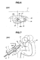
- the tilt bolt 22 can move in each elongate through-hole 28 along the axis of the elongate through-hole 28 under the action of a component force F2 of an impact load F 0 , so that the jacket tube 3 of the steering column 1 can move to the frontward side of the vehicle body.
- the movement of the jacket tube 3 in the axial direction of the steering column 1 is made by virtue of the arrangement in which the axis of each elongate through-hole 28 inclines forward in the fore-and-aft direction of the vehicle body relative to the direction perpendicular to the steering column axis C.
- the tilt bolt 22 is normally positioned close to or contacting with the first rounded end 28a on the frontward side of the vehicle body.
- the bent end portion 30 of the stopper 23 is inserted and engaged with a rectangular opening 29 formed in the side wall section 27a of the distance bracket 27.
- the bent end portion 30 of the stopper 26 is similarly inserted and engaged with a rectangular opening 29 formed in the other side wall section 27a.
- the tilt bolt 22 is normally positioned close to or contacting the first rounded end 28a located closer to the steering column axis C than the second rounded end 28b. Accordingly, the tilt bolt 22 is normally fixed at a predetermined position relative to the distance bracket 27, and therefore no trouble occurs when a tilt of the steering column 1 is set.
- the tilt lever 25 When the tilt lever 25 is turned downward to rotate the tilt nut 24, a tightening action of the column installation sections 19, 19 to the distance bracket 27 under the action of the tilt nut 24 and the head section 22a of the tilt bolt 22 is loosened, and therefore the distance bracket 27 becomes movable in both the generally upward and downward directions. Then, the jacket tube 3 is tilted through the steering wheel to take a desired inclined state, in which the jacket tube 3 can be rotationally moved generally vertically around a position at which the jacket tube 3 is welded to the inner peripheral section of the steel plate of the lower bracket 2. It will be understood that the lower bracket 2 is prevented from being broken because the maximum angle of tilting of the jacket tube 3 is small while the lower bracket 2 makes its elastic deformation.
- the jacket tube 3 is locked to keep the above inclined or tilted state.
- the distance bracket 27 is put between the column installation sections 19, 19 under pressure developed between the head section 22a of the tilt bolt 22 and the tilt nut 24.
- the distance bracket 27 is fixed between the column installation sections 19, 19 under friction.
- the front-side parts of the vehicle body move rearward, and therefore the jacket tube 3 is moved rearward in the vehicle body.
- the front wall sections 18, 18 of the upper bracket 4 are pushed rearward so that the upper end edge of the column installation sections 19, 19 moves toward the installation section 17 reducing the clearance ⁇ and finally comes into contact with the lower surface of the installation section 17.
- a rearward movement of the jacket tube 3 is stopped.
- the distance bracket 27 moves from the upper rounded end 28a to the lower rounded end 28b of the elongate through-hole 28 as shown in Fig. 9, in which the upper shaft 9 is forced to the lower shaft 10 by a moving amount D of the distance bracket 27 in the direction of the steering column axis C so that the resin R filled in the small through-holes 9a of the upper shaft 9 is sheared.
- the bent end portions 30, 30 of the stoppers 23, 26 come out of the rectangular openings 29, 29 of the distance bracket 27 or deform so as to allow the jacket tube 3 to move downward.
- the steering column of the above embodiment has been shown and described as being provided with a tilt mechanism by which the steering wheel is vertically adjustable, it will be understood that the principle of the above described teaching may applied to steering columns provided with no tilt mechanism.
- the tilt through-holes 21 of the upper bracket 4 are formed circular so as to prevent the tilt bolt 22 from moving relative to the upper bracket 4.
- the steering shaft in the secondary collision of the vehicle collision, can be moved forward with respect to the vehicle body by utilizing the inclined elongate through-hole through which the tilt bolt is passed. Consequently, the resin (as a part of an energy absorbing structure) in the axial connection between the upper and lower shafts 9, 10 of the steering shaft 5 is sheared to break the connection, before another energy absorbing structure formed in the upper bracket functions to exhibit its energy absorbing action.
- a time lag is produced between the actions of the two separate energy absorbing structures in the steering column 1, thereby suppressing at a low value the initial load in the secondary collision of the vehicle collision.
Landscapes
- Engineering & Computer Science (AREA)
- Chemical & Material Sciences (AREA)
- Combustion & Propulsion (AREA)
- Transportation (AREA)
- Mechanical Engineering (AREA)
- Steering Controls (AREA)
Claims (4)
- Lenksäule für ein Kraftfahrzeug, mit:dadurch gekennzeichnet, dasseinem Mantelrohr (3)einer Lenkwelle (5), drehbar durch Lager (7, 8) innerhalb des Mantelrohres (3) angeordnet, wobei die Lenkwelle (5) obere und unter Wellen (9, 10) enthält, die miteinander durch eine Verbindung, die Kunststoff (R ) verwendet, verbunden sind, wobei der Kunststoff in der Lage ist, durch eine axiale Belastung über ein vorbestimmtes Niveau, abgeschert zu werden, um eine axiale, relative Bewegung zwischen den oberen und den unteren Wellen (9, 10) zu gestatten;einem oberen Halter (4), fest an einer Fahrzeugkarosserie des Kraftfahrzeuges gelagert und der eine Öffnung (21) hat, wobei der obere Halter (4) einen energieaufnehmenden Aufbau zum Absorbierung einer Energie in einer axialen Richtung der Lenkwelle (5) hat;einem Abstandshalter (27), der fest einen Teil des Mantelrohres (3) lagert, wobei der Abstandshalter (27) mit einer Bohrung (28) gebildet ist; und einer Schraube (22), die durch die Öffnung (21) des oberen Halters (4) und die Bohrung (28) des Abstandshalters (27) durchgeht, um den Abstandshalter (27) an dem oberen Halter (4) zu befestigen,
die Bohrung des Abstandshalters (27) ein Langloch (28) ist, das eine vorbestimmte Länge hat und das eine Achse hat, die sich relativ zu einer Achse (C) der Lenkwelle (%) neigt, wobei das Langloch (28) ein erstes Ende (28a) und ein zweites Ende (28b) hat, in Bezug auf die Fahrzeugkarosserie hinter dem ersten Ende (28a) angeordnet ist, wobei das erste Ende (28a) näher zu der Achse (C) der Lenkwelle (5) als das zweite Ende (28b) angeordnet ist; und
die Schraube (22) normalerweise näher zu dem ersten Ende (28a) als zu dem zweiten Ende (28b) des Langloches (28) angeordnet ist. - Lenksäule nach Anspruch 1, gekennzeichnet durch einen Anschlag (23, 26) zum normalen Befestigen der Schraube (22) an einer Position, die näher zu dem ersten Ende (28a) als zu dem zweiten Ende (28b) des Langloches (28) ist, wobei der Anschlag (23, 26) fest zwischen der Schraube (22) und einem Teil des Abstandshalters (27) eingesetzt ist, wobei der Anschlag (23, 26) verformbar ist, wenn die axiale Belastung auf ihn einwirkt.
- Lenksäule nach Anspruch 1 oder 2, dadurch gekennzeichnet, dass die Schraube (22) im Querschnitt kreisförmig ist, wobei jedes der ersten und der zweiten Enden (28a, 28b) des Langloches des Abstandshalters (27) abgerundet gebildet ist, um eine halbkreisförmige Form anzunehmen.
- Lenksäule nach zumindest einem der Ansprüche 1 bis 3, dadurch gekennzeichnet, dass der obere Halter (4) im Wesentlichen parallele erste und zweite Lagerabschnitte (19) enthält, die bei der Aufnahme einer Energie in einer axialen Richtung der Lenkwelle (5) bewegbar sind, um die Energie aufzunehmen, wobei in dem ersten und dem zweiten Lagerabschnitt (19) jeweils eine erste und eine zweite Öffnung (21) des oberen Halters (4) vorgesehen ist;
wobei der Abstandshalter (27) im Wesentlichen parallele erste und zweite Seitenwandabschnitte (27a) enthält, zwischen denen der Teil des Mantelrohres (3) fest gelagert ist, wobei die ersten und die zweiten Seitenwandabschnitte (27a) zwischen den ersten und den zweiten Lagerabschnitten (19) des oberen Halters (4) angeordnet sind, wobei jeweils ein erstes und ein zweites Langloch (28) in dem ersten und zweiten Wandabschnitt (27a) vorgesehen ist, wobei jedes der Langlöcher (28) die vorbestimmte Länge hat und eine Achse hat, die sich im Verhältnis zu der Achse (C ) der Steuerwelle (5) neigt, wobei die Schraube (22) durch die erste und die zweite Öffnung (21) des oberen Halters (4) und das erste und zweite Langloch (28) des Abstandshalters (27) hindurchgeht, um den Abstandshalter (27) an dem oberen Halter (4) zu befestigen.
Applications Claiming Priority (2)
| Application Number | Priority Date | Filing Date | Title |
|---|---|---|---|
| JP35866997 | 1997-12-26 | ||
| JP35866997A JP3396158B2 (ja) | 1997-12-26 | 1997-12-26 | ステアリングコラムのエネルギー吸収構造 |
Publications (3)
| Publication Number | Publication Date |
|---|---|
| EP0928733A2 EP0928733A2 (de) | 1999-07-14 |
| EP0928733A3 EP0928733A3 (de) | 2000-10-11 |
| EP0928733B1 true EP0928733B1 (de) | 2003-07-02 |
Family
ID=18460513
Family Applications (1)
| Application Number | Title | Priority Date | Filing Date |
|---|---|---|---|
| EP98124084A Expired - Lifetime EP0928733B1 (de) | 1997-12-26 | 1998-12-18 | Lenksäule für ein Kraftfahrzeug |
Country Status (4)
| Country | Link |
|---|---|
| US (1) | US6148687A (de) |
| EP (1) | EP0928733B1 (de) |
| JP (1) | JP3396158B2 (de) |
| DE (1) | DE69816022T2 (de) |
Families Citing this family (10)
| Publication number | Priority date | Publication date | Assignee | Title |
|---|---|---|---|---|
| US6398259B1 (en) | 2001-04-18 | 2002-06-04 | Bayer Corporation | Break-away bracket |
| US6708583B2 (en) | 2001-04-18 | 2004-03-23 | Bayer Polymers Llc | Shaft support structure |
| JP2003127874A (ja) | 2001-10-23 | 2003-05-08 | Fuji Kiko Co Ltd | 衝撃吸収式チルトステアリングコラム |
| AU2003246136A1 (en) * | 2002-07-02 | 2004-01-23 | Nsk Ltd. | Shock absorbing steering column device for vehicle |
| JP4179049B2 (ja) * | 2002-07-16 | 2008-11-12 | 日本精工株式会社 | 位置調整式ステアリングコラム装置 |
| US7125048B2 (en) * | 2002-11-06 | 2006-10-24 | Lear Corporation | Dampener |
| US6830516B2 (en) * | 2003-04-01 | 2004-12-14 | The Torrington Company | Ball hub apparatus and method for use in a universal joint |
| US7408708B2 (en) * | 2004-04-16 | 2008-08-05 | Dai Nippon Printing Co., Ltd. | Diffusing sheet, surface light source unit, and transmission type display |
| US7272989B2 (en) * | 2005-04-21 | 2007-09-25 | Paccar Inc | Steering shaft bearing assembly |
| US7497470B2 (en) * | 2005-11-21 | 2009-03-03 | Delphi Technologies, Inc. | Energy absorbing apparatus |
Family Cites Families (8)
| Publication number | Priority date | Publication date | Assignee | Title |
|---|---|---|---|---|
| JP2513589Y2 (ja) * | 1990-07-05 | 1996-10-09 | 日本精工株式会社 | ステアリング装置用コラプシブルシャフトの連結部 |
| US5181435A (en) * | 1992-03-30 | 1993-01-26 | Chrysler Corp | Steering column guide assembly |
| JP2935950B2 (ja) * | 1993-12-03 | 1999-08-16 | 株式会社山田製作所 | ステアリングシャフト及びその製造装置 |
| JPH08150943A (ja) * | 1994-11-30 | 1996-06-11 | Fuji Kiko Co Ltd | チルトステアリングコラム |
| JP3415953B2 (ja) * | 1995-02-03 | 2003-06-09 | 日本精工株式会社 | ステアリングコラムの支持装置 |
| EP0769444B1 (de) * | 1995-10-20 | 1998-09-16 | Fuji Kiko Co., Ltd. | Lenksäule für ein Kraftfahrzeug |
| FR2748250B1 (fr) * | 1996-05-03 | 1998-06-26 | Lemforder Nacam Sa | Dispositif de positionnement, lors d'un choc, d'une colonne de direction de vehicule automobile |
| JPH10114271A (ja) * | 1996-10-11 | 1998-05-06 | Honda Motor Co Ltd | チルト式ステアリング装置 |
-
1997
- 1997-12-26 JP JP35866997A patent/JP3396158B2/ja not_active Expired - Fee Related
-
1998
- 1998-12-18 DE DE69816022T patent/DE69816022T2/de not_active Expired - Lifetime
- 1998-12-18 EP EP98124084A patent/EP0928733B1/de not_active Expired - Lifetime
- 1998-12-21 US US09/216,827 patent/US6148687A/en not_active Expired - Fee Related
Also Published As
| Publication number | Publication date |
|---|---|
| EP0928733A2 (de) | 1999-07-14 |
| EP0928733A3 (de) | 2000-10-11 |
| DE69816022D1 (de) | 2003-08-07 |
| JPH11189164A (ja) | 1999-07-13 |
| JP3396158B2 (ja) | 2003-04-14 |
| DE69816022T2 (de) | 2004-01-29 |
| US6148687A (en) | 2000-11-21 |
Similar Documents
| Publication | Publication Date | Title |
|---|---|---|
| US5503431A (en) | Adjustable energy absorbing steering column with adjustment disabled during collision | |
| US6623036B2 (en) | Steering column assembly for a vehicle | |
| US7798525B2 (en) | Collapsible steering column assembly | |
| EP1693280B1 (de) | Sicherheitsvorrichtung für eine Lenkanordnung | |
| US5875686A (en) | Steering column for automotive vehicle | |
| CN102438878A (zh) | 冲击吸收式转向装置 | |
| EP1245472A2 (de) | Lenkeinrichtung | |
| EP1518775B1 (de) | Stossabsorbierende lenksäulenvorrichtung für fahrzeug | |
| EP0928733B1 (de) | Lenksäule für ein Kraftfahrzeug | |
| EP0448246B1 (de) | Aufbau einer Lenksäule | |
| US4998999A (en) | Steering column assembly with energy absorption mechanism | |
| JP2000006819A (ja) | 衝撃吸収式ステアリングコラムの支持装置 | |
| US5209135A (en) | Impact absorbing type steering column device | |
| US7125046B2 (en) | Shock absorbing steering column device for vehicle | |
| EP3696052B1 (de) | Lenksäulenvorrichtung | |
| EP0581432B1 (de) | Aufprallabsorbierende Lenksäule mit Servolenkeinrichtung | |
| JP2978788B2 (ja) | 自動車用ステアリングコラム | |
| US5737970A (en) | Safety steering column for a motor vehicle | |
| JPH09193812A (ja) | 衝撃吸収式ステアリングコラム装置 | |
| JP3409634B2 (ja) | 電動パワーステアリング装置付衝撃吸収式ステアリング装置 | |
| EP0919453B1 (de) | Schockabsorbierendes Rahmenelement für Fahrzeuge | |
| KR100820007B1 (ko) | 자동차용 스티어링 칼럼의 충격흡수 구조 | |
| JP3070445B2 (ja) | 衝撃吸収式ステアリング装置 | |
| JP2008260358A (ja) | 衝撃吸収式ステアリングコラム装置 | |
| KR200301922Y1 (ko) | 자동차용 스티어링 칼럼의 충격흡수장치 |
Legal Events
| Date | Code | Title | Description |
|---|---|---|---|
| PUAI | Public reference made under article 153(3) epc to a published international application that has entered the european phase |
Free format text: ORIGINAL CODE: 0009012 |
|
| 17P | Request for examination filed |
Effective date: 19981218 |
|
| AK | Designated contracting states |
Kind code of ref document: A2 Designated state(s): DE FR GB |
|
| AX | Request for extension of the european patent |
Free format text: AL;LT;LV;MK;RO;SI |
|
| PUAL | Search report despatched |
Free format text: ORIGINAL CODE: 0009013 |
|
| AK | Designated contracting states |
Kind code of ref document: A3 Designated state(s): AT BE CH CY DE DK ES FI FR GB GR IE IT LI LU MC NL PT SE |
|
| AX | Request for extension of the european patent |
Free format text: AL;LT;LV;MK;RO;SI |
|
| AKX | Designation fees paid |
Free format text: DE FR GB |
|
| 17Q | First examination report despatched |
Effective date: 20020425 |
|
| GRAH | Despatch of communication of intention to grant a patent |
Free format text: ORIGINAL CODE: EPIDOS IGRA |
|
| GRAH | Despatch of communication of intention to grant a patent |
Free format text: ORIGINAL CODE: EPIDOS IGRA |
|
| GRAA | (expected) grant |
Free format text: ORIGINAL CODE: 0009210 |
|
| AK | Designated contracting states |
Designated state(s): DE FR GB |
|
| REG | Reference to a national code |
Ref country code: GB Ref legal event code: FG4D |
|
| REF | Corresponds to: |
Ref document number: 69816022 Country of ref document: DE Date of ref document: 20030807 Kind code of ref document: P |
|
| ET | Fr: translation filed | ||
| PLBE | No opposition filed within time limit |
Free format text: ORIGINAL CODE: 0009261 |
|
| STAA | Information on the status of an ep patent application or granted ep patent |
Free format text: STATUS: NO OPPOSITION FILED WITHIN TIME LIMIT |
|
| 26N | No opposition filed |
Effective date: 20040405 |
|
| PGFP | Annual fee paid to national office [announced via postgrant information from national office to epo] |
Ref country code: GB Payment date: 20131224 Year of fee payment: 16 |
|
| PGFP | Annual fee paid to national office [announced via postgrant information from national office to epo] |
Ref country code: DE Payment date: 20131223 Year of fee payment: 16 |
|
| PGFP | Annual fee paid to national office [announced via postgrant information from national office to epo] |
Ref country code: FR Payment date: 20131220 Year of fee payment: 16 |
|
| REG | Reference to a national code |
Ref country code: DE Ref legal event code: R119 Ref document number: 69816022 Country of ref document: DE |
|
| GBPC | Gb: european patent ceased through non-payment of renewal fee |
Effective date: 20141218 |
|
| REG | Reference to a national code |
Ref country code: FR Ref legal event code: ST Effective date: 20150831 |
|
| PG25 | Lapsed in a contracting state [announced via postgrant information from national office to epo] |
Ref country code: DE Free format text: LAPSE BECAUSE OF NON-PAYMENT OF DUE FEES Effective date: 20150701 Ref country code: GB Free format text: LAPSE BECAUSE OF NON-PAYMENT OF DUE FEES Effective date: 20141218 |
|
| PG25 | Lapsed in a contracting state [announced via postgrant information from national office to epo] |
Ref country code: FR Free format text: LAPSE BECAUSE OF NON-PAYMENT OF DUE FEES Effective date: 20141231 |