US6830516B2 - Ball hub apparatus and method for use in a universal joint - Google Patents
Ball hub apparatus and method for use in a universal joint Download PDFInfo
- Publication number
- US6830516B2 US6830516B2 US10/404,639 US40463903A US6830516B2 US 6830516 B2 US6830516 B2 US 6830516B2 US 40463903 A US40463903 A US 40463903A US 6830516 B2 US6830516 B2 US 6830516B2
- Authority
- US
- United States
- Prior art keywords
- flat areas
- exterior
- bushing
- interior
- disposed
- Prior art date
- Legal status (The legal status is an assumption and is not a legal conclusion. Google has not performed a legal analysis and makes no representation as to the accuracy of the status listed.)
- Expired - Fee Related
Links
Images


Classifications
-
- F—MECHANICAL ENGINEERING; LIGHTING; HEATING; WEAPONS; BLASTING
- F16—ENGINEERING ELEMENTS AND UNITS; GENERAL MEASURES FOR PRODUCING AND MAINTAINING EFFECTIVE FUNCTIONING OF MACHINES OR INSTALLATIONS; THERMAL INSULATION IN GENERAL
- F16D—COUPLINGS FOR TRANSMITTING ROTATION; CLUTCHES; BRAKES
- F16D3/00—Yielding couplings, i.e. with means permitting movement between the connected parts during the drive
- F16D3/16—Universal joints in which flexibility is produced by means of pivots or sliding or rolling connecting parts
- F16D3/26—Hooke's joints or other joints with an equivalent intermediate member to which each coupling part is pivotally or slidably connected
- F16D3/38—Hooke's joints or other joints with an equivalent intermediate member to which each coupling part is pivotally or slidably connected with a single intermediate member with trunnions or bearings arranged on two axes perpendicular to one another
- F16D3/42—Hooke's joints or other joints with an equivalent intermediate member to which each coupling part is pivotally or slidably connected with a single intermediate member with trunnions or bearings arranged on two axes perpendicular to one another with ring-shaped intermediate member provided with bearings or inwardly-directed trunnions
-
- Y—GENERAL TAGGING OF NEW TECHNOLOGICAL DEVELOPMENTS; GENERAL TAGGING OF CROSS-SECTIONAL TECHNOLOGIES SPANNING OVER SEVERAL SECTIONS OF THE IPC; TECHNICAL SUBJECTS COVERED BY FORMER USPC CROSS-REFERENCE ART COLLECTIONS [XRACs] AND DIGESTS
- Y10—TECHNICAL SUBJECTS COVERED BY FORMER USPC
- Y10T—TECHNICAL SUBJECTS COVERED BY FORMER US CLASSIFICATION
- Y10T29/00—Metal working
- Y10T29/49—Method of mechanical manufacture
- Y10T29/49636—Process for making bearing or component thereof
- Y10T29/49696—Mounting
Definitions
- the invention relates generally to universal joints. More specifically, embodiments of the invention relate to ball hubs for use in universal joints and methods of manufacture.
- the steering system generally includes a common shaft, supported by a steering column, coupling a steering wheel to a steering gear assembly for transmitting directional rotation from a user to a steering geometry to provide directional control.
- the shaft typically passes through a vehicle firewall that separates passenger and engine compartments.
- the shaft has to navigate a complicated route necessitating two or more joints that connect the rotating shafts allowing for freedom of rotation regardless of the different angles the steering shaft experiences.
- a Cardan, or yoke type universal joint is frequently used to accomplish the transitions between steering shaft angles.
- This type of universal joint is common in the industry and includes two yokes and a cross shaft. Bearing surfaces couple the cross shaft to the yokes, allowing for a predetermined freedom of movement in two planes.
- This type of universal joint includes a first shaft 17 having at one end a ball hub 19 , that is usually attached with a long pin 21 allowing for a first axis of pivotal motion.
- the long pin 21 passes through one side of the ball hub 19 along an equator, through the first shaft 17 , and back into the ball 19 .
- the ball 19 is received in a cup 23 that is rigidly attached to a second shaft 25 .
- the ball hub 19 is retained in the cup 23 using two short pins 27 , 27 ′ that allow for a second axis of pivotal motion orthogonal to the first axis.
- Each short pin 27 , 27 ′ passes through the outside of the cup 23 and into the ball 19 along the equator.
- the ball hub and cup can be made from self-lubricating plastics such as Teflon®, Delrin®, or others, thereby obviating the need for low friction bearing surfaces between the moving parts (pins, ball and cup).
- self-lubricating plastics such as Teflon®, Delrin®, or others.
- metal offers greater robustness and durability than most self-lubricating plastics.
- the metal parts need low friction load bearing surfaces.
- bushings are placed into the ball hub 19 pin holes where the long pin 21 and short pins 27 , 27 ′ couple the first shaft 17 to the ball hub 19 and to the cup 23 as shown in FIG. 3 .
- the bushings are typically made of a self-lubricating material.
- Each bushing has an associated flange surface to minimize friction between surfaces of the first shaft 17 and ball hub 19 , and the ball hub 19 and cup 23 .
- the long pin 21 bushings 29 , 29 ′ locate their flange surfaces 33 , 33 ′ on the interior of the ball hub 19
- the short pin 27 , 27 ′ bushings 31 , 31 ′ locate their flange surfaces 35 , 35 ′ on the exterior of the ball hub 19 .
- bushing inserts solve one problem, they create a problem of their own.
- the allowable rotational lash or play between the first and second shafts may be specified at a minimum. Precise, low clearance fits would therefore be required between the long 21 and short 27 , 27 ′ pins and ball hub 19 to meet the lash specification of the steering shaft.
- a bushing is a removable cylindrical guide, where one low clearance fit existed between the pin and mating surface, another low clearance fit between the bushing and mating surface is created.
- the clearance between the three components increases rotational lash above design specifications. Further, the bushings can rotate when the joint is being exercised causing binding of the joint. This in turn increases the torque necessary to rotate the shaft while concomitantly decreasing the joint articulation.
- the prior art has addressed this shortcoming by decreasing the internal diameter of the bushings such that the insertion of the pins causes the bushings to expand, reducing the clearance fit between the long 21 and short 27 , 27 ′ pins, bushings 29 , 29 ′, 31 , 31 ′ and ball hub 19 .
- insertion of the pins can shave the inner diameter of the bushings resulting in unacceptable lash.
- the bushings would not expand sufficiently to reduce clearance between the bushing and ball hub to achieve an acceptable lash.
- a universal joint hub comprising a generally spherical body having two flat areas on opposing exterior sides and at least one opening into an open body interior.
- the hub has two flat areas on opposing interior surfaces of the body orthogonal to the exterior flat areas and an exterior circumferential groove extending between the exterior flat areas on a given plane.
- Four apertures extend into the body and are positioned orthogonal to each other on the given plane with each aperture disposed in one of the flat areas.
- a bushing is disposed in each aperture having a face exposed to the exterior surface.
- a circumferential band is disposed in the circumferential groove coupling each of the bushings.
- the method begins with forming a generally spherical body having two flat areas on opposing exterior sides and at least one opening into an open body interior. Forming two flat areas on opposing interior surfaces of the body, the interior flat areas orthogonal to the exterior flat areas. Forming an exterior circumferential groove extending between the exterior flat areas on a given plane and creating four apertures extending into the body and positioned orthogonal to each other on the given plane with each aperture disposed in one of the flat areas. Disposing a bushing in each of the apertures, each bushing having a face exposed to the exterior surface and disposing a circumferential band in the circumferential groove thereby coupling each of the bushings.
- FIG. 1 is an exploded view of a prior art ball hub universal joint.
- FIG. 2 is an opposing view of the prior art ball hub shown in FIG. 1 .
- FIG. 3 is an isometric projection of the prior art ball hub shown in FIG. 1 .
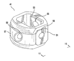
- FIG. 4 is an isometric projection of an exemplary ball hub with groove in accordance with one embodiment of the invention.
- FIGS. 5 a and 5 b are exemplary views of a long pin bushing.
- FIGS. 6 a and 6 b are exemplary views of a short pin bushing.
- FIGS. 7 a and 7 b are exemplary views of an alternative long pin bushing.
- FIGS. 8 a and 8 b are exemplary views of an alternative short pin bushing.
- FIG. 9 is a view along line 9 — 9 in FIG. 4 with bushings and circumferential band.
- FIG. 10 is a view along line 10 — 10 in FIG. 9 .
- FIG. 11 is an isometric projection of an exemplary ball hub in accordance with another embodiment of the invention.
- FIG. 12 is a view along line 12 — 12 in FIG. 11 with bushings.
- a hollow, spherical hub 41 is provided.
- a groove 37 having a predetermined depth and width is positioned on the outer surface along an equatorial plane 47 of the hub as shown in FIG. 4.
- a cup (not shown) of matching correspondence receives the hub 41 .
- the invention can replace a preexisting, prior art ball hub design.
- the hub 41 and cup are not limited by size.
- the hub 41 is a hollow, generally spherical section that can be metal, an alloy, ceramic or other material composition.
- the hub 41 has one or more openings 44 to the interior 46 .
- the opening 44 and interior 46 are configured to receive the shaft 17 .
- Four holes are provided through the hub 41 into the interior 46 for receiving the long 21 and short 27 , 27 ′ pins.
- Two short pin holes 43 , 43 ′ and two long pin holes 45 , 45 ′ are positioned orthogonal to each other along an equatorial plane 47 , with associated pin holes sharing the same axis of rotation 180° apart.
- the short pin holes 43 , 43 ′ are located on exterior flats 49 , 49 ′, and the long pin holes 45 , 45 ′ are positioned in the groove 37 .
- Each hole 43 , 43 ′, 45 , 45 ′ receives a self-lubricating bushing 51 , 53 , as shown in FIGS. 5-8, that extends from the ball hub 41 exterior surface to the interior surface.
- the inner diameter for all bushings 51 , 53 are molded smaller than the long 21 and short pin 27 , 27 ′ outer diameters to create an interference fit between the outer diameter of the pins 21 , 27 , 27 ′ and the inner diameter of the bushings 51 , 53 .
- Stress-relieving slots 55 are molded into the bushings along the axial length of the bushing 51 , 53 and radially, on an associated flange surface 33 , 33 ′, 35 , 35 ′ having a predetermined surface area and configuration, in a substantially vertical axis alignment, thereby providing a slot running the length of the bushing to the edge of the flange surface.
- the flange surfaces can be of any configuration and thickness.
- the slots 55 have a predetermined depth and width depending upon the long 21 and short 27 , 27 ′ pin dimensions (O.D. and length) and the desired thickness of the bushing ( O . D . - I . D . 2 ) .
- the rotational load placed on the long 21 and short pins 27 , 27 ′, and bushings 51 , 53 is confined to the equatorial plane 47 .
- Positioning the stress relieving slots 55 in the vertical axis effectively removes the slot 55 from any load.
- the stress relieving slot 55 can be located on the inner diameter of a bushing 55 and outer surface of the associated flange surface 33 , 35 as shown in FIGS. 5 and 6, or, on the outer diameter and inner surface of the flange 33 , 35 as shown in FIGS. 7 and 8.
- the stress relieving slots 55 allow each bushing 51 , 53 to expand, filling the clearance between the bushings and ball hub 41 as described below.
- a circumferential band 57 of a compatible material or the same material comprising the bushings 51 , 53 is applied in the groove 37 , by molding or other means, coupling together the four bushings 51 , 53 as one assembly and forming a continuous ring around the circumference, or equatorial plane 47 of the ball hub 41 . Since the circumferential area of the band 57 is greater than that of the exposed, exterior bushing 51 , 53 areas, contraction or shrinkage of the band 57 after application exceeds the strength of the stress relieving slots 55 causing them to either partially or completely fracture, and thereby open as shown in FIGS. 9 and 10 with the bushing 51 , 53 embodiments shown in FIGS. 5 and 6.
- each bushing 51 , 53 is increased thereby allowing the pins 21 , 27 , 27 ′ to be inserted without shaving the bushing 51 , 53 . If a portion of a bushing 51 , 53 stress-relieving slot 55 did not fracture during circumferential band 57 contraction, pin insertion competes fracturing, reducing clearance between the ball hub, bushing and pin resulting in reduced lash.
- the circumferential band 57 additionally prohibits each bushing 51 , 53 from rotating eliminating torque to rotate and articulation issues. Additionally, the machining of the circumferential groove 37 around the ball hub 41 reduces the wall thickness in the areas where the long pin 21 holes are located, allowing the holes 45 , 45 ′ to be punched rather than drilled.
- FIGS. 11 and 12 Another embodiment of the invention is shown in FIGS. 11 and 12.
- a groove 65 having a predetermined depth, length and cross-section is broached along the interior flats of the ball hub 61 radial to the long pin 21 holes on the long pin axis.
- a groove 63 having a predetermined depth, length and cross-section is broached radial to the short pin 27 , 27 ′ holes on the short pin axis.
- the groove 63 , 65 cross-section can be rectangular, dovetail or others.
- the groove 63 , 65 can be at any angle with respect to the axis of rotation and length.
- Bushings 67 , 69 similar to those shown in FIGS.
Landscapes
- Engineering & Computer Science (AREA)
- General Engineering & Computer Science (AREA)
- Mechanical Engineering (AREA)
- Pivots And Pivotal Connections (AREA)
Abstract
Description

Claims (13)
Priority Applications (1)
| Application Number | Priority Date | Filing Date | Title |
|---|---|---|---|
| US10/404,639 US6830516B2 (en) | 2003-04-01 | 2003-04-01 | Ball hub apparatus and method for use in a universal joint |
Applications Claiming Priority (1)
| Application Number | Priority Date | Filing Date | Title |
|---|---|---|---|
| US10/404,639 US6830516B2 (en) | 2003-04-01 | 2003-04-01 | Ball hub apparatus and method for use in a universal joint |
Publications (2)
| Publication Number | Publication Date |
|---|---|
| US20040198500A1 US20040198500A1 (en) | 2004-10-07 |
| US6830516B2 true US6830516B2 (en) | 2004-12-14 |
Family
ID=33096959
Family Applications (1)
| Application Number | Title | Priority Date | Filing Date |
|---|---|---|---|
| US10/404,639 Expired - Fee Related US6830516B2 (en) | 2003-04-01 | 2003-04-01 | Ball hub apparatus and method for use in a universal joint |
Country Status (1)
| Country | Link |
|---|---|
| US (1) | US6830516B2 (en) |
Cited By (3)
| Publication number | Priority date | Publication date | Assignee | Title |
|---|---|---|---|---|
| US20070037172A1 (en) * | 2005-08-11 | 2007-02-15 | Chiu Daniel T | Separation and concentration of biological cells and biological particles using a one-dimensional channel |
| US8591136B2 (en) * | 2010-05-27 | 2013-11-26 | Agusta S.P.A. | Non-rotating universal joint for a helicopter drive unit |
| US9664237B2 (en) * | 2014-10-31 | 2017-05-30 | Steering Solutions Ip Holding Corporation | Sector journal bearing |
Citations (14)
| Publication number | Priority date | Publication date | Assignee | Title |
|---|---|---|---|---|
| US1121144A (en) * | 1914-12-15 | Ajax Universal Joint Company | Universal joint. | |
| US2153415A (en) * | 1937-10-20 | 1939-04-04 | Curtis Universal Joint Co Inc | Universal joint |
| US4365488A (en) * | 1979-05-11 | 1982-12-28 | Nissan Motor Co., Ltd. | Universal joint |
| US4384861A (en) | 1979-10-10 | 1983-05-24 | Firma LWM Lemforder Gelenkwellen GmbH | Universal joint shaft, particularly for a steering column of motor vehicles |
| US4636180A (en) | 1984-08-23 | 1987-01-13 | Allied Corporation | Universal joint with stationary seats |
| US5326322A (en) * | 1991-12-09 | 1994-07-05 | Weasler Engineering, Inc. | Cone style universal joint |
| US5358445A (en) | 1990-03-15 | 1994-10-25 | General Signal Corporation | Variable angle torque transmitting coupling device |
| US5423722A (en) | 1993-05-27 | 1995-06-13 | General Motors Corporation | A steering shaft |
| US5704641A (en) | 1994-11-30 | 1998-01-06 | Fuji Kiko Co., Ltd. | Position stopper of tilt steering column |
| US6019391A (en) | 1998-05-04 | 2000-02-01 | General Motors Corporation | Steering column for motor vehicle |
| US6099036A (en) | 1996-07-19 | 2000-08-08 | Kabushiki Kaisha Yamada Seisakusho | Intermediate shaft apparatus of steering shaft assembly |
| US6148687A (en) | 1997-12-26 | 2000-11-21 | Fuji Kiko Co., Ltd. | Steering column for automotive vehicle |
| US6293167B1 (en) | 1998-10-08 | 2001-09-25 | Imo Industries, Inc. | Universal joint for vehicle steering system |
| US6435555B1 (en) | 2000-02-10 | 2002-08-20 | Delphi Technologies, Inc. | Collapsible steering column and method |
-
2003
- 2003-04-01 US US10/404,639 patent/US6830516B2/en not_active Expired - Fee Related
Patent Citations (14)
| Publication number | Priority date | Publication date | Assignee | Title |
|---|---|---|---|---|
| US1121144A (en) * | 1914-12-15 | Ajax Universal Joint Company | Universal joint. | |
| US2153415A (en) * | 1937-10-20 | 1939-04-04 | Curtis Universal Joint Co Inc | Universal joint |
| US4365488A (en) * | 1979-05-11 | 1982-12-28 | Nissan Motor Co., Ltd. | Universal joint |
| US4384861A (en) | 1979-10-10 | 1983-05-24 | Firma LWM Lemforder Gelenkwellen GmbH | Universal joint shaft, particularly for a steering column of motor vehicles |
| US4636180A (en) | 1984-08-23 | 1987-01-13 | Allied Corporation | Universal joint with stationary seats |
| US5358445A (en) | 1990-03-15 | 1994-10-25 | General Signal Corporation | Variable angle torque transmitting coupling device |
| US5326322A (en) * | 1991-12-09 | 1994-07-05 | Weasler Engineering, Inc. | Cone style universal joint |
| US5423722A (en) | 1993-05-27 | 1995-06-13 | General Motors Corporation | A steering shaft |
| US5704641A (en) | 1994-11-30 | 1998-01-06 | Fuji Kiko Co., Ltd. | Position stopper of tilt steering column |
| US6099036A (en) | 1996-07-19 | 2000-08-08 | Kabushiki Kaisha Yamada Seisakusho | Intermediate shaft apparatus of steering shaft assembly |
| US6148687A (en) | 1997-12-26 | 2000-11-21 | Fuji Kiko Co., Ltd. | Steering column for automotive vehicle |
| US6019391A (en) | 1998-05-04 | 2000-02-01 | General Motors Corporation | Steering column for motor vehicle |
| US6293167B1 (en) | 1998-10-08 | 2001-09-25 | Imo Industries, Inc. | Universal joint for vehicle steering system |
| US6435555B1 (en) | 2000-02-10 | 2002-08-20 | Delphi Technologies, Inc. | Collapsible steering column and method |
Cited By (3)
| Publication number | Priority date | Publication date | Assignee | Title |
|---|---|---|---|---|
| US20070037172A1 (en) * | 2005-08-11 | 2007-02-15 | Chiu Daniel T | Separation and concentration of biological cells and biological particles using a one-dimensional channel |
| US8591136B2 (en) * | 2010-05-27 | 2013-11-26 | Agusta S.P.A. | Non-rotating universal joint for a helicopter drive unit |
| US9664237B2 (en) * | 2014-10-31 | 2017-05-30 | Steering Solutions Ip Holding Corporation | Sector journal bearing |
Also Published As
| Publication number | Publication date |
|---|---|
| US20040198500A1 (en) | 2004-10-07 |
Similar Documents
| Publication | Publication Date | Title |
|---|---|---|
| US7445556B2 (en) | Universal joint | |
| KR101024883B1 (en) | Tripod type constant velocity joint | |
| US6217456B1 (en) | Telescopic shaft | |
| US5062730A (en) | Universal joint | |
| JPH1130315A (en) | Differential unit with optimized assembly window geometry | |
| US6162126A (en) | Universal joint | |
| US6893350B2 (en) | Universal joint with torsionally-compliant spider assembly | |
| US8449399B2 (en) | Joint assembly with centering flange | |
| EP1469214B1 (en) | Universal joint | |
| US5728004A (en) | Universal joint with layered bushings | |
| US6830516B2 (en) | Ball hub apparatus and method for use in a universal joint | |
| US20080096678A1 (en) | Fixed Type Constant Velocity Joint | |
| EP1597489B1 (en) | Universal joint with retention mechanism | |
| JP2006524783A (en) | Centering device for centering the ends of two shafts together | |
| US6752721B2 (en) | Constant velocity universal joint | |
| US20050003896A1 (en) | Arrangement of a running roller on a coupling journal of a moveable shaft coupling | |
| US6846242B1 (en) | Universal joint assembly | |
| JP2002540357A (en) | Special strengthening system to accommodate universal joint bearings | |
| US8029373B2 (en) | Fixed constant velocity universal joint | |
| JPH08312662A (en) | Cardan type shaft coupling | |
| JP2002539382A (en) | Joint for connecting two rotatable shaft ends | |
| JP3919060B2 (en) | Universal joint | |
| US20170074381A1 (en) | Crowned profile driveshaft journal | |
| JPS646416Y2 (en) | ||
| CN117006167A (en) | Constant velocity joint with riveting characteristics |
Legal Events
| Date | Code | Title | Description |
|---|---|---|---|
| AS | Assignment |
Owner name: TORRINGTON COMPANY, THE, CONNECTICUT Free format text: ASSIGNMENT OF ASSIGNORS INTEREST;ASSIGNORS:MCCORMICK, CHRISTOPHER E.;FAPPIANO, NICHOLAS T.;REEL/FRAME:014213/0682 Effective date: 20030617 |
|
| AS | Assignment |
Owner name: WELLS FARGO FOOTHILL, INC., AS AGENT, GEORGIA Free format text: SECURITY AGREEMENT;ASSIGNOR:DRIVESOL GLOBAL STEERING, INC.;REEL/FRAME:018711/0480 Effective date: 20061218 |
|
| AS | Assignment |
Owner name: TIMKEN US CORPORATION, CONNECTICUT Free format text: CHANGE OF NAME;ASSIGNOR:THE TORRINGTON COMPANY;REEL/FRAME:018806/0522 Effective date: 20030218 Owner name: DRIVESOL GLOBAL STEERING, INC., MICHIGAN Free format text: ASSIGNMENT OF ASSIGNORS INTEREST;ASSIGNOR:TIMKEN US CORPORATION;REEL/FRAME:018806/0012 Effective date: 20061218 |
|
| FPAY | Fee payment |
Year of fee payment: 4 |
|
| REMI | Maintenance fee reminder mailed | ||
| AS | Assignment |
Owner name: SUN DRIVESOL FINANCE, LLC, FLORIDA Free format text: SECURITY AGREEMENT;ASSIGNORS:DRIVESOL INTERMEDIATE HOLDING CORP.;DRIVESOL WORLDWIDE, INC.;DRIVESOL AUTOMOTIVE INCORPORATED;AND OTHERS;REEL/FRAME:021158/0208 Effective date: 20080625 |
|
| AS | Assignment |
Owner name: DRIVESOL AUTOMOTIVE INCORPORATED, MICHIGAN Free format text: RELEASE OF SECURITY INTEREST RECORDED AT REEL/FRAME 021158/0208;ASSIGNOR:SUN DRIVESOL FINANCE, LLC;REEL/FRAME:021547/0941 Effective date: 20080919 Owner name: DRIVESOL INTERMEDIATE HOLDING CORP., MICHIGAN Free format text: RELEASE OF SECURITY INTEREST RECORDED AT REEL/FRAME 021158/0208;ASSIGNOR:SUN DRIVESOL FINANCE, LLC;REEL/FRAME:021547/0941 Effective date: 20080919 Owner name: DRIVESOL GLOBAL STEERING, INC., MICHIGAN Free format text: RELEASE OF SECURITY INTEREST RECORDED AT REEL/FRAME 021158/0208;ASSIGNOR:SUN DRIVESOL FINANCE, LLC;REEL/FRAME:021547/0941 Effective date: 20080919 Owner name: DRIVESOL WORLDWIDE, INC., MICHIGAN Free format text: RELEASE OF SECURITY INTEREST RECORDED AT REEL/FRAME 021158/0208;ASSIGNOR:SUN DRIVESOL FINANCE, LLC;REEL/FRAME:021547/0941 Effective date: 20080919 Owner name: DRIVESOL GLOBAL STEERING INTERMEDIARY, INC., MICHI Free format text: RELEASE OF SECURITY INTEREST RECORDED AT REEL/FRAME 021158/0208;ASSIGNOR:SUN DRIVESOL FINANCE, LLC;REEL/FRAME:021547/0941 Effective date: 20080919 |
|
| AS | Assignment |
Owner name: SUN DRIVESOL FINANCE, LLC, FLORIDA Free format text: AMENDED AND RESTATED PATENT SECURITY AGREEMENT;ASSIGNORS:DRIVESOL INTERMEDIATE HOLDING CORP.;DRIVESOL WORLDWIDE, INC.;DRIVESOL AUTOMOTIVE INCORPORATED;AND OTHERS;REEL/FRAME:021561/0335 Effective date: 20080919 |
|
| AS | Assignment |
Owner name: WELLS FARGO FOOTHILL, INC., AS AGENT, GEORGIA Free format text: SECURITY AGREEMENT;ASSIGNOR:DRIVESOL WATERTOWN, INC.;REEL/FRAME:021570/0001 Effective date: 20080919 |
|
| AS | Assignment |
Owner name: DRIVESOL WATERTOWN, INC., MICHIGAN Free format text: ASSIGNMENT OF ASSIGNORS INTEREST;ASSIGNOR:DRIVESOL GLOBAL STEERING, INC.;REEL/FRAME:021679/0515 Effective date: 20080919 |
|
| AS | Assignment |
Owner name: DRIVESOL GLOBAL STEERING, INC., MICHIGAN Free format text: PARTIAL RELEASE OF SECURITY INTEREST RECORDED AT REEL/FRAME 021561/0335;ASSIGNOR:SUN DRIVESOL FINANCE, LLC;REEL/FRAME:022510/0042 Effective date: 20090331 |
|
| AS | Assignment |
Owner name: DRIVESOL GLOBAL STEERING, INC., FORMERLY KNOWN AS Free format text: RELEASE BY SECURED PARTY;ASSIGNOR:WELLS FARGO FOOTHILL, INC., AS AGENT;REEL/FRAME:022552/0204 Effective date: 20090409 |
|
| REMI | Maintenance fee reminder mailed | ||
| LAPS | Lapse for failure to pay maintenance fees | ||
| STCH | Information on status: patent discontinuation |
Free format text: PATENT EXPIRED DUE TO NONPAYMENT OF MAINTENANCE FEES UNDER 37 CFR 1.362 |
|
| FP | Lapsed due to failure to pay maintenance fee |
Effective date: 20121214 |