EP0928721B1 - Système airbag avec dispositif de sélection du mode operatoire du système airbag - Google Patents
Système airbag avec dispositif de sélection du mode operatoire du système airbag Download PDFInfo
- Publication number
- EP0928721B1 EP0928721B1 EP99300065A EP99300065A EP0928721B1 EP 0928721 B1 EP0928721 B1 EP 0928721B1 EP 99300065 A EP99300065 A EP 99300065A EP 99300065 A EP99300065 A EP 99300065A EP 0928721 B1 EP0928721 B1 EP 0928721B1
- Authority
- EP
- European Patent Office
- Prior art keywords
- air bag
- control device
- driver
- information related
- operation selecting
- Prior art date
- Legal status (The legal status is an assumption and is not a legal conclusion. Google has not performed a legal analysis and makes no representation as to the accuracy of the status listed.)
- Expired - Lifetime
Links
Images
Classifications
-
- B—PERFORMING OPERATIONS; TRANSPORTING
- B60—VEHICLES IN GENERAL
- B60R—VEHICLES, VEHICLE FITTINGS, OR VEHICLE PARTS, NOT OTHERWISE PROVIDED FOR
- B60R21/00—Arrangements or fittings on vehicles for protecting or preventing injuries to occupants or pedestrians in case of accidents or other traffic risks
- B60R21/01—Electrical circuits for triggering passive safety arrangements, e.g. airbags, safety belt tighteners, in case of vehicle accidents or impending vehicle accidents
- B60R21/015—Electrical circuits for triggering passive safety arrangements, e.g. airbags, safety belt tighteners, in case of vehicle accidents or impending vehicle accidents including means for detecting the presence or position of passengers, passenger seats or child seats, and the related safety parameters therefor, e.g. speed or timing of airbag inflation in relation to occupant position or seat belt use
- B60R21/01554—Seat position sensors
-
- B—PERFORMING OPERATIONS; TRANSPORTING
- B60—VEHICLES IN GENERAL
- B60R—VEHICLES, VEHICLE FITTINGS, OR VEHICLE PARTS, NOT OTHERWISE PROVIDED FOR
- B60R21/00—Arrangements or fittings on vehicles for protecting or preventing injuries to occupants or pedestrians in case of accidents or other traffic risks
- B60R21/01—Electrical circuits for triggering passive safety arrangements, e.g. airbags, safety belt tighteners, in case of vehicle accidents or impending vehicle accidents
- B60R21/015—Electrical circuits for triggering passive safety arrangements, e.g. airbags, safety belt tighteners, in case of vehicle accidents or impending vehicle accidents including means for detecting the presence or position of passengers, passenger seats or child seats, and the related safety parameters therefor, e.g. speed or timing of airbag inflation in relation to occupant position or seat belt use
- B60R21/01512—Passenger detection systems
Definitions
- the present invention relates to an air bag apparatus and, more particularly, to an air bag apparatus being capable of selecting operations of air bag drivers respectively arranged for developing a plurality of air bags installed on a vehicle.
- an air bag apparatus which detects information of the posture of a driver on a driver's seat, the presence/absence of an occupant on a passenger seat, and the posture of the occupant in a vehicle to control the operation of the air bag apparatus on the basis of the information.
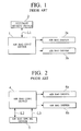
- an occupant sensing device 2 is connected to an air bag control device 1 through a communication line L1, and a driver's seat air bag driver 3a connected to a driver's seat air bag and a passenger seat air bag driver 3b connected to a passenger seat air bag are respectively connected to the air bag control device 1.
- the air bag control device 1 controls, on the basis of the received information, the driver's seat air bag driver 3a connected to the driver's seat air bag and the passenger seat air bag driver 3b connected to the passenger seat air bag.
- an air bag apparatus having the features of the preamble of claim 1, which controls, on the basis of the will of a user of a vehicle, the operation of an air bag apparatus, e.g., the operation of the air bag apparatus such that the driver's seat air bag is developed or not and the passenger seat air bag is developed or not.
- an air bag operation selecting device 5 is connected to an air bag control device 4 through communication lines L2 and L3, and a driver's seat air bag driver 6a connected to a driver's seat air bag and a passenger seat air bag driver 6b connected to a passenger seat air bag are connected to the air bag control device 4.
- the air bag control device 4 communicates with the air bag operation selecting device 5 through the communication line L2 to determine whether the air bag operation selecting device 5 is connected to the air bag control device 4 or not.
- the air bag control device 4 which receives the information further receives drive selecting information, which is transmitted from the air bag operation selecting device 5 through the communication line L3, indicating whether the driver's seat air bag driver 6a is driven or not and the passenger seat air bag driver 6b is driven, etc.
- the air bag control device 4 controls, on the basis of the drive selecting information received as described above, the driver's seat air bag driver 6a connected to the driver's seat air bag and the passenger seat air bag driver 6b connected to the passenger seat air bag.
- the air bag operation selecting device 5 is generally attached to the air bag apparatus of a vehicle in a dealer or the like after the vehicle is out from a mass production line in a vehicle assembly firm. That is, the air bag operation selecting device 5 is attached as a so-called additional device in its after market.
- the air bag apparatus installed on the vehicle in which information is highly frequently exchanged between the air bag apparatus and the peripheral device has been urged to simplify the communication system, especially, reduce communication lines in number at present.
- an object of the present invention to provide an air bag apparatus which can cope with a need to simplify its communication system for an additional peripheral device such as an air bag operation selecting device.
- an air bag apparatus which basically comprises an air bag, an air bag driver for performing drive of the air bag to develop the air bag, and an air bag control device for controlling the drive of the air bag driver.
- the air bag control device has an arrangement in which an air bag operation selecting device having information related to selection of an operation state of the air bag driver can be connected to the air bag control device.
- the air bag control device has a non-volatile storage device, determines a connection state of the air bag operation selecting device to the air bag control device, and stores information related to the determined connection state in the non-volatile storage device.
- the air bag control device controls a drive operation of the air bag driver according to the information related to the connection state stored in the non-volatile storage device and on the basis of the information related to selection of an operation state of the air bag driver.
- An air bag apparatus may further comprise an occupant sensing device for sensing information related to seating of an occupant.
- the air bag control device can preferably control drive of the air bag driver on the basis of the information sensed by the occupant sensing device.
- the occupant sensing device may be a device which can sense information related to the presence/absence of equipment set on a seat, e.g., so-called a child seat, or a setting direction of the equipment.
- the air bag apparatus further comprises a first communication line for connecting the occupant sensing device and the air bag control device to each other and a second communication line for connecting the air bag operation selecting device and the air bag control device to each other.
- the second communication line is satisfactorily connected to the first communication line in parallel. More specifically, a signal corresponding to information related to seating of an occupant and sensed by the occupant sensing device is transmitted to the air bag control device through the first communication line, and a signal corresponding to information related to selection of an operation state of the air bag driver and belonging to the air bag operation selecting device is transmitted to the air bag control device through the second communication line.
- the air bag control device determines a connection state of the air bag operation selecting device to the air bag control device through the second communication line to store information related to the determined connection state in the non-volatile storage device.
- the air bag apparatus may also employ an arrangement in which the air bag control device determines a communication state between the air bag control device and the air bag operation selecting device.
- the air bag control device determines a communication state as a matter of course.
- the air bag control device determines the communication state as an abnormal state because disconnection of the communication line may occur.
- the air bag control device Even if the air bag control device does not respond within the predetermined period of time, when the information related to the connection state stored in the non-volatile storage device corresponds to a state in which the air bag operation selecting device is not connected, the air bag control device need not determine the communication state because the air bag operation selecting device is not connected. For this reason, this case is obviously discriminated from the case wherein the air bag control device does not respond when the air bag operation selecting device is not connected, and determination of the communication state is not performed.
- the air bag apparatus may further comprise a warning unit.
- the air bag control device When a determined communication state between the air bag control device and the air bag operation selecting device is abnormal, the air bag control device preferably operates the warning unit to obtain reliable confirmation.
- the air bag control device when a determined communication state between the air bag control device and the air bag operation selecting device is abnormal, the air bag control device preferably stores information related to the determined communication state in a memory to obtain convenience in repair.
- the air bag control device when the determined communication state between the air bag control device and the air bag operation selecting device is normal, and the information related to the connection state stored in the non-volatile storage device corresponds to a non-connection state, the air bag control device updates the information related to the connection state stored in the non-volatile storage device into a connection state and receives a signal corresponding to the information related to selection of an operation state of the air bag driver and belonging to the air bag operation selecting device to prepare the operation of the air bag.
- the air bag control device when the determined communication state is normal, and the information related to the connection state stored in the non-volatile storage device corresponds to a connection state, the air bag control device receives the signal corresponding to the information related to selection of an operation state of the air bag driver and belonging to the air bag operation selecting device to prepare the operation of the air bag.
- a plurality of air bags are preferably arranged for a driver's seat, a passenger seat, and the like, and air bag drivers are arranged in correspondence with the plurality of air bags.
- the air bag control device preferably performs a series of processes using the information related to the connection state stored in the non-volatile storage device when an ignition switch is in an ON state.
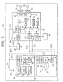
- an air bag apparatus 10 is constituted by an occupant sensing device 20, a driver's seat air bag driver 31, a driver's seat air bag 32, a passenger seat air bag driver 35, a passenger seat air bag 36, an air bag control device 40, an air bag operation selecting device 50, a warning unit 60, and an off-board diagnosis unit 80.
- the occupant sensing device 20 is constituted by a driver's seat position sensor 21 for detecting the position of the driver's seat of a vehicle, a passenger seat position sensor 22 for detecting the position of the passenger seat of the vehicle, a passenger seat weight sensor 23 for detecting a weight acting on the passenger seat, a power source circuit 24 for supplying a necessary electric power to the constituent elements of the occupant sensing device 20, a CPU 25 for controlling the occupant sensing device 20, and a communication circuit 26 for performing communication with the air bag control device 40. Power lines between the power source circuit 24 and each of the sensors 21 to 23 and a power line between the power source circuit 24 and the communication circuit 26 are omitted.
- the driver's seat position sensor 21 detects the position of the driver's seat of the vehicle in the forward and backward directions to transmit the detected information to the CPU 25.
- the CPU 25 which receives the information related to the detected position detects a posture of a driver on the seat on the basis of the detected position.
- the passenger seat position sensor 22 detects the position of the passenger seat of the vehicle in the forward and backward directions to transmit the detected information to the CPU 25.
- the passenger seat weight sensor 23 detects a weight acting on the passenger seat to transmit the detected information to the CPU 25.
- the CPU 25 which receives the information related to the detected position and the detected weight detects a posture of an occupant on the passenger seat, the presence/absence of setting of a so-called child seat, and a setting direction of the child seat.
- the air bag control device 40 is constituted by a G sensor 41 for detecting an acceleration applied on the vehicle to detect collision of the vehicle, an air bag drive control circuit 42 for directly controlling operations of the driver's seat air bag driver 31 and the passenger seat air bag driver 35, a communication circuit 43 for performing communication with the communication circuit 26 of the occupant sensing device 20 and a communication circuit 53 of the air bag operation selecting device 50, a power source circuit 44 for supplying a necessary power to the constituent elements of the air bag control device 40, an EEPROM 45 in which information related to the presence/absence of setting of the air bag operation selecting device 50 is stored, a warning unit control circuit 46 for controlling the warning unit 60, an off-board diagnostic communication circuit 47 for performing communication with the off-board diagnosis unit 80, and a CPU 48 for controlling the air bag control device 40.
- a power line between the communication circuit 44 and the G sensor 41, power lines between the power source circuit 44 and each of the communication circuits 43 and 47, power lines between the power source circuit 44 and each of the control circuits 42 and 46, and a power line between the communication circuit 44 and the EEPROM 45 are omitted. More specifically, the information related to the presence/absence of setting of the air bag operation selecting device 50 and stored in the EEPROM 45 has the form of a flag corresponding to the presence/absence of setting of the air bag operation selecting device 50, and the initial value of the flag F is set to be 0.
- the air bag operation selecting device 50 is constituted by a switch 51 for selecting the operations of the driver's seat air bag driver 31 and the passenger seat air bag driver 35, a power source circuit 52 for supplying a necessary power to the constituent elements of the air bag operation selecting device 50, a communication circuit 53 for performing communication with the communication circuit 43 of the air bag control device 40, and a CPU 54 for controlling the air bag operation selecting device 50.
- a power line between the power source circuit 52 and the communication circuit 53 is omitted.
- the CPU 54 operates only the driver's seat air bag driver 31 on the basis of a switching state of the switch 51, operates only the passenger seat air bag driver 35, operates the driver's seat air bag driver 31 and the passenger seat air bag driver 35, or inhibits the driver's seat air bag driver 31 and the passenger seat air bag driver 35 from operating, so that the CPU 54 can select the operation states of the driver's seat air bag driver 31 and the passenger seat air bag driver 35.
- the driver's seat air bag driver 31 is to develop the driver's seat air bag 32 and includes a squib or the like serving as an igniter.
- the passenger seat air bag driver 35 is to develop the passenger seat air bag 36 and includes a squib.
- the warning unit 60 is an indicator arranged on a meter panel or the like.
- the warning unit 60 is turned on by the warning unit control circuit 46 of the air bag control device 40 when predetermined abnormality occurs in communication between the air bag control device 40 and the air bag operation selecting device 50.
- the off-board diagnosis unit 80 is connected to the air bag control device 40 by a mechanic man or the like of a dealer as needed.
- a record of troubles and a diagnosis result related to the air bag apparatus 10 stored in a memory (not shown) of the air bag control device 40 can be displayed on a screen of the off-board diagnosis unit 80, and various instructions can be input to the air bag control device 40 in response to a predetermined command.
- the record of troubles related to the air bag apparatus 10 represents the history of contents of past troubles, and is stored in a ROM (not shown) in the air bag control device 40.
- the diagnosis result related the air bag apparatus 10 represents the presence/absence of a present trouble or, if the trouble is present, the contents of the trouble, and is temporarily stored in a RAM (not shown) in the air bag control device 40. If there is a trouble of the air bag apparatus 10 in diagnosis, a necessary repair or the like is performed on the basis of the latest diagnosis result with reference to the record of troubles.
- a battery 72 is connected to the power source circuit 24 of the occupant sensing device 20, the communication circuit 44 of the air bag control device 40, the power source circuit 52 of the air bag operation selecting device 50, and the warning unit 60 through an ignition switch 71 and corresponding power supply lines P11 to P14. That is, the occupant sensing device 20, the air bag control device 40, the air bag operation selecting device 50, and the warning unit 60 are operated when the ignition switch 71 is turned on. In other words, processes and controls performed by the CPU 25 of the occupant sensing device 20, the CPU 48 of the air bag control device 40, and the CPU 54 of the air bag operation selecting device 50 are executed when the ignition switch 71 is turned on.
- the communication circuit 43 of the air bag control device 40 and the communication circuit 26 of the occupant sensing device 20 are connected to each other through a communication line L11 serving as a so-called serial communication line, and the communication circuit 26 of the air bag control device 40 and the communication circuit 53 of the air bag operation selecting device 50 are connected to each other through a communication line L12 serving as a serial communication line.
- the communication line L12 is connected to the communication line L11 in parallel.
- Communication between the air bag control device 40 and the occupant sensing device 20 which have the above connection relationship and communication between the air bag control device 40 and the air bag operation selecting device 50 which have the above connection relationship are performed by a so-called polling scheme in which the air bag control device 40 is used as a master station, and the occupant sensing device 20 and the air bag operation selecting device 50 are used as local stations.
- information of a posture of a driver on the driver's seat, a posture of an occupant on a passenger seat, if necessary, the presence/absence of setting of a so-called child seat, a setting direction of the child seat, and the like is transmitted from the occupant sensing device 20 to the air bag control device 40 through the communication line L11.
- Information related to selection of an operation state of the driver's seat air bag driver 31 and the passenger seat air bag driver 35 is intermittently transmitted from the air bag operation selecting device 50 to the air bag control device 40 through the communication line L12 connected to the communication line L11 in parallel at a timing at which communication is not performed between the air bag control device 40 and the occupant sensing device 20.
- the air bag control device 40 since the air bag operation selecting device 50 is a so-called additional device which is not assembled on a production line, it must be determined whether the air bag operation selecting device 50 is connected to the air bag control device 40 in advance. For this reason, the air bag control device 40 has the following arrangement. That is, when the air bag operation selecting device 50 is connected, the air bag control device 40 receives information representing that the air bag operation selecting device 50 is connected, accompanying with reception of the information related to selection of an operation state of the driver's seat air bag driver 31 or the like from the air bag operation selecting device 50 by the air bag control device 40. As a matter of course, when the air bag operation selecting device 50 is not connected, the air bag control device 40 does not any information from the air bag operation selecting device 50.
- the air bag control device 40 can determine the presence/absence of connection of the air bag operation selecting device 50.
- the information related to the presence/absence of connection of the air bag operation selecting device 50 is properly stored in the EEPROM 45 of the air bag control device 40 as a flag F.
- the air bag control device 40 determines that the air bag operation selecting device 50 is connected and that the communication between the air bag control device 40 and the air bag operation selecting device 50 is normally performed, the air bag control device 40 performs the following control.
- the air bag control device 40 determines that collision of the vehicle occurs, and the air bag control device 40 controls, for example, so as to operate only the driver's seat air bag driver 31 and not to operate the passenger seat air bag driver 35, or so as to operate the driver's seat air bag driver 31 by a normal ignition in order to normally develop the driver's seat air bag 32 and so as to operate the passenger seat air bag driver 35 by gradual ignition in order to moderately develop the passenger seat air bag 36 at the beginning, on the basis of information such as the posture of a driver on the driver's seat, the posture of an occupant on the passenger seat, depending on the case, the presence/absence of setting of a so-called child seat, and the setting direction of the child seat, and on the basis of the information related to selection of operation states of the driver's seat air bag driver 31 and the passenger seat air bag driver 35.
- the air bag control device 40 determines that the air bag operation selecting device 50 is connected and that the communication between the air bag control device 40 and the air bag operation selecting device 50 is abnormally performed, since the air bag apparatus must be properly repaired, a user or the like typically recognizes the trouble with the warning unit 60 lighted by the air bag control device 40. In this case, a mechanic or the like of a dealer diagnoses the air bag apparatus 10 by using the off-board diagnosis unit 80. A necessary repair or the like is performed on the basis of the diagnosis result with reference to the record of troubles as needed.
- the air bag control device 40 determines that the air bag operation selecting device 50 is not connected, the air bag control device 40 does not determine whether the communication state between the air bag control device 40 and the air bag operation selecting device 50 is normal or not, and the air bag control device 40 does not make the information related to selection of an operation state of the driver's seat air bag driver 31 or the like input from the air bag operation selecting device 50.
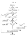
- the air bag apparatus according to this embodiment, the process related to determination of the presence/absence of connection of the air bag operation selecting device 50 performed by the air bag control device 40 and the process related to determination of the presence/absence of abnormal communication between the air bag control device 40 and the air bag operation selecting device 50 will be described below with reference to FIG. 4.
- the CPU 48 in the air bag control device 40 begins operating to start a series of processes.
- step 10 the CPU 48 reads the setting flag F from the EEPROM 45 to store the setting flag F in a register (not shown) in the CPU 48.
- the setting flag F corresponds to discrimination information related to the presence/absence of setting of the air bag operation selecting device 50.
- This setting flag F is stored in the EEPROM 45 in the previous series of processes performed by the CPU 48.
- step 20 (S20) the CPU 48 transmits a communication signal corresponding to the address of the air bag operation selecting device 50 to the communication circuit 53 through the communication circuit 43 to start access to the air bag operation selecting device 50.
- the CPU 54 of the air bag operation selecting device 50 responds to the communication signal received through the communication circuit 53 to transmit information representing that the air bag operation selecting device 50 is connected and information related to selection of an operation state of the driver's seat air bag driver 31 or the like to the communication circuit 43 of the air bag control device 40 through the communication circuit 53, and the CPU 48 of the air bag control device 40 receives each such a information.
- the CPU 48 does not receive any signal.
- step 30 the CPU 48 determines whether the information representing that the air bag operation selecting device 50 is connected and the information related to selection of an operation state of the driver's seat air bag driver 31 or the like are received from the air bag operation selecting device 50 within a predetermined period of time, i.e., whether the air bag operation selecting device 50 responds within the predetermined period of time.
- step 60 the CPU 48 performs a trouble process, i.e., lights the warning unit 60 through the warning unit control circuit 46.
- a trouble process i.e., lights the warning unit 60 through the warning unit control circuit 46.
- information representing that the disconnection occurs is stored in a RAM 49 in the air bag control device 40. This information is a kind of diagnosis result for the air bag apparatus 10, and is used in a repair. And the series of processes are completed.
- step 70 determines in step 70 (S70) whether the response is normal or not. More specifically, this determination is performed by checking the presence/absence of abnormal communication represented by so-called overrunning or a so-called framing error with respect to the information representing that the air bag operation selecting device 50 is connected and the information related to selection of an operation state of the driver's seat air bag driver 31 or the like, which are transmitted from the air bag operation selecting device 50.
- step 70 S70
- step 60 the CPU 48 performs a trouble process, i.e., lights the warning unit 60 through the warning unit control circuit 46.
- information representing that the abnormal communication occurs is stored in the RAM 49 in the air bag control device 40. This information is also a kind of diagnosis result for the air bag apparatus 10 and is used for a repair or the like. And the series of processes are completed.
- step 70 If the CPU 48 determines in step 70 that the air bag operation selecting device 50 normally responds, the CPU 48 determines in step 80 (S80) that communication between the air bag operation selecting device 50 and the air bag control device 40 is normal.
- step 120 S120
- the CPU 48 actually performs an input process with respect to the information related to selection of an operation state of the driver's seat air bag driver 31 or the like and output from the air bag operation selecting device 50. And the series of processes are completed.
- a setting flag serving as discrimination information representing whether the air bag operation selecting device 50 is set is stored in the EEPROM 45 serving as a non-volatile memory, and it is determined on the basis of the setting flag whether the air bag operation selecting device 50 is set while the ignition switch 71 is set in an ON state. For this reason, a single-purpose line for determining the setting as in the prior art can be excluded, and the communication system can be effectively simplified.
- the setting flag in the EEPROM 45 corresponds to the state in which the air bag operation selecting device 50 is not set and when the air bag operation selecting device 50 does not respond, the process is completed without determining disconnection, overrunning, or the like and performing a trouble process. For this reason, even in an arrangement in which a communication system is simplified, disconnection or the like can be correctly determined under a situation in which the air bag operation selecting device 50 is set.
- the warning unit is lit, and the determination result is held in the memory. For this reason, a user or the like can correctly understand the situation and is highly convenient for repair.
- the determination process regarding setting of the air bag operation selecting device 50 and the reading process regarding the information from the air bag operation selecting device 50 are performed as a series of processes each time the ignition switch 71 is turned on, and therefore, the processes themselves are effectively simplified.
- the EEPROM As a non-volatile memory for storing a setting flag serving as discrimination information representing whether the air bag operation selecting device 50 is set or not, the EEPROM is used.
- a flash memory may be used as a EEPROM, and another semiconductor element such as EPROM or NV RAM may also be used, and a recording medium such as a magnetic disk, an optical disk, or an optical-magnetic disk may also be used as needed.
- RAMs (not shown) in the air bag control device 40
- these RAMs may be individually provided or may be integrally arranged as one unit as needed.
- the RAMs and the RAM 49 may be commonly used as needed.
- the CPU 48 reads the setting flag F from the EEPROM 45 to store the setting flag F in the register (not shown) in the CPU 48
- the setting flag F may be stored in a RAM (not shown) in the CPU 48.
- a driver's seat air bag and a passenger seat air bag have been explained as object to be controlled.
- a so-called side air bag or the like can be used as an object to be controlled.
Landscapes
- Engineering & Computer Science (AREA)
- Mechanical Engineering (AREA)
- Air Bags (AREA)
- Air-Conditioning For Vehicles (AREA)
Claims (15)
- Dispositif de coussin d'air, comprenant:caractérisé en ce que ledit dispositif de commande du coussin d'air (40) comporte un dispositif de mémoire non volatile (45) déterminant un état de connexion dudit dispositif de sélection du mode opératoire du coussin d'air (50) sur ledit dispositif de commande du coussin d'air (40) et enregistrant des informations concernant un état de connexion ainsi déterminé dans ledit dispositif de mémoire non volatile (45).un coussin d'air (32);un dispositif d'entraínement du coussin d'air (31), destiné à entraíner ledit coussin d'air (32), de sorte à déployer ledit coussin d'air; etun dispositif de commande du coussin d'air (40), assurant la commande dudit entraínement dudit dispositif d'entraínement du coussin d'air (31), un dispositif de sélection du mode opératoire du coussin d'air (50) pouvant être connecté audit dispositif de commande du coussin d'air (40), ledit dispositif de sélection du mode opératoire du coussin d'air (50) contenant des informations concernant la sélection d'un mode opératoire dudit dispositif d'entraínement du coussin d'air (31);
- Dispositif de coussin d'air selon la revendication 1, dans lequel ledit dispositif de commande du coussin d'air (40) assure la commande dudit entraínement dudit dispositif d'entraínement du coussin d'air (31) en fonction desdites informations concernant ledit état de connexion enregistré dans ledit dispositif de mémoire non volatile (45) et sur la base desdites informations concernant ladite sélection dudit mode opératoire dudit dispositif d'entraínement du coussin d'air (31).
- Dispositif de coussin d'air selon la revendication 1, comprenant en outre un dispositif de détection d'un occupant (20), détectant des informations concernant la position assise d'un occupant,
ledit dispositif de commande du coussin d'air (40) assurant en outre la commande dudit entraínement dudit dispositif d'entraínement du coussin d'air (31) sur la base desdites informations détectées par ledit dispositif de détection de l'occupant (20). - Dispositif de coussin d'air selon la revendication 3, dans lequel ledit dispositif de détection de l'occupant (20) détecte en outre des informations concernant un objet placé sur un siège.
- Dispositif de coussin d'air selon la revendication 3, comprenant en outre:une première ligne de communication (L11) connectant ledit dispositif de détection de l'occupant (20) audit dispositif de commande du coussin d'air (40), un signal correspondant aux dites informations concernant ladite position assise dudit occupant détectées par ledit dispositif de détection de l'occupant (20) étant transmis vers ledit dispositif de commande du coussin d'air (40) à travers ladite première ligne de communication; etune deuxième ligne de communication (L12) connectant ledit dispositif de sélection du mode opératoire du coussin d'air (50) audit dispositif de commande du coussin d'air (40), un signal correspondant aux informations concernant ladite sélection dudit mode opératoire dudit dispositif d'entraínement du coussin d'air (31) et provenant dudit dispositif de sélection du mode opératoire du coussin d'air (50) étant transmis vers ledit dispositif de commande du coussin d'air (40) à travers ladite deuxième ligne de communication (L12), ladite deuxième ligne de communication (L12) étant connectée en parallèle à ladite première ligne de communication (L11);ledit dispositif de commande du coussin d'air (40) déterminant ledit état de connexion dudit dispositif de sélection du mode opératoire (50) sur ledit dispositif de commande du coussin d'air (40) à travers ladite deuxième ligne de communication (L12) et enregistrant lesdites informations concernant ledit état de connexion ainsi déterminé dans ledit dispositif de mémoire non volatile (45).
- Dispositif de coussin d'air selon la revendication 1, dans lequel ledit dispositif de commande du coussin d'air (40) détermine en outre un état de communication entre ledit dispositif de commande du coussin d'air (40) et ledit dispositif de sélection du mode opératoire du coussin d'air (50).
- Dispositif de coussin d'air selon la revendication 6, dans lequel ledit dispositif de commande du coussin d'air (40) détermine ledit état de communication lorsque ledit dispositif de commande du coussin d'air (40) réagit dans le cadre d'une période de temps prédéterminée.
- Dispositif de coussin d'air selon la revendication 6, dans lequel, ledit dispositif de commande du coussin d'air (40) ne réagissant pas dans le cadre d'une période de temps prédéterminée, lesdites informations concernant ledit état de connexion enregistrées dans ledit dispositif de mémoire non volatile (45) correspondant à un état dans lequel ledit dispositif de sélection du mode opératoire du coussin d'air (50) est connecté, ledit dispositif de commande du coussin d'air (40) détermine que ledit état de communication correspond à un état anormal.
- Dispositif de coussin d'air selon la revendication 6, dans lequel, ledit dispositif de commande du coussin d'air (40) ne réagissant pas dans le cadre d'une période de temps prédéterminée, lesdites informations concernant ledit état de connexion enregistrées dans ledit dispositif de mémoire non volatile (45) correspondant à un état dans lequel ledit dispositif de sélection du mode opératoire du coussin d'air (50) n'est pas connecté, ledit dispositif de commande du coussin d'air (40) ne détermine pas ledit état de communication.
- Dispositif de coussin d'air selon la revendication 6, comprenant en outre une unité d'avertissement (60);
ledit dispositif de commande du coussin d'air (40) actionnant ladite unité d'avertissement (60) lorsqu'il détermine que ladite communication est anormale. - Dispositif de coussin d'air selon la revendication 6, dans lequel ledit dispositif de commande du coussin d'air (40) enregistre les informations concernant ledit état de communication qu'il a déterminé dans un dispositif de mémoire lorsque ledit état de communication déterminé est anormal.
- Dispositif de coussin d'air selon la revendication 6, dans lequel ledit dispositif de commande du coussin d'air (40) assure la mise à jour desdites informations concernant ledit état de connexion enregistrées dans ledit dispositif de mémoire non volatile (45) en un état de connexion et reçoit un signal correspondant aux dites informations concernant ladite sélection dudit mode opératoire dudit dispositif d'entraínement du coussin d'air (31) et provenant dudit dispositif de sélection du mode opératoire du coussin d'air (50) lorsque ledit état de communication déterminé est normal, lesdites informations concernant ledit état de connexion enregistrées dans ledit dispositif de mémoire non volatile (45) correspondant à un état de non-connexion.
- Dispositif de coussin d'air selon la revendication 6, dans lequel ledit dispositif de commande du coussin d'air (40) reçoit ledit signal correspondant aux dites informations concernant ladite sélection dudit mode opératoire dudit dispositif d'entraínement du coussin d'air (31) et provenant dudit dispositif de sélection du mode opératoire du coussin d'air (50) lorsque ledit état de communication déterminé est normal, lesdites informations concernant ledit état de connexion enregistrées dans ledit dispositif de mémoire non volatile (45) correspondant à un état de connexion.
- Dispositif de coussin d'air selon la revendication 1, comportant plusieurs desdits coussins d'air (32, 36), plusieurs desdits dispositifs d'entraínement du coussin d'air (31, 35) étant agencés de manière correspondante.
- Dispositif de coussin d'air selon la revendication 1, dans lequel ledit dispositif de commande du coussin d'air (40) utilise lesdites informations concernant ledit état de connexion enregistrées dans ledit dispositif de mémoire non volatile (45) lors du branchement d'un interrupteur d'allumage.
Applications Claiming Priority (2)
| Application Number | Priority Date | Filing Date | Title |
|---|---|---|---|
| JP00103198A JP3572921B2 (ja) | 1998-01-06 | 1998-01-06 | エアバック装置 |
| JP103198 | 1998-01-06 |
Publications (3)
| Publication Number | Publication Date |
|---|---|
| EP0928721A2 EP0928721A2 (fr) | 1999-07-14 |
| EP0928721A3 EP0928721A3 (fr) | 1999-12-29 |
| EP0928721B1 true EP0928721B1 (fr) | 2004-03-17 |
Family
ID=11490208
Family Applications (1)
| Application Number | Title | Priority Date | Filing Date |
|---|---|---|---|
| EP99300065A Expired - Lifetime EP0928721B1 (fr) | 1998-01-06 | 1999-01-06 | Système airbag avec dispositif de sélection du mode operatoire du système airbag |
Country Status (4)
| Country | Link |
|---|---|
| US (1) | US6253132B1 (fr) |
| EP (1) | EP0928721B1 (fr) |
| JP (1) | JP3572921B2 (fr) |
| DE (1) | DE69915521T2 (fr) |
Families Citing this family (3)
| Publication number | Priority date | Publication date | Assignee | Title |
|---|---|---|---|---|
| DE10321935A1 (de) * | 2003-05-15 | 2004-12-02 | Trw Occupant Restraint Systems Gmbh & Co. Kg | Datenspeichersystem für ein Fahrzeuginsassenrückhaltesystem |
| DE10333204A1 (de) * | 2003-07-22 | 2005-02-24 | Conti Temic Microelectronic Gmbh | Verfahren und Vorrichtung zur Druckmessung |
| JP2005263039A (ja) * | 2004-03-18 | 2005-09-29 | Denso Corp | 乗員保護システム |
Family Cites Families (16)
| Publication number | Priority date | Publication date | Assignee | Title |
|---|---|---|---|---|
| US4059822A (en) * | 1972-04-10 | 1977-11-22 | Toyota Jidosha Kogyo Kabushiki Kaisha | Fault detecting system for vehicle occupants protective apparatus |
| DE2851333A1 (de) * | 1978-11-28 | 1980-06-12 | Bosch Gmbh Robert | Pruefschaltung fuer die ausloesevorrichtung einer den schutz der insassen eines fahrzeugs waehrend eines unfalles dienenden sicherheitseinrichtung |
| JPH05459Y2 (fr) * | 1988-05-11 | 1993-01-07 | ||
| US5422965A (en) * | 1992-02-18 | 1995-06-06 | Hitachi, Ltd. | Air bag operation device |
| US5605348A (en) | 1993-11-03 | 1997-02-25 | Trw Vehicle Safety Systems Inc. | Method and apparatus for sensing a rearward facing child seat |
| DE4424020A1 (de) * | 1994-07-08 | 1996-01-11 | Telefunken Microelectron | Prüfverfahren für eine passive Sicherheitseinrichtung in Kraftfahrzeugen |
| FR2732286B1 (fr) * | 1995-03-31 | 1997-06-13 | Davey Bickford | Dispositif de securite d'un vehicule |
| GB9604825D0 (en) | 1996-03-07 | 1996-05-08 | Amp Gmbh | Seat occupancy sensor device |
| DE19609076C1 (de) * | 1996-03-08 | 1997-08-14 | Siemens Ag | Verfahren zum Auslösen eines Rückhaltemittels in einem Fahrzeug |
| JPH101031A (ja) | 1996-06-17 | 1998-01-06 | Okamoto Ind Inc | ワイパーブレードクリーナー |
| JPH1032883A (ja) * | 1996-07-16 | 1998-02-03 | Alps Electric Co Ltd | 車両用多重通信装置 |
| DE19643013C1 (de) * | 1996-10-18 | 1998-02-12 | Telefunken Microelectron | Datenübertragungssystem |
| US6088639A (en) * | 1997-10-03 | 2000-07-11 | Delco Electronics Corporation | Method of enabling and disabling occupant restraints |
| US5964815A (en) * | 1997-10-21 | 1999-10-12 | Trw Inc. | Occupant restraint system having serially connected devices, a method for providing the restraint system and a method for using the restraint system |
| US5992880A (en) * | 1997-12-18 | 1999-11-30 | Ford Global Technologies, Inc. | Vehicle airbag deactivation switch circuit |
| US6045156A (en) * | 1998-07-21 | 2000-04-04 | Delco Electronics Corp. | Supplement restraint system having deployment inhibit apparatus |
-
1998
- 1998-01-06 JP JP00103198A patent/JP3572921B2/ja not_active Expired - Fee Related
-
1999
- 1999-01-04 US US09/224,996 patent/US6253132B1/en not_active Expired - Fee Related
- 1999-01-06 EP EP99300065A patent/EP0928721B1/fr not_active Expired - Lifetime
- 1999-01-06 DE DE69915521T patent/DE69915521T2/de not_active Expired - Fee Related
Also Published As
| Publication number | Publication date |
|---|---|
| JPH11192919A (ja) | 1999-07-21 |
| US6253132B1 (en) | 2001-06-26 |
| JP3572921B2 (ja) | 2004-10-06 |
| DE69915521T2 (de) | 2005-02-03 |
| EP0928721A3 (fr) | 1999-12-29 |
| DE69915521D1 (de) | 2004-04-22 |
| EP0928721A2 (fr) | 1999-07-14 |
Similar Documents
| Publication | Publication Date | Title |
|---|---|---|
| US5467277A (en) | Apparatus and method for automobile control using a control characteristic which can be adjusted by the driver | |
| US6225898B1 (en) | Vehicle diagnosis system having transponder for OBD III | |
| US6501368B1 (en) | Electrical control apparatus including a plurality of programmable modules | |
| US4926331A (en) | Truck operation monitoring system | |
| JP2002229542A (ja) | 車載用映像切換装置 | |
| US5796332A (en) | Diagnostic system for sensing and displaying functions of a motor vehicle heating apparatus | |
| EP0928721B1 (fr) | Système airbag avec dispositif de sélection du mode operatoire du système airbag | |
| US6293583B1 (en) | Apparatus for activating passive safety device | |
| JP3714111B2 (ja) | 車両用乗員保護システム | |
| EP0936111A1 (fr) | Unité de contrÔle pour airbag avec dispositif d' empêchement de la réutilisation de l' unité de contrÔle | |
| JP2009126323A (ja) | 車両用故障診断装置 | |
| JP4914692B2 (ja) | 自動車用制御装置 | |
| JP3719371B2 (ja) | 車両用乗員保護システム | |
| JP2004020461A (ja) | 車両用故障診断装置 | |
| US6273460B1 (en) | Smart remote indicator module | |
| US6122574A (en) | Method for detecting abnormality of control unit and control unit employing same | |
| US6828904B2 (en) | Impact sensor post collision notification system | |
| JP2924620B2 (ja) | 車両用故障診断装置 | |
| KR200279114Y1 (ko) | 이동통신 단말기를 이용하여 자동차 자기진단 정보를출력하는 자동차 자기진단 장치 | |
| US11847830B2 (en) | Vehicle and method of controlling the same | |
| JP3475734B2 (ja) | 制御基盤 | |
| JP3785318B2 (ja) | 車両運行情報収集装置及び車両運行情報収集装置の自己診断方法 | |
| JP2002106408A (ja) | 車両用電子制御装置 | |
| JPH03217356A (ja) | エアバッグ制御装置 | |
| JP2002116822A (ja) | システム照合装置 |
Legal Events
| Date | Code | Title | Description |
|---|---|---|---|
| PUAI | Public reference made under article 153(3) epc to a published international application that has entered the european phase |
Free format text: ORIGINAL CODE: 0009012 |
|
| 17P | Request for examination filed |
Effective date: 19990205 |
|
| AK | Designated contracting states |
Kind code of ref document: A2 Designated state(s): DE GB |
|
| AX | Request for extension of the european patent |
Free format text: AL;LT;LV;MK;RO;SI |
|
| PUAL | Search report despatched |
Free format text: ORIGINAL CODE: 0009013 |
|
| AK | Designated contracting states |
Kind code of ref document: A3 Designated state(s): AT BE CH CY DE DK ES FI FR GB GR IE IT LI LU MC NL PT SE |
|
| AX | Request for extension of the european patent |
Free format text: AL;LT;LV;MK;RO;SI |
|
| AKX | Designation fees paid |
Free format text: DE GB |
|
| 17Q | First examination report despatched |
Effective date: 20021122 |
|
| GRAP | Despatch of communication of intention to grant a patent |
Free format text: ORIGINAL CODE: EPIDOSNIGR1 |
|
| GRAS | Grant fee paid |
Free format text: ORIGINAL CODE: EPIDOSNIGR3 |
|
| GRAA | (expected) grant |
Free format text: ORIGINAL CODE: 0009210 |
|
| AK | Designated contracting states |
Kind code of ref document: B1 Designated state(s): DE GB |
|
| REG | Reference to a national code |
Ref country code: GB Ref legal event code: FG4D |
|
| REF | Corresponds to: |
Ref document number: 69915521 Country of ref document: DE Date of ref document: 20040422 Kind code of ref document: P |
|
| PLBE | No opposition filed within time limit |
Free format text: ORIGINAL CODE: 0009261 |
|
| STAA | Information on the status of an ep patent application or granted ep patent |
Free format text: STATUS: NO OPPOSITION FILED WITHIN TIME LIMIT |
|
| 26N | No opposition filed |
Effective date: 20041220 |
|
| PGFP | Annual fee paid to national office [announced via postgrant information from national office to epo] |
Ref country code: GB Payment date: 20070103 Year of fee payment: 9 |
|
| PGFP | Annual fee paid to national office [announced via postgrant information from national office to epo] |
Ref country code: DE Payment date: 20070104 Year of fee payment: 9 |
|
| GBPC | Gb: european patent ceased through non-payment of renewal fee |
Effective date: 20080106 |
|
| PG25 | Lapsed in a contracting state [announced via postgrant information from national office to epo] |
Ref country code: DE Free format text: LAPSE BECAUSE OF NON-PAYMENT OF DUE FEES Effective date: 20080801 |
|
| PG25 | Lapsed in a contracting state [announced via postgrant information from national office to epo] |
Ref country code: GB Free format text: LAPSE BECAUSE OF NON-PAYMENT OF DUE FEES Effective date: 20080106 |