EP0926856A2 - Unterdrückung von Übersprechen in einem Funknetzwerk - Google Patents
Unterdrückung von Übersprechen in einem Funknetzwerk Download PDFInfo
- Publication number
- EP0926856A2 EP0926856A2 EP98310598A EP98310598A EP0926856A2 EP 0926856 A2 EP0926856 A2 EP 0926856A2 EP 98310598 A EP98310598 A EP 98310598A EP 98310598 A EP98310598 A EP 98310598A EP 0926856 A2 EP0926856 A2 EP 0926856A2
- Authority
- EP
- European Patent Office
- Prior art keywords
- data
- identification
- number data
- transmission
- reception
- Prior art date
- Legal status (The legal status is an assumption and is not a legal conclusion. Google has not performed a legal analysis and makes no representation as to the accuracy of the status listed.)
- Withdrawn
Links
Images
Classifications
-
- H—ELECTRICITY
- H04—ELECTRIC COMMUNICATION TECHNIQUE
- H04L—TRANSMISSION OF DIGITAL INFORMATION, e.g. TELEGRAPHIC COMMUNICATION
- H04L1/00—Arrangements for detecting or preventing errors in the information received
- H04L1/004—Arrangements for detecting or preventing errors in the information received by using forward error control
- H04L1/0041—Arrangements at the transmitter end
-
- H—ELECTRICITY
- H04—ELECTRIC COMMUNICATION TECHNIQUE
- H04L—TRANSMISSION OF DIGITAL INFORMATION, e.g. TELEGRAPHIC COMMUNICATION
- H04L1/00—Arrangements for detecting or preventing errors in the information received
- H04L1/004—Arrangements for detecting or preventing errors in the information received by using forward error control
- H04L1/0056—Systems characterized by the type of code used
- H04L1/0061—Error detection codes
-
- H—ELECTRICITY
- H04—ELECTRIC COMMUNICATION TECHNIQUE
- H04L—TRANSMISSION OF DIGITAL INFORMATION, e.g. TELEGRAPHIC COMMUNICATION
- H04L27/00—Modulated-carrier systems
- H04L27/26—Systems using multi-frequency codes
- H04L27/2601—Multicarrier modulation systems
Definitions
- This invention relates to a transmitter, a receiver, and a communication system and a communication method, and more particularly, is applicable to a radio network system for radio-transmitting digital data.
- the radio network system includes a system for radio-transmitting digital data such as image data between an AV (Audio Video) unit sets and a PC (Personal Computer) in a house or company.
- the radio network system realizes multi carrier transmission by using an orthogonal-frequency-division multiplexing system referred to as the orthogonal frequency division multiplex (OFDM) system as a modulation system.
- OFDM orthogonal frequency division multiplex
- an object of this invention is to provide a transmitter, a receiver, and a communication system and communication method capable of avoiding crosstalk with a simple structure.
- the foregoing object and other objects of the invention have been achieved by the provision of a transmitter for transmitting input data after applying predetermined data processing to the input data.
- the transmitter comprises: error-detection-code addition means for adding an error detection code to the input data; logical operation means for generating transmission data by applying the logical operation between the output data output from the error-detection-code addition means and the identification-number data assigned to the transmitter to the transmission data; and transmission means for transmitting the transmission data after applying predetermined transmission processing to the transmission data.
- this invention provides a receiver for receiving a transmission signal transmitted from a transmitter.
- the receiver comprises: reception means for receiving the transmission signal; logical operation means for performing the logical operation between the reception data received by the reception means and the identification-number data assigned to the receiver; and error detection means for detecting an error in the output data in accordance with an error detection code added to the output data output from the logical operation means and disusing the output data when the error is detected.
- this invention provides a communication system for performing communication between a transmitter and a receiver.
- the transmitter has error-detection-code addition means for adding an error detection code to input data, first logical operation means for generating transmission data by performing the logical operation between the first output data output from the error-detection-code addition means and the first identification-number data assigned to the transmitter, and transmission means for transmitting a transmission signal generated by applying predetermined transmission processing to the transmission data.
- the receiver has reception means for receiving the transmission signal, second logical operation means for performing the logical operation between reception data received by the reception means and the second identification-number data assigned to the receiver and same as the first identification-number data, and error detection means for detecting an error in the second output data in accordance with the error detection code added to the second output data output from the second logical operation means and disusing the second output data when the error is detected.
- this invention provides a communication method, which comprises the steps of: generating the first output data by adding an error detection code to input data; generating transmission data by performing the logical operation between the first output data and the first identification-number data; generating and transmitting a transmission signal by applying predetermined transmission processing to the transmission data; generating the second output data by performing the logical operation between reception data obtained by receiving the transmission signal and the second identification-number data same as the first identification-number data; and detecting an error in the second output data in accordance with an error detection code added to the second output data and disusing the second output data when the error is detected.
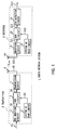
- symbol 1 denotes a radio network system to which the present invention is applied, which has a transmitter 2 and a receiver 3.
- the transmitter 2 and the receiver 3 are mounted on an AV unit or PC set in a house or company and used for the communication between AV units, the communication from an AV unit to a PC, or the communication from a PC to an AV unit.
- the transmitter 2 inputs transmission data S1 supplied through a predetermined data processing circuit to a cyclic redundancy check (CRC) addition circuit 4.
- the CRC addition circuit 4 adds a CRC code to the transmission data S1 every predetermined number of bits and outputs transmission data S2 thereby obtained to an exclusive-OR (XOR) circuit 5.
- XOR exclusive-OR
- a system ID number peculiar to the radio network system 1 to which the transmitter 2 belongs is previously set to the transmitter 2 and stored in, for example, storage means such as an integrated circuit (IC) card.
- a system ID read circuit 6 reads a system ID number from the storage means and outputs the system ID number to the exclusive-OR circuit 5 as system ID number data S3.
- the exclusive-OR circuit 5 computes the exclusive OR between the transmission data S2 and the system ID number data S3 every predetermined number of bits as described above and outputs transmission data S4 thereby obtained to a transmission circuit 7.
- the transmission circuit 7 performs the multicarrier modulation processing according to the OFDM method to generate transmission signal S5, and supplies the signal S5 to an antenna 8. Thereby, the transmission signal S5 is transmitted through the antenna 8.
- the receiver 3 inputs reception signal S10 received by the antenna 10 to a reception circuit 11.
- the reception circuit 11 performs a predetermined demodulation processing according to the OFDM method to generate reception data S11, and outputs the data S11 to an exclusive-OR circuit 12.
- a system ID number is previously set to the receiver 3 similarly to the case of the transmitter 2 and stored in storage means.
- a system ID read circuit 13 reads the system ID number and outputs the ID number to the exclusive-OR circuit 12 as system ID number data S12.
- the exclusive-OR circuit 12 computes the exclusive OR between the reception data S11 and the system ID number data S12 every predetermined number of bits and outputs the reception data S13 thereby obtained to a CRC detection circuit 14.
- the CRC detection circuit 14 detects an error in the reception data S13 by using a CRC code and outputs reception data S14 thereby obtained to a predetermined data processing circuit provided at the rear stage.
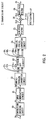
- the structure of the transmission circuit 7 is described below by referring to Fig. 2.
- the transmission circuit 7 inputs the transmission data S4 output from the exclusive-OR circuit 5 to a convolution-encoding circuit 20.
- the convolution-encoding circuit 20 convolution-encodes the transmission data S4 and outputs the transmission data S5 thereby obtained to a Quadrature phase shift keying (QPSK modulation) circuit 21.
- QPSK modulation Quadrature phase shift keying
- the QPSK modulation circuit 21 QPSK-modulates the transmission data S5 and outputs transmission signal S6 thereby obtained to a serial-parallel conversion circuit 22.
- the serial-parallel conversion circuit 22 converts the transmission signal S6 supplied in the form of a serial data string into transmission signals S7 1 to S7 N of a parallel data string and outputs the signals S7 1 to S7 N to an inverse fast Fourier transform (inverse FFT) circuit 23.
- the inverse fast Fourier transform circuit 23 applies the inverse fast Fourier transform to the transmission signals S7 1 to S7 N to map the transmission signals S7 1 to S7 N to frequency-region data, and outputs transmission signals S8 1 to S8 N thereby obtained to a parallel-serial conversion circuit 24.
- the parallel-serial conversion circuit 24 converts the transmission signals S8 1 to S8 N supplied in the form of a parallel data string into a serial data string and outputs transmission signal S9 thereby obtained to a low-pass filter 25.
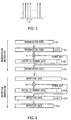
- Fig. 3 shows a spectrum of a carrier waveform of the OFDM method.
- the transmission signal S6 is assigned to subcarriers perpendicularly intersecting each other at a frequency interval of f 0 to transmit the transmission signal S6.
- the OFDM method parallel-converts the transmission signal S6, applies the inverse fast Fourier transform to the parallel-converted transmission signals S7 1 to S7 N , and thereby assigns the transmission signals S7 1 to S7 N to subcarriers.
- the method fetches the data assigned to the subcarriers by capturing signal components from the subcarriers every interval f 0 and performing the fast Fourier transform processing.
- the low-pass filter 25 removes unnecessary components and noises out of low frequencies from the transmission signal S9 and outputs the transmission signal S10 thereby obtained to a frequency conversion circuit 26.
- the frequency conversion circuit 26 multiplies the transmission signal S10 by a local oscillation signal S11 supplied from an oscillator 27 to generate transmission signal S12 frequency-converted into a predetermined frequency, and outputs the signal S12 to a band-pass filter 28.
- the band-pass filter 28 removes unnecessary components and noises out of the band from the transmission signal S12 and supplies the transmission signal S5 thereby obtained to the antenna 7.
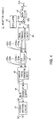
- the reception circuit 11 inputs the reception signal S10 received through the antenna 10 to a band-pass filter 40.
- the band-pass filter 40 removes unnecessary components and noises out of the band from the reception signal S10 and outputs reception signal S20 thereby obtained to a frequency conversion circuit 41.
- the frequency conversion circuit 41 multiplies the reception signal S20 by the local oscillation signal S21 supplied from an oscillator 42 to generate intermediate-frequency reception signal S22, and outputs the signal S22 to a serial-parallel conversion circuit 43.
- the serial-parallel conversion circuit 43 parallel-converts the reception signal S22 and outputs reception signals S23 1 to S23 N thereby obtained to a fast Fourier transform (FFT) circuit 44.
- the fast Fourier transform circuit 44 applies the fast Fourier transform processing to the reception signals S23 1 to S23 N and outputs reception signals S24 1 to S24 N thereby obtained to a parallel-serial conversion circuit 45.
- the serial-parallel conversion circuit 45 converts the reception signals S24 1 to S24 N into reception signal S25 of a serial data string and outputs the signal S25 to a QPSK demodulation circuit 46.
- the serial-parallel conversion circuit 43, the fast Fourier transform circuit 44, and the parallel-serial conversion circuit 45 decode the reception signal S22 according to the OFDM method. That is, effective data is cut off by the serial-parallel conversion circuit 43 and a reception waveform is captured every interval f 0 and converted into parallel data.
- the output of the serial-parallel conversion circuit 43 is supplied to the fast Fourier transform circuit 44 and fast-Fourier-transformed.
- decoding according to the OFDM method is performed by fast-Fourier-transforming a waveform sampled every interval f 0 .
- the QPSK demodulation circuit 46 applies the QPSK demodulation processing to the reception signal S25 to restore the reception data S26, and outputs the reception data S26 to a Viterbi-decoding circuit 47.
- the Viterbi-decoding circuit 47 Viterbi-decodes the reception data S26 and outputs the reception data S11 thereby obtained to the exclusive-OR circuit 12.
- the CRC addition circuit 4 adds a CRC code to the reception data S1 every predetermined number of bits to generate the transmission data S2, and outputs the data S2 to the exclusive-OR circuit 5.
- the system ID read circuit 6 applies the data processing for equalizing the length of the system ID number data S3 with that of the transmission data S2 to the data S3 and then, outputs the system ID number data S3 to the exclusive-OR circuit 5.
- the system ID read circuit 6 When the length of the system ID number data S3 is smaller than that of the transmission data S2, for example, when the length of the system ID number data S3 is sixty-four bits and that of the transmission data S2 is sixty-seven bits, the system ID read circuit 6 generates the system ID number data S3 by combining three fixed bits "000" with the tail of the system ID number data S3 and equalizes the length of the system ID number data S3 with that of the transmission data S2, and thereafter outputs the system ID number data S3 to the exclusive-OR circuit 5.
- the exclusive-OR circuit 5 generates the transmission data S4 by computing the exclusive OR between the transmission data S2 and the system ID number data S3 every predetermined number of bits.
- the transmission circuit 7 applies a predetermined modulation processing to the transmission data S4 and then, the data S4 is transmitted through the antenna 8.
- the receiver 3 supplies the reception signal S10 received through the antenna 10 to the reception circuit 11 and applies a predetermined demodulation processing to the signal S10 through the reception circuit 11 and thereafter, outputs the signal S10 to the exclusive-OR circuit 12.
- the system ID read circuit 13 generates the system ID data S12 by inserting a fixed bit into the system ID number data S12 similarly to the case of the system ID read circuit 6 of the transmitter 2, equalizes the length of the system ID number data S12 with that of the reception data S11, and then outputs the system ID number data S12 to the exclusive-OR circuit 12.
- the exclusive-OR circuit 12 computes the exclusive OR between the reception data S11 and the system ID number data S12 every predetermined number of bits and outputs the reception data S13 thereby obtained to the CRC detection circuit 14.
- the CRC detection circuit 14 detects an error in the reception data S13 by using a CRC code and outputs the reception data S14 thereby obtained to a predetermined data processing circuit.
- step SP2 after entered from step SP1, the CRC addition circuit 4 adds a CRC code to the transmission data S1.
- the exclusive-OR circuit 5 computes the exclusive OR between the transmission data S2 to which a CRC code is added and the system ID number data S3 supplied from the system ID read circuit 6 and outputs the transmission data S4 thereby obtained to the transmission circuit 7.
- the transmission circuit 7 applies the multicarrier modulation processing to the transmission data S4 to generate the transmission signal S5, and transmits the signal S5 through the antenna 8. Then, the processing proceeds to step SP5 to be terminated.
- step SP11 after entered from step SP10, the reception circuit 11 applies the multicarrier demodulation processing to the reception signal S10 received through the antenna 10 to generate the reception data S11, and outputs the signal S10 to the exclusive-OR circuit 12.
- the exclusive-OR circuit 12 computes the exclusive OR between the reception data S11 and the system ID number data S3 supplied from the system ID read circuit 13 and outputs the reception data S13 thereby obtained to the CRC detection circuit 14.
- the CRC detection circuit 14 detects an error in the reception data S13 and outputs the reception data S14 thereby obtained to a data processing circuit at the rear stage. Then, the processing proceeds to step SP14 to be terminated.
- the exclusive-OR circuit 5 computes the exclusive OR between the transmission data S2 to which a CRC code is added and the system ID number data S3 peculiar to the radio network system 1 and transmits the transmission data S4 thereby obtained.
- the exclusive-OR circuit 12 computes the exclusive OR between the reception data S11 and the system ID number data S12 and outputs the reception data S13 thereby obtained to the CRC detection circuit 14.
- the CRC detection circuit 14 checks the reception data S13 for errors by using a CRC code and outputs the reception data S14 thereby obtained to a data processing circuit at the rear stage.
- the exclusive-OR circuit 12 computes an exclusive OR because the system ID number data S3 and S12 of the transmitter 2 and receiver 3 are the same. Thereby, an exclusive OR is computed for the transmission data S2 up to twice. Therefore, the exclusive-OR circuit 12 restores the reception data S13 same as the transmission data S2 of the transmitter 2 and outputs the data S13 to the CRC detection circuit 14.
- the CRC detection circuit 14 generates the reception data S14 by checking the reception data S13 for errors by using a CRC code and outputs the reception data S14.
- the receiver 3 when receiving a transmission signal from a transmitter belonging to other radio network system, the receiver 3 cannot restore original transmission data even if an exclusive OR is computed by the exclusive-OR circuit 12 because the system ID number data S12 is different from the system ID number data of the transmitter. Therefore, the exclusive-OR circuit 12 generates the reception data S13 different from the original transmission data and outputs the data S13 to the CRC detection circuit 14.
- the CRC detection circuit 14 checks the reception data S13 for errors by using a CRC code and then, disuses the data S13 because of deciding that a transmission error occurs in the reception data S13.
- the receiver 3 cannot restore the original transmission data S2 when it does not have the system ID number data S12 same as the system ID number data S3 of the transmitter 2. Therefore, the transmitter 2 can perform enciphering using a system ID number peculiar to a network as a key by computing the exclusive OR between the transmission data S2 and the system ID number data S3. Moreover, the receiver 3 can certify the transmitter 2 by computing the exclusive OR between the reception data S11 and the system ID number data S12.
- the transmitter 2 can perform enciphering without increasing communications traffic because it is unnecessary to transmit the system ID number data S3 serving as a key by adding it to the transmission data S2 and secure communication safety. Therefore, it is possible to prevent illegal access and illegal interception.
- the receiver 3 can certify a communication counterpart without increasing communications traffic because it is unnecessary to add a system ID number to the transmission data S2 at the transmitter-2 side. Therefore, it is possible to prevent erroneous connection and avoid crosstalk.
- the present invention is not limited to this, but it is possible to obtain the same advantage as the above-mentioned by combining a fixed bit with the heads of the system ID number data S3 and S12 or inserting a fixed bit into the middles of the system ID number data S3 and S12 and then computing an exclusive OR. In short, it is possible to compute an exclusive OR after equalizing the lengths of the system ID number data S3 and S12 with those of the transmission data S2 and the reception data S11.
- the above embodiment has been dealt with a case where a fixed bit is combined with or inserted into the system ID number data S3 and S12 by the system ID read circuits 6 and 13.
- the present invention is not limited to this.
- the above embodiment has been dealt with a case where the lengths of the system ID number data S3 and S12 are equalized with those of the transmission data S2 and the reception data S11 by combining a fixed bit with the system ID number data S3 and S12 when the lengths of the system ID number data S3 and S12 are smaller than those of the transmission data S2 and the reception data S11.
- the present invention is not limited to this.
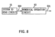
- the same advantage as the above-mentioned can be obtained by using a numerical operation circuit 50 constituted with, for example, a pseudo-random-number generation circuit, converting system ID number data S30 output from a system ID read circuit 51 with the numerical operation circuit 50 by the number of bits, and outputting system ID number data S31 which is the above operation result to the exclusive-OR circuits 5 and 12 as shown in Fig. 8.
- a numerical operation circuit 50 constituted with, for example, a pseudo-random-number generation circuit, converting system ID number data S30 output from a system ID read circuit 51 with the numerical operation circuit 50 by the number of bits, and outputting system ID number data S31 which is the above operation result to the exclusive-OR circuits 5 and 12 as shown in Fig. 8.
- the above embodiment has been dealt with a case where the convolution-encoding circuit 20 is set to the rear stage of the exclusive-OR circuit 5 and the Viterbi-decoding circuit 47 is set to the front stage of the exclusive-OR circuit 12.
- the present invention is not limited to this. It is possible to obtain the same advantage as the above-mentioned by setting a convolution-encoding circuit to the front stage of the exclusive-OR circuit 5 and setting a Viterbi-decoding circuit to the rear stage of the exclusive-OR circuit 12.
- the above embodiment has been dealt with a case where an exclusive OR is computed twice with the exclusive-OR circuit 5 of the transmitter 2 and the exclusive-OR circuit 12 of the receiver 3.
- the present invention is not limited to the above case. In short, it is possible to use a logical operation circuit for restoring the original transmission data S2 by performing logical operation twice. Also in this case, it is possible to obtain the same advantage as the above-mentioned.
- the above embodiment has been dealt with a case where a CRC code is added to the transmission data S1.
- the present invention is not limited to the above case. It is also possible to obtain the same advantage as the above-mentioned by adding one of various other error detection codes including parity bits.
- the above embodiment has been dealt with a case where the OFDM method is used as a modulation method.
- the present invention is not limited to the above case. It is also possible to obtain the advantage same as the above-mentioned by using one of various other modulation methods including the time division multiple access (TDMA) method and code division multiple access (CDMA) method.
- TDMA time division multiple access
- CDMA code division multiple access
- the present invention makes it possible to perform enciphering and certifying without increasing communications traffic because it is unnecessary to add and transmit identification-number data because of assigning the same identification-number data to a transmitter and a receiver, performing the logical operation using identification-number data in a transmitter and a receiver and detecting an error in the operation results.
- identification-number data because of assigning the same identification-number data to a transmitter and a receiver, performing the logical operation using identification-number data in a transmitter and a receiver and detecting an error in the operation results.
Landscapes
- Engineering & Computer Science (AREA)
- Computer Networks & Wireless Communication (AREA)
- Signal Processing (AREA)
- Detection And Prevention Of Errors In Transmission (AREA)
- Small-Scale Networks (AREA)
- Transmitters (AREA)
- Circuits Of Receivers In General (AREA)
Applications Claiming Priority (2)
| Application Number | Priority Date | Filing Date | Title |
|---|---|---|---|
| JP9367565A JPH11196070A (ja) | 1997-12-27 | 1997-12-27 | 送信装置、受信装置及び通信システム並びに通信方法 |
| JP36756597 | 1997-12-27 |
Publications (2)
| Publication Number | Publication Date |
|---|---|
| EP0926856A2 true EP0926856A2 (de) | 1999-06-30 |
| EP0926856A3 EP0926856A3 (de) | 2001-10-17 |
Family
ID=18489630
Family Applications (1)
| Application Number | Title | Priority Date | Filing Date |
|---|---|---|---|
| EP98310598A Withdrawn EP0926856A3 (de) | 1997-12-27 | 1998-12-22 | Unterdrückung von Übersprechen in einem Funknetzwerk |
Country Status (4)
| Country | Link |
|---|---|
| US (1) | US6346874B1 (de) |
| EP (1) | EP0926856A3 (de) |
| JP (1) | JPH11196070A (de) |
| CN (1) | CN1228647A (de) |
Cited By (2)
| Publication number | Priority date | Publication date | Assignee | Title |
|---|---|---|---|---|
| WO2000065765A1 (en) * | 1999-04-26 | 2000-11-02 | Nokia Networks Oy | New method for checking the data |
| CN100418312C (zh) * | 2005-06-30 | 2008-09-10 | 英业达股份有限公司 | 数字数据传输检错方法及系统 |
Families Citing this family (19)
| Publication number | Priority date | Publication date | Assignee | Title |
|---|---|---|---|---|
| US6839325B2 (en) * | 2000-06-09 | 2005-01-04 | Texas Instruments Incorporated | Wireless communication system which uses ARQ packets to ACK a plurality of packets from an 802.15 superpacket |
| US6748566B1 (en) * | 2000-07-21 | 2004-06-08 | Lucent Technologies Inc. | Ensuring proper acceptance of data at a receiver in wireless multiple access communications systems |
| US6760773B1 (en) | 2000-07-31 | 2004-07-06 | Lite-On Technology Corporation | Infrared transmission codes for wireless keyboard and PC remote controller |
| AU2005239706B2 (en) * | 2001-05-14 | 2007-11-15 | Intel Corporation | Method and system for implicit user equipment identification |
| US6915473B2 (en) | 2001-05-14 | 2005-07-05 | Interdigital Technology Corporation | Method and system for implicit user equipment identification |
| US7289476B2 (en) * | 2001-10-16 | 2007-10-30 | Nokia Corporation | Method and system to increase QoS and range in a multicarrier system |
| JP2004260708A (ja) * | 2003-02-27 | 2004-09-16 | Mitsumi Electric Co Ltd | 通信システム及び通信装置 |
| US7200405B2 (en) | 2003-11-18 | 2007-04-03 | Interdigital Technology Corporation | Method and system for providing channel assignment information used to support uplink and downlink channels |
| US7852822B2 (en) * | 2004-12-22 | 2010-12-14 | Qualcomm Incorporated | Wide area and local network ID transmission for communication systems |
| US8547843B2 (en) * | 2006-01-20 | 2013-10-01 | Saisei Networks Pte Ltd | System, method, and computer program product for controlling output port utilization |
| US20070171825A1 (en) * | 2006-01-20 | 2007-07-26 | Anagran, Inc. | System, method, and computer program product for IP flow routing |
| US8028217B2 (en) * | 2006-10-30 | 2011-09-27 | Interdigital Technology Corporation | Method and apparatus for encoding and decoding high speed shared control channel |
| US7555685B2 (en) * | 2006-11-21 | 2009-06-30 | Verizon Services Corp. | Method and apparatus for monitoring bit-error rate |
| JP5041851B2 (ja) * | 2007-04-02 | 2012-10-03 | 三菱電機株式会社 | データ送信装置、データ受信装置及びofdm通信システム |
| CN101111033B (zh) * | 2007-08-31 | 2013-10-02 | 华为技术有限公司 | 串话检测方法、网络侧设备及终端 |
| CN101123483B (zh) * | 2007-09-11 | 2010-11-24 | 华为技术有限公司 | 业务链路的检测方法及装置 |
| JP5772311B2 (ja) * | 2011-07-05 | 2015-09-02 | 富士通株式会社 | 情報処理装置及び情報処理方法 |
| JP2013046148A (ja) * | 2011-08-23 | 2013-03-04 | Tokai Rika Co Ltd | 通信方法及び通信システム、送信装置及び受信装置、並びにタイヤ空気圧監視システム |
| JP6712242B2 (ja) * | 2017-03-21 | 2020-06-17 | Kddi株式会社 | サーバ装置とビーコン装置とを含むシステムのサーバ装置及びプログラム |
Family Cites Families (11)
| Publication number | Priority date | Publication date | Assignee | Title |
|---|---|---|---|---|
| GB1448178A (en) * | 1973-12-14 | 1976-09-02 | Standard Telephones Cables Ltd | Error detection and correction in data transmission |
| US5668803A (en) * | 1989-06-29 | 1997-09-16 | Symbol Technologies, Inc. | Protocol for packet data communication system |
| US5068854A (en) * | 1989-09-12 | 1991-11-26 | Cupertino, California U.S.A. | Error detection for fiber distributed interfaced optic link |
| JP3088497B2 (ja) * | 1991-08-08 | 2000-09-18 | 松下電器産業株式会社 | 個別選択呼出受信装置 |
| EP0605996B1 (de) * | 1993-01-07 | 2000-01-19 | Ford Motor Company Limited | Ferngesteuertes Sicherheitssystem |
| JP2875448B2 (ja) * | 1993-03-17 | 1999-03-31 | 松下電器産業株式会社 | データ転送装置及びマルチプロセッサシステム |
| US5892924A (en) * | 1996-01-31 | 1999-04-06 | Ipsilon Networks, Inc. | Method and apparatus for dynamically shifting between routing and switching packets in a transmission network |
| US5931967A (en) * | 1996-02-22 | 1999-08-03 | Fujitsu, Ltd. | Method and apparatus for detection of errors in multiple-word communications |
| CA2208660C (en) * | 1996-07-19 | 2002-09-17 | Takashi Suzuki | Data transmission device |
| JPH10303866A (ja) * | 1997-04-28 | 1998-11-13 | Sony Corp | 受信装置及び受信方法 |
| FR2767618B1 (fr) * | 1997-08-25 | 1999-12-24 | Canon Kk | Procedes et dispositifs d'emission et de reception de donnees et systemes les utilisant |
-
1997
- 1997-12-27 JP JP9367565A patent/JPH11196070A/ja active Pending
-
1998
- 1998-12-22 EP EP98310598A patent/EP0926856A3/de not_active Withdrawn
- 1998-12-23 US US09/219,842 patent/US6346874B1/en not_active Expired - Fee Related
- 1998-12-24 CN CN98111666.3A patent/CN1228647A/zh active Pending
Cited By (2)
| Publication number | Priority date | Publication date | Assignee | Title |
|---|---|---|---|---|
| WO2000065765A1 (en) * | 1999-04-26 | 2000-11-02 | Nokia Networks Oy | New method for checking the data |
| CN100418312C (zh) * | 2005-06-30 | 2008-09-10 | 英业达股份有限公司 | 数字数据传输检错方法及系统 |
Also Published As
| Publication number | Publication date |
|---|---|
| EP0926856A3 (de) | 2001-10-17 |
| US6346874B1 (en) | 2002-02-12 |
| JPH11196070A (ja) | 1999-07-21 |
| CN1228647A (zh) | 1999-09-15 |
Similar Documents
| Publication | Publication Date | Title |
|---|---|---|
| US6346874B1 (en) | Transmitter and receiver, and communication system and communication method | |
| EP0599632B1 (de) | Gerät und Verfahren für drahtlose Kommunikation | |
| CA2470782C (en) | Framing structure for digital broadcasting and interactive services | |
| KR100770010B1 (ko) | 고속 데이터 전송을 위한 인체통신 시스템 | |
| US6414986B1 (en) | Method and system for radio communication | |
| EP0722227A1 (de) | Spreizspektrumdiversitysender/-empfänger | |
| JPH1032557A (ja) | 中継方式及びこれに用いる送信装置及び中継装置 | |
| US7173979B1 (en) | Method and device for transmitting information symbols using a plurality of carriers and method and device for receiving information symbols | |
| JP4099592B2 (ja) | 通信システム、送信装置および受信装置 | |
| KR100480268B1 (ko) | 직교 주파수 분할 다중 시스템의 피크전력 대 평균전력 비 감소를 위한 장치 및 방법 | |
| US5999570A (en) | Transmission apparatus, sending apparatus, and receiving apparatus, and transmission method | |
| JPH10308717A (ja) | 受信装置および受信方法 | |
| US8396219B2 (en) | Scrambler, scramble processing method, and program | |
| US7180962B2 (en) | Apparatus and method for demodulation using detection of channel adaptive modulation scheme | |
| JP2002247003A (ja) | 直交周波数分割多重変調方式を用いた伝送装置 | |
| EP0892517A2 (de) | Fehlerkorrekturkodierung für kurze Folgen | |
| US5724382A (en) | Multimode spread spectrum communication system tolerant to varying channel characteristics | |
| EP1604501B1 (de) | Mehrträgersystem, worin steuerdaten zu informationsdaten summiert werden | |
| US20090074101A1 (en) | Detection Performance in Communication Systems | |
| CN119834927A (zh) | 一种无线通信的方法及相关设备 | |
| JP3446816B2 (ja) | クロック情報を伴う信号伝送方法 | |
| Goodman et al. | Data transmission with variable-redundancy error control over a high-frequency channel | |
| JP2883238B2 (ja) | 符号化変調装置および復調装置 | |
| JPH09172391A (ja) | スペクトラム拡散通信方式 | |
| JP2002094486A (ja) | ワイヤレス多重アクセス通信システムとそれに用いられる送信器および受信器内で使用される装置 |
Legal Events
| Date | Code | Title | Description |
|---|---|---|---|
| PUAI | Public reference made under article 153(3) epc to a published international application that has entered the european phase |
Free format text: ORIGINAL CODE: 0009012 |
|
| AK | Designated contracting states |
Kind code of ref document: A2 Designated state(s): AT BE CH CY DE DK ES FI FR GB GR IE IT LI LU MC NL PT SE Kind code of ref document: A2 Designated state(s): DE FR GB |
|
| AX | Request for extension of the european patent |
Free format text: AL;LT;LV;MK;RO;SI |
|
| PUAL | Search report despatched |
Free format text: ORIGINAL CODE: 0009013 |
|
| AK | Designated contracting states |
Kind code of ref document: A3 Designated state(s): AT BE CH CY DE DK ES FI FR GB GR IE IT LI LU MC NL PT SE |
|
| AX | Request for extension of the european patent |
Free format text: AL;LT;LV;MK;RO;SI |
|
| RIC1 | Information provided on ipc code assigned before grant |
Free format text: 7H 04L 1/00 A, 7H 04L 27/26 B |
|
| 17P | Request for examination filed |
Effective date: 20020320 |
|
| AKX | Designation fees paid |
Free format text: DE FR GB |
|
| 17Q | First examination report despatched |
Effective date: 20050201 |
|
| STAA | Information on the status of an ep patent application or granted ep patent |
Free format text: STATUS: THE APPLICATION IS DEEMED TO BE WITHDRAWN |
|
| 18D | Application deemed to be withdrawn |
Effective date: 20050614 |