EP0926856A2 - Crosstalk suppression in a radio network - Google Patents
Crosstalk suppression in a radio network Download PDFInfo
- Publication number
- EP0926856A2 EP0926856A2 EP98310598A EP98310598A EP0926856A2 EP 0926856 A2 EP0926856 A2 EP 0926856A2 EP 98310598 A EP98310598 A EP 98310598A EP 98310598 A EP98310598 A EP 98310598A EP 0926856 A2 EP0926856 A2 EP 0926856A2
- Authority
- EP
- European Patent Office
- Prior art keywords
- data
- identification
- number data
- transmission
- reception
- Prior art date
- Legal status (The legal status is an assumption and is not a legal conclusion. Google has not performed a legal analysis and makes no representation as to the accuracy of the status listed.)
- Withdrawn
Links
Images
Classifications
-
- H—ELECTRICITY
- H04—ELECTRIC COMMUNICATION TECHNIQUE
- H04L—TRANSMISSION OF DIGITAL INFORMATION, e.g. TELEGRAPHIC COMMUNICATION
- H04L1/00—Arrangements for detecting or preventing errors in the information received
- H04L1/004—Arrangements for detecting or preventing errors in the information received by using forward error control
- H04L1/0041—Arrangements at the transmitter end
-
- H—ELECTRICITY
- H04—ELECTRIC COMMUNICATION TECHNIQUE
- H04L—TRANSMISSION OF DIGITAL INFORMATION, e.g. TELEGRAPHIC COMMUNICATION
- H04L1/00—Arrangements for detecting or preventing errors in the information received
- H04L1/004—Arrangements for detecting or preventing errors in the information received by using forward error control
- H04L1/0056—Systems characterized by the type of code used
- H04L1/0061—Error detection codes
-
- H—ELECTRICITY
- H04—ELECTRIC COMMUNICATION TECHNIQUE
- H04L—TRANSMISSION OF DIGITAL INFORMATION, e.g. TELEGRAPHIC COMMUNICATION
- H04L27/00—Modulated-carrier systems
- H04L27/26—Systems using multi-frequency codes
- H04L27/2601—Multicarrier modulation systems
Definitions
- This invention relates to a transmitter, a receiver, and a communication system and a communication method, and more particularly, is applicable to a radio network system for radio-transmitting digital data.
- the radio network system includes a system for radio-transmitting digital data such as image data between an AV (Audio Video) unit sets and a PC (Personal Computer) in a house or company.
- the radio network system realizes multi carrier transmission by using an orthogonal-frequency-division multiplexing system referred to as the orthogonal frequency division multiplex (OFDM) system as a modulation system.
- OFDM orthogonal frequency division multiplex
- an object of this invention is to provide a transmitter, a receiver, and a communication system and communication method capable of avoiding crosstalk with a simple structure.
- the foregoing object and other objects of the invention have been achieved by the provision of a transmitter for transmitting input data after applying predetermined data processing to the input data.
- the transmitter comprises: error-detection-code addition means for adding an error detection code to the input data; logical operation means for generating transmission data by applying the logical operation between the output data output from the error-detection-code addition means and the identification-number data assigned to the transmitter to the transmission data; and transmission means for transmitting the transmission data after applying predetermined transmission processing to the transmission data.
- this invention provides a receiver for receiving a transmission signal transmitted from a transmitter.
- the receiver comprises: reception means for receiving the transmission signal; logical operation means for performing the logical operation between the reception data received by the reception means and the identification-number data assigned to the receiver; and error detection means for detecting an error in the output data in accordance with an error detection code added to the output data output from the logical operation means and disusing the output data when the error is detected.
- this invention provides a communication system for performing communication between a transmitter and a receiver.
- the transmitter has error-detection-code addition means for adding an error detection code to input data, first logical operation means for generating transmission data by performing the logical operation between the first output data output from the error-detection-code addition means and the first identification-number data assigned to the transmitter, and transmission means for transmitting a transmission signal generated by applying predetermined transmission processing to the transmission data.
- the receiver has reception means for receiving the transmission signal, second logical operation means for performing the logical operation between reception data received by the reception means and the second identification-number data assigned to the receiver and same as the first identification-number data, and error detection means for detecting an error in the second output data in accordance with the error detection code added to the second output data output from the second logical operation means and disusing the second output data when the error is detected.
- this invention provides a communication method, which comprises the steps of: generating the first output data by adding an error detection code to input data; generating transmission data by performing the logical operation between the first output data and the first identification-number data; generating and transmitting a transmission signal by applying predetermined transmission processing to the transmission data; generating the second output data by performing the logical operation between reception data obtained by receiving the transmission signal and the second identification-number data same as the first identification-number data; and detecting an error in the second output data in accordance with an error detection code added to the second output data and disusing the second output data when the error is detected.
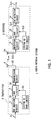
- symbol 1 denotes a radio network system to which the present invention is applied, which has a transmitter 2 and a receiver 3.
- the transmitter 2 and the receiver 3 are mounted on an AV unit or PC set in a house or company and used for the communication between AV units, the communication from an AV unit to a PC, or the communication from a PC to an AV unit.
- the transmitter 2 inputs transmission data S1 supplied through a predetermined data processing circuit to a cyclic redundancy check (CRC) addition circuit 4.
- the CRC addition circuit 4 adds a CRC code to the transmission data S1 every predetermined number of bits and outputs transmission data S2 thereby obtained to an exclusive-OR (XOR) circuit 5.
- XOR exclusive-OR
- a system ID number peculiar to the radio network system 1 to which the transmitter 2 belongs is previously set to the transmitter 2 and stored in, for example, storage means such as an integrated circuit (IC) card.
- a system ID read circuit 6 reads a system ID number from the storage means and outputs the system ID number to the exclusive-OR circuit 5 as system ID number data S3.
- the exclusive-OR circuit 5 computes the exclusive OR between the transmission data S2 and the system ID number data S3 every predetermined number of bits as described above and outputs transmission data S4 thereby obtained to a transmission circuit 7.
- the transmission circuit 7 performs the multicarrier modulation processing according to the OFDM method to generate transmission signal S5, and supplies the signal S5 to an antenna 8. Thereby, the transmission signal S5 is transmitted through the antenna 8.
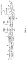
- the receiver 3 inputs reception signal S10 received by the antenna 10 to a reception circuit 11.
- the reception circuit 11 performs a predetermined demodulation processing according to the OFDM method to generate reception data S11, and outputs the data S11 to an exclusive-OR circuit 12.
- a system ID number is previously set to the receiver 3 similarly to the case of the transmitter 2 and stored in storage means.
- a system ID read circuit 13 reads the system ID number and outputs the ID number to the exclusive-OR circuit 12 as system ID number data S12.
- the exclusive-OR circuit 12 computes the exclusive OR between the reception data S11 and the system ID number data S12 every predetermined number of bits and outputs the reception data S13 thereby obtained to a CRC detection circuit 14.
- the CRC detection circuit 14 detects an error in the reception data S13 by using a CRC code and outputs reception data S14 thereby obtained to a predetermined data processing circuit provided at the rear stage.
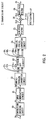
- the structure of the transmission circuit 7 is described below by referring to Fig. 2.
- the transmission circuit 7 inputs the transmission data S4 output from the exclusive-OR circuit 5 to a convolution-encoding circuit 20.
- the convolution-encoding circuit 20 convolution-encodes the transmission data S4 and outputs the transmission data S5 thereby obtained to a Quadrature phase shift keying (QPSK modulation) circuit 21.
- QPSK modulation Quadrature phase shift keying
- the QPSK modulation circuit 21 QPSK-modulates the transmission data S5 and outputs transmission signal S6 thereby obtained to a serial-parallel conversion circuit 22.
- the serial-parallel conversion circuit 22 converts the transmission signal S6 supplied in the form of a serial data string into transmission signals S7 1 to S7 N of a parallel data string and outputs the signals S7 1 to S7 N to an inverse fast Fourier transform (inverse FFT) circuit 23.
- the inverse fast Fourier transform circuit 23 applies the inverse fast Fourier transform to the transmission signals S7 1 to S7 N to map the transmission signals S7 1 to S7 N to frequency-region data, and outputs transmission signals S8 1 to S8 N thereby obtained to a parallel-serial conversion circuit 24.
- the parallel-serial conversion circuit 24 converts the transmission signals S8 1 to S8 N supplied in the form of a parallel data string into a serial data string and outputs transmission signal S9 thereby obtained to a low-pass filter 25.
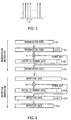
- Fig. 3 shows a spectrum of a carrier waveform of the OFDM method.
- the transmission signal S6 is assigned to subcarriers perpendicularly intersecting each other at a frequency interval of f 0 to transmit the transmission signal S6.
- the OFDM method parallel-converts the transmission signal S6, applies the inverse fast Fourier transform to the parallel-converted transmission signals S7 1 to S7 N , and thereby assigns the transmission signals S7 1 to S7 N to subcarriers.
- the method fetches the data assigned to the subcarriers by capturing signal components from the subcarriers every interval f 0 and performing the fast Fourier transform processing.
- the low-pass filter 25 removes unnecessary components and noises out of low frequencies from the transmission signal S9 and outputs the transmission signal S10 thereby obtained to a frequency conversion circuit 26.
- the frequency conversion circuit 26 multiplies the transmission signal S10 by a local oscillation signal S11 supplied from an oscillator 27 to generate transmission signal S12 frequency-converted into a predetermined frequency, and outputs the signal S12 to a band-pass filter 28.
- the band-pass filter 28 removes unnecessary components and noises out of the band from the transmission signal S12 and supplies the transmission signal S5 thereby obtained to the antenna 7.
- the reception circuit 11 inputs the reception signal S10 received through the antenna 10 to a band-pass filter 40.
- the band-pass filter 40 removes unnecessary components and noises out of the band from the reception signal S10 and outputs reception signal S20 thereby obtained to a frequency conversion circuit 41.
- the frequency conversion circuit 41 multiplies the reception signal S20 by the local oscillation signal S21 supplied from an oscillator 42 to generate intermediate-frequency reception signal S22, and outputs the signal S22 to a serial-parallel conversion circuit 43.
- the serial-parallel conversion circuit 43 parallel-converts the reception signal S22 and outputs reception signals S23 1 to S23 N thereby obtained to a fast Fourier transform (FFT) circuit 44.
- the fast Fourier transform circuit 44 applies the fast Fourier transform processing to the reception signals S23 1 to S23 N and outputs reception signals S24 1 to S24 N thereby obtained to a parallel-serial conversion circuit 45.
- the serial-parallel conversion circuit 45 converts the reception signals S24 1 to S24 N into reception signal S25 of a serial data string and outputs the signal S25 to a QPSK demodulation circuit 46.
- the serial-parallel conversion circuit 43, the fast Fourier transform circuit 44, and the parallel-serial conversion circuit 45 decode the reception signal S22 according to the OFDM method. That is, effective data is cut off by the serial-parallel conversion circuit 43 and a reception waveform is captured every interval f 0 and converted into parallel data.
- the output of the serial-parallel conversion circuit 43 is supplied to the fast Fourier transform circuit 44 and fast-Fourier-transformed.
- decoding according to the OFDM method is performed by fast-Fourier-transforming a waveform sampled every interval f 0 .
- the QPSK demodulation circuit 46 applies the QPSK demodulation processing to the reception signal S25 to restore the reception data S26, and outputs the reception data S26 to a Viterbi-decoding circuit 47.
- the Viterbi-decoding circuit 47 Viterbi-decodes the reception data S26 and outputs the reception data S11 thereby obtained to the exclusive-OR circuit 12.
- the CRC addition circuit 4 adds a CRC code to the reception data S1 every predetermined number of bits to generate the transmission data S2, and outputs the data S2 to the exclusive-OR circuit 5.
- the system ID read circuit 6 applies the data processing for equalizing the length of the system ID number data S3 with that of the transmission data S2 to the data S3 and then, outputs the system ID number data S3 to the exclusive-OR circuit 5.
- the system ID read circuit 6 When the length of the system ID number data S3 is smaller than that of the transmission data S2, for example, when the length of the system ID number data S3 is sixty-four bits and that of the transmission data S2 is sixty-seven bits, the system ID read circuit 6 generates the system ID number data S3 by combining three fixed bits "000" with the tail of the system ID number data S3 and equalizes the length of the system ID number data S3 with that of the transmission data S2, and thereafter outputs the system ID number data S3 to the exclusive-OR circuit 5.
- the exclusive-OR circuit 5 generates the transmission data S4 by computing the exclusive OR between the transmission data S2 and the system ID number data S3 every predetermined number of bits.
- the transmission circuit 7 applies a predetermined modulation processing to the transmission data S4 and then, the data S4 is transmitted through the antenna 8.
- the receiver 3 supplies the reception signal S10 received through the antenna 10 to the reception circuit 11 and applies a predetermined demodulation processing to the signal S10 through the reception circuit 11 and thereafter, outputs the signal S10 to the exclusive-OR circuit 12.
- the system ID read circuit 13 generates the system ID data S12 by inserting a fixed bit into the system ID number data S12 similarly to the case of the system ID read circuit 6 of the transmitter 2, equalizes the length of the system ID number data S12 with that of the reception data S11, and then outputs the system ID number data S12 to the exclusive-OR circuit 12.
- the exclusive-OR circuit 12 computes the exclusive OR between the reception data S11 and the system ID number data S12 every predetermined number of bits and outputs the reception data S13 thereby obtained to the CRC detection circuit 14.
- the CRC detection circuit 14 detects an error in the reception data S13 by using a CRC code and outputs the reception data S14 thereby obtained to a predetermined data processing circuit.
- step SP2 after entered from step SP1, the CRC addition circuit 4 adds a CRC code to the transmission data S1.
- the exclusive-OR circuit 5 computes the exclusive OR between the transmission data S2 to which a CRC code is added and the system ID number data S3 supplied from the system ID read circuit 6 and outputs the transmission data S4 thereby obtained to the transmission circuit 7.
- the transmission circuit 7 applies the multicarrier modulation processing to the transmission data S4 to generate the transmission signal S5, and transmits the signal S5 through the antenna 8. Then, the processing proceeds to step SP5 to be terminated.
- step SP11 after entered from step SP10, the reception circuit 11 applies the multicarrier demodulation processing to the reception signal S10 received through the antenna 10 to generate the reception data S11, and outputs the signal S10 to the exclusive-OR circuit 12.
- the exclusive-OR circuit 12 computes the exclusive OR between the reception data S11 and the system ID number data S3 supplied from the system ID read circuit 13 and outputs the reception data S13 thereby obtained to the CRC detection circuit 14.
- the CRC detection circuit 14 detects an error in the reception data S13 and outputs the reception data S14 thereby obtained to a data processing circuit at the rear stage. Then, the processing proceeds to step SP14 to be terminated.
- the exclusive-OR circuit 5 computes the exclusive OR between the transmission data S2 to which a CRC code is added and the system ID number data S3 peculiar to the radio network system 1 and transmits the transmission data S4 thereby obtained.
- the exclusive-OR circuit 12 computes the exclusive OR between the reception data S11 and the system ID number data S12 and outputs the reception data S13 thereby obtained to the CRC detection circuit 14.
- the CRC detection circuit 14 checks the reception data S13 for errors by using a CRC code and outputs the reception data S14 thereby obtained to a data processing circuit at the rear stage.
- the exclusive-OR circuit 12 computes an exclusive OR because the system ID number data S3 and S12 of the transmitter 2 and receiver 3 are the same. Thereby, an exclusive OR is computed for the transmission data S2 up to twice. Therefore, the exclusive-OR circuit 12 restores the reception data S13 same as the transmission data S2 of the transmitter 2 and outputs the data S13 to the CRC detection circuit 14.
- the CRC detection circuit 14 generates the reception data S14 by checking the reception data S13 for errors by using a CRC code and outputs the reception data S14.
- the receiver 3 when receiving a transmission signal from a transmitter belonging to other radio network system, the receiver 3 cannot restore original transmission data even if an exclusive OR is computed by the exclusive-OR circuit 12 because the system ID number data S12 is different from the system ID number data of the transmitter. Therefore, the exclusive-OR circuit 12 generates the reception data S13 different from the original transmission data and outputs the data S13 to the CRC detection circuit 14.
- the CRC detection circuit 14 checks the reception data S13 for errors by using a CRC code and then, disuses the data S13 because of deciding that a transmission error occurs in the reception data S13.
- the receiver 3 cannot restore the original transmission data S2 when it does not have the system ID number data S12 same as the system ID number data S3 of the transmitter 2. Therefore, the transmitter 2 can perform enciphering using a system ID number peculiar to a network as a key by computing the exclusive OR between the transmission data S2 and the system ID number data S3. Moreover, the receiver 3 can certify the transmitter 2 by computing the exclusive OR between the reception data S11 and the system ID number data S12.
- the transmitter 2 can perform enciphering without increasing communications traffic because it is unnecessary to transmit the system ID number data S3 serving as a key by adding it to the transmission data S2 and secure communication safety. Therefore, it is possible to prevent illegal access and illegal interception.
- the receiver 3 can certify a communication counterpart without increasing communications traffic because it is unnecessary to add a system ID number to the transmission data S2 at the transmitter-2 side. Therefore, it is possible to prevent erroneous connection and avoid crosstalk.
- the present invention is not limited to this, but it is possible to obtain the same advantage as the above-mentioned by combining a fixed bit with the heads of the system ID number data S3 and S12 or inserting a fixed bit into the middles of the system ID number data S3 and S12 and then computing an exclusive OR. In short, it is possible to compute an exclusive OR after equalizing the lengths of the system ID number data S3 and S12 with those of the transmission data S2 and the reception data S11.
- the above embodiment has been dealt with a case where a fixed bit is combined with or inserted into the system ID number data S3 and S12 by the system ID read circuits 6 and 13.
- the present invention is not limited to this.
- the above embodiment has been dealt with a case where the lengths of the system ID number data S3 and S12 are equalized with those of the transmission data S2 and the reception data S11 by combining a fixed bit with the system ID number data S3 and S12 when the lengths of the system ID number data S3 and S12 are smaller than those of the transmission data S2 and the reception data S11.
- the present invention is not limited to this.
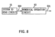
- the same advantage as the above-mentioned can be obtained by using a numerical operation circuit 50 constituted with, for example, a pseudo-random-number generation circuit, converting system ID number data S30 output from a system ID read circuit 51 with the numerical operation circuit 50 by the number of bits, and outputting system ID number data S31 which is the above operation result to the exclusive-OR circuits 5 and 12 as shown in Fig. 8.
- a numerical operation circuit 50 constituted with, for example, a pseudo-random-number generation circuit, converting system ID number data S30 output from a system ID read circuit 51 with the numerical operation circuit 50 by the number of bits, and outputting system ID number data S31 which is the above operation result to the exclusive-OR circuits 5 and 12 as shown in Fig. 8.
- the above embodiment has been dealt with a case where the convolution-encoding circuit 20 is set to the rear stage of the exclusive-OR circuit 5 and the Viterbi-decoding circuit 47 is set to the front stage of the exclusive-OR circuit 12.
- the present invention is not limited to this. It is possible to obtain the same advantage as the above-mentioned by setting a convolution-encoding circuit to the front stage of the exclusive-OR circuit 5 and setting a Viterbi-decoding circuit to the rear stage of the exclusive-OR circuit 12.
- the above embodiment has been dealt with a case where an exclusive OR is computed twice with the exclusive-OR circuit 5 of the transmitter 2 and the exclusive-OR circuit 12 of the receiver 3.
- the present invention is not limited to the above case. In short, it is possible to use a logical operation circuit for restoring the original transmission data S2 by performing logical operation twice. Also in this case, it is possible to obtain the same advantage as the above-mentioned.
- the above embodiment has been dealt with a case where a CRC code is added to the transmission data S1.
- the present invention is not limited to the above case. It is also possible to obtain the same advantage as the above-mentioned by adding one of various other error detection codes including parity bits.
- the above embodiment has been dealt with a case where the OFDM method is used as a modulation method.
- the present invention is not limited to the above case. It is also possible to obtain the advantage same as the above-mentioned by using one of various other modulation methods including the time division multiple access (TDMA) method and code division multiple access (CDMA) method.
- TDMA time division multiple access
- CDMA code division multiple access
- the present invention makes it possible to perform enciphering and certifying without increasing communications traffic because it is unnecessary to add and transmit identification-number data because of assigning the same identification-number data to a transmitter and a receiver, performing the logical operation using identification-number data in a transmitter and a receiver and detecting an error in the operation results.
- identification-number data because of assigning the same identification-number data to a transmitter and a receiver, performing the logical operation using identification-number data in a transmitter and a receiver and detecting an error in the operation results.
Abstract
Description
- This invention relates to a transmitter, a receiver, and a communication system and a communication method, and more particularly, is applicable to a radio network system for radio-transmitting digital data.
- The radio network system includes a system for radio-transmitting digital data such as image data between an AV (Audio Video) unit sets and a PC (Personal Computer) in a house or company. The radio network system realizes multi carrier transmission by using an orthogonal-frequency-division multiplexing system referred to as the orthogonal frequency division multiplex (OFDM) system as a modulation system.
- In the case of this type of radio communication system, crosstalk may occur due to the fact that radio waves of adjacent other network reach the network of its own. Therefore, to avoid the crosstalk, a method is considered which avoids the fact that radio waves of other network are erroneously connected by adding a network ID (Identification) to radio waves to transmit it and identifying radio waves belonging to a network by the network ID. However, this method has a problem that the overhead occurs that the communications traffic of transmission data increases because it is necessary to add a network ID to the transmission data.
- In view of the foregoing, an object of this invention is to provide a transmitter, a receiver, and a communication system and communication method capable of avoiding crosstalk with a simple structure.
- The foregoing object and other objects of the invention have been achieved by the provision of a transmitter for transmitting input data after applying predetermined data processing to the input data. The transmitter comprises: error-detection-code addition means for adding an error detection code to the input data; logical operation means for generating transmission data by applying the logical operation between the output data output from the error-detection-code addition means and the identification-number data assigned to the transmitter to the transmission data; and transmission means for transmitting the transmission data after applying predetermined transmission processing to the transmission data.
- Further, this invention provides a receiver for receiving a transmission signal transmitted from a transmitter. The receiver comprises: reception means for receiving the transmission signal; logical operation means for performing the logical operation between the reception data received by the reception means and the identification-number data assigned to the receiver; and error detection means for detecting an error in the output data in accordance with an error detection code added to the output data output from the logical operation means and disusing the output data when the error is detected.
- Further, this invention provides a communication system for performing communication between a transmitter and a receiver. In the communication system, the transmitter has error-detection-code addition means for adding an error detection code to input data, first logical operation means for generating transmission data by performing the logical operation between the first output data output from the error-detection-code addition means and the first identification-number data assigned to the transmitter, and transmission means for transmitting a transmission signal generated by applying predetermined transmission processing to the transmission data. Also, in the communication system, the receiver has reception means for receiving the transmission signal, second logical operation means for performing the logical operation between reception data received by the reception means and the second identification-number data assigned to the receiver and same as the first identification-number data, and error detection means for detecting an error in the second output data in accordance with the error detection code added to the second output data output from the second logical operation means and disusing the second output data when the error is detected.
- Further, this invention provides a communication method, which comprises the steps of: generating the first output data by adding an error detection code to input data; generating transmission data by performing the logical operation between the first output data and the first identification-number data; generating and transmitting a transmission signal by applying predetermined transmission processing to the transmission data; generating the second output data by performing the logical operation between reception data obtained by receiving the transmission signal and the second identification-number data same as the first identification-number data; and detecting an error in the second output data in accordance with an error detection code added to the second output data and disusing the second output data when the error is detected.
- The invention will further be described by way of example with reference to the accompanying drawings in which like parts are designated by like reference numerals or characters; and in which:-
- Fig. 1 is a block diagram showing the structure of the radio network system according to an embodiment of the present invention;
- Fig. 2 is a block diagram showing the structure of a transmission circuit;
- Fig. 3 is a schematic diagram showing subcarriers according to the OFDM method;
- Fig. 4 is a block diagram showing the structure of a receiver;
- Fig. 5 is a schematic diagram showing the data processing by a radio network system;
- Fig. 6 is a flowchart showing the data processing procedure by a transmitter;
- Fig. 7 is a flowchart showing the data processing procedure by a receiver; and
- Fig. 8 is a block diagram showing number-of-bits conversion processing.
-
- Preferred embodiments of this invention will be described with reference to the accompanying drawings:
- In Fig. 1,
symbol 1 denotes a radio network system to which the present invention is applied, which has atransmitter 2 and areceiver 3. Thetransmitter 2 and thereceiver 3 are mounted on an AV unit or PC set in a house or company and used for the communication between AV units, the communication from an AV unit to a PC, or the communication from a PC to an AV unit. - The
transmitter 2 inputs transmission data S1 supplied through a predetermined data processing circuit to a cyclic redundancy check (CRC)addition circuit 4. TheCRC addition circuit 4 adds a CRC code to the transmission data S1 every predetermined number of bits and outputs transmission data S2 thereby obtained to an exclusive-OR (XOR)circuit 5. - A system ID number peculiar to the
radio network system 1 to which thetransmitter 2 belongs is previously set to thetransmitter 2 and stored in, for example, storage means such as an integrated circuit (IC) card. A system ID readcircuit 6 reads a system ID number from the storage means and outputs the system ID number to the exclusive-OR circuit 5 as system ID number data S3. - The exclusive-
OR circuit 5 computes the exclusive OR between the transmission data S2 and the system ID number data S3 every predetermined number of bits as described above and outputs transmission data S4 thereby obtained to atransmission circuit 7. Thetransmission circuit 7 performs the multicarrier modulation processing according to the OFDM method to generate transmission signal S5, and supplies the signal S5 to an antenna 8. Thereby, the transmission signal S5 is transmitted through the antenna 8. - The
receiver 3 inputs reception signal S10 received by theantenna 10 to areception circuit 11. Thereception circuit 11 performs a predetermined demodulation processing according to the OFDM method to generate reception data S11, and outputs the data S11 to an exclusive-OR circuit 12. A system ID number is previously set to thereceiver 3 similarly to the case of thetransmitter 2 and stored in storage means. A system ID readcircuit 13 reads the system ID number and outputs the ID number to the exclusive-OR circuit 12 as system ID number data S12. - The exclusive-
OR circuit 12 computes the exclusive OR between the reception data S11 and the system ID number data S12 every predetermined number of bits and outputs the reception data S13 thereby obtained to aCRC detection circuit 14. TheCRC detection circuit 14 detects an error in the reception data S13 by using a CRC code and outputs reception data S14 thereby obtained to a predetermined data processing circuit provided at the rear stage. - The structure of the
transmission circuit 7 is described below by referring to Fig. 2. Thetransmission circuit 7 inputs the transmission data S4 output from the exclusive-OR circuit 5 to a convolution-encoding circuit 20. The convolution-encoding circuit 20 convolution-encodes the transmission data S4 and outputs the transmission data S5 thereby obtained to a Quadrature phase shift keying (QPSK modulation)circuit 21. - The
QPSK modulation circuit 21 QPSK-modulates the transmission data S5 and outputs transmission signal S6 thereby obtained to a serial-parallel conversion circuit 22. The serial-parallel conversion circuit 22 converts the transmission signal S6 supplied in the form of a serial data string into transmission signals S71 to S7N of a parallel data string and outputs the signals S71 to S7N to an inverse fast Fourier transform (inverse FFT)circuit 23. The inverse fast Fouriertransform circuit 23 applies the inverse fast Fourier transform to the transmission signals S71 to S7N to map the transmission signals S71 to S7N to frequency-region data, and outputs transmission signals S81 to S8N thereby obtained to a parallel-serial conversion circuit 24. The parallel-serial conversion circuit 24 converts the transmission signals S81 to S8N supplied in the form of a parallel data string into a serial data string and outputs transmission signal S9 thereby obtained to a low-pass filter 25. - In this case, the serial-
parallel conversion circuit 22, inverse fast Fouriertransform circuit 23, and parallel-serial conversion circuit 24 convert the transmission signal S6 into multicarrier signal according to the OFDM method. The OFDM method makes it possible to obtain a high bit rate as a whole by using a plurality of subcarriers in which carriers perpendicularly intersect each other at a frequency interval of f0 so that interference does not occur between codes and thereby assigning a low-bit-rate signal to each subcarrier. - Fig. 3 shows a spectrum of a carrier waveform of the OFDM method. As shown in Fig. 3, in the case of the OFDM method, the transmission signal S6 is assigned to subcarriers perpendicularly intersecting each other at a frequency interval of f0 to transmit the transmission signal S6.
- The OFDM method parallel-converts the transmission signal S6, applies the inverse fast Fourier transform to the parallel-converted transmission signals S71 to S7N, and thereby assigns the transmission signals S71 to S7N to subcarriers. In the case of decoding, however, the method fetches the data assigned to the subcarriers by capturing signal components from the subcarriers every interval f0 and performing the fast Fourier transform processing.
- In Fig. 2, the low-
pass filter 25 removes unnecessary components and noises out of low frequencies from the transmission signal S9 and outputs the transmission signal S10 thereby obtained to afrequency conversion circuit 26. Thefrequency conversion circuit 26 multiplies the transmission signal S10 by a local oscillation signal S11 supplied from an oscillator 27 to generate transmission signal S12 frequency-converted into a predetermined frequency, and outputs the signal S12 to a band-pass filter 28. The band-pass filter 28 removes unnecessary components and noises out of the band from the transmission signal S12 and supplies the transmission signal S5 thereby obtained to theantenna 7. - Then, the structure of the
reception circuit 11 is described below by referring to Fig. 4. Thereception circuit 11 inputs the reception signal S10 received through theantenna 10 to a band-pass filter 40. The band-pass filter 40 removes unnecessary components and noises out of the band from the reception signal S10 and outputs reception signal S20 thereby obtained to afrequency conversion circuit 41. Thefrequency conversion circuit 41 multiplies the reception signal S20 by the local oscillation signal S21 supplied from anoscillator 42 to generate intermediate-frequency reception signal S22, and outputs the signal S22 to a serial-parallel conversion circuit 43. - The serial-
parallel conversion circuit 43 parallel-converts the reception signal S22 and outputs reception signals S231 to S23N thereby obtained to a fast Fourier transform (FFT)circuit 44. The fast Fouriertransform circuit 44 applies the fast Fourier transform processing to the reception signals S231 to S23N and outputs reception signals S241 to S24N thereby obtained to a parallel-serial conversion circuit 45. The serial-parallel conversion circuit 45 converts the reception signals S241 to S24N into reception signal S25 of a serial data string and outputs the signal S25 to aQPSK demodulation circuit 46. - In this case, the serial-
parallel conversion circuit 43, the fastFourier transform circuit 44, and the parallel-serial conversion circuit 45 decode the reception signal S22 according to the OFDM method. That is, effective data is cut off by the serial-parallel conversion circuit 43 and a reception waveform is captured every interval f0 and converted into parallel data. The output of the serial-parallel conversion circuit 43 is supplied to the fastFourier transform circuit 44 and fast-Fourier-transformed. Thus, decoding according to the OFDM method is performed by fast-Fourier-transforming a waveform sampled every interval f0. - The
QPSK demodulation circuit 46 applies the QPSK demodulation processing to the reception signal S25 to restore the reception data S26, and outputs the reception data S26 to a Viterbi-decoding circuit 47. The Viterbi-decoding circuit 47 Viterbi-decodes the reception data S26 and outputs the reception data S11 thereby obtained to the exclusive-OR circuit 12. - The data processing by the
radio network system 1 is described below by referring to Fig. 5. In thetransmitter 2, theCRC addition circuit 4 adds a CRC code to the reception data S1 every predetermined number of bits to generate the transmission data S2, and outputs the data S2 to the exclusive-OR circuit 5. - However, if the length of the system ID number data S3 is different from that of the transmission data S2, the exclusive OR between the data S3 and S2 cannot be computed. Therefore, the system ID read
circuit 6 applies the data processing for equalizing the length of the system ID number data S3 with that of the transmission data S2 to the data S3 and then, outputs the system ID number data S3 to the exclusive-OR circuit 5. - When the length of the system ID number data S3 is smaller than that of the transmission data S2, for example, when the length of the system ID number data S3 is sixty-four bits and that of the transmission data S2 is sixty-seven bits, the system ID read
circuit 6 generates the system ID number data S3 by combining three fixed bits "000" with the tail of the system ID number data S3 and equalizes the length of the system ID number data S3 with that of the transmission data S2, and thereafter outputs the system ID number data S3 to the exclusive-OR circuit 5. - The exclusive-
OR circuit 5 generates the transmission data S4 by computing the exclusive OR between the transmission data S2 and the system ID number data S3 every predetermined number of bits. Thetransmission circuit 7 applies a predetermined modulation processing to the transmission data S4 and then, the data S4 is transmitted through the antenna 8. - The
receiver 3 supplies the reception signal S10 received through theantenna 10 to thereception circuit 11 and applies a predetermined demodulation processing to the signal S10 through thereception circuit 11 and thereafter, outputs the signal S10 to the exclusive-OR circuit 12. The system ID readcircuit 13 generates the system ID data S12 by inserting a fixed bit into the system ID number data S12 similarly to the case of the system ID readcircuit 6 of thetransmitter 2, equalizes the length of the system ID number data S12 with that of the reception data S11, and then outputs the system ID number data S12 to the exclusive-OR circuit 12. - The exclusive-
OR circuit 12 computes the exclusive OR between the reception data S11 and the system ID number data S12 every predetermined number of bits and outputs the reception data S13 thereby obtained to theCRC detection circuit 14. TheCRC detection circuit 14 detects an error in the reception data S13 by using a CRC code and outputs the reception data S14 thereby obtained to a predetermined data processing circuit. - Then, the data processing procedure by the
transmitter 2 is described below by referring to Fig. 6. First, at step SP2 after entered from step SP1, theCRC addition circuit 4 adds a CRC code to the transmission data S1. At step SP3, the exclusive-OR circuit 5 computes the exclusive OR between the transmission data S2 to which a CRC code is added and the system ID number data S3 supplied from the system ID readcircuit 6 and outputs the transmission data S4 thereby obtained to thetransmission circuit 7. At step SP4, thetransmission circuit 7 applies the multicarrier modulation processing to the transmission data S4 to generate the transmission signal S5, and transmits the signal S5 through the antenna 8. Then, the processing proceeds to step SP5 to be terminated. - Then, the data processing procedure by the
receiver 3 is described below by referring to Fig. 7. First, at step SP11 after entered from step SP10, thereception circuit 11 applies the multicarrier demodulation processing to the reception signal S10 received through theantenna 10 to generate the reception data S11, and outputs the signal S10 to the exclusive-OR circuit 12. At step SP12, the exclusive-OR circuit 12 computes the exclusive OR between the reception data S11 and the system ID number data S3 supplied from the system ID readcircuit 13 and outputs the reception data S13 thereby obtained to theCRC detection circuit 14. At step SP13, theCRC detection circuit 14 detects an error in the reception data S13 and outputs the reception data S14 thereby obtained to a data processing circuit at the rear stage. Then, the processing proceeds to step SP14 to be terminated. - According to the above structure, in the
transmitter 2, the exclusive-OR circuit 5 computes the exclusive OR between the transmission data S2 to which a CRC code is added and the system ID number data S3 peculiar to theradio network system 1 and transmits the transmission data S4 thereby obtained. In thereceiver 3, on the contrary to this, the exclusive-OR circuit 12 computes the exclusive OR between the reception data S11 and the system ID number data S12 and outputs the reception data S13 thereby obtained to theCRC detection circuit 14. TheCRC detection circuit 14 checks the reception data S13 for errors by using a CRC code and outputs the reception data S14 thereby obtained to a data processing circuit at the rear stage. - When the
receiver 3 receives the transmission signal S5 from thetransmitter 2 belonging to the sameradio network system 1, the exclusive-OR circuit 12 computes an exclusive OR because the system ID number data S3 and S12 of thetransmitter 2 andreceiver 3 are the same. Thereby, an exclusive OR is computed for the transmission data S2 up to twice. Therefore, the exclusive-OR circuit 12 restores the reception data S13 same as the transmission data S2 of thetransmitter 2 and outputs the data S13 to theCRC detection circuit 14. TheCRC detection circuit 14 generates the reception data S14 by checking the reception data S13 for errors by using a CRC code and outputs the reception data S14. - However, when receiving a transmission signal from a transmitter belonging to other radio network system, the
receiver 3 cannot restore original transmission data even if an exclusive OR is computed by the exclusive-OR circuit 12 because the system ID number data S12 is different from the system ID number data of the transmitter. Therefore, the exclusive-OR circuit 12 generates the reception data S13 different from the original transmission data and outputs the data S13 to theCRC detection circuit 14. TheCRC detection circuit 14 checks the reception data S13 for errors by using a CRC code and then, disuses the data S13 because of deciding that a transmission error occurs in the reception data S13. - Thus, the
receiver 3 cannot restore the original transmission data S2 when it does not have the system ID number data S12 same as the system ID number data S3 of thetransmitter 2. Therefore, thetransmitter 2 can perform enciphering using a system ID number peculiar to a network as a key by computing the exclusive OR between the transmission data S2 and the system ID number data S3. Moreover, thereceiver 3 can certify thetransmitter 2 by computing the exclusive OR between the reception data S11 and the system ID number data S12. - Thus, the
transmitter 2 can perform enciphering without increasing communications traffic because it is unnecessary to transmit the system ID number data S3 serving as a key by adding it to the transmission data S2 and secure communication safety. Therefore, it is possible to prevent illegal access and illegal interception. Moreover, thereceiver 3 can certify a communication counterpart without increasing communications traffic because it is unnecessary to add a system ID number to the transmission data S2 at the transmitter-2 side. Therefore, it is possible to prevent erroneous connection and avoid crosstalk. - According to the above structure, it is possible to perform enciphering and certifying without increasing communications traffic because it is unnecessary to transmit the transmission data S2 by adding a system ID number to the data S2 by computing the exclusive OR between the transmission data S2 and the system ID number data S3 with the
transmitter 2 and thereafter transmitting the data and computing the exclusive OR between the reception data S11 and the system ID number data S12 with thereceiver 3 and thereafter detecting errors. Thus, it is possible to avoid crosstalk with a simple structure. - The above described embodiment has been dealt with a case where a fixed bit is combined with the tails of the system ID number data S3 and S12. However, the present invention is not limited to this, but it is possible to obtain the same advantage as the above-mentioned by combining a fixed bit with the heads of the system ID number data S3 and S12 or inserting a fixed bit into the middles of the system ID number data S3 and S12 and then computing an exclusive OR. In short, it is possible to compute an exclusive OR after equalizing the lengths of the system ID number data S3 and S12 with those of the transmission data S2 and the reception data S11.
- Moreover, the above embodiment has been dealt with a case where a fixed bit is combined with or inserted into the system ID number data S3 and S12 by the system ID read
circuits OR circuits - Furthermore, the above embodiment has been dealt with a case where the lengths of the system ID number data S3 and S12 are equalized with those of the transmission data S2 and the reception data S11 by combining a fixed bit with the system ID number data S3 and S12 when the lengths of the system ID number data S3 and S12 are smaller than those of the transmission data S2 and the reception data S11. However, the present invention is not limited to this. When the lengths of the system ID number data S3 and S12 are larger than those of the transmission data S2 and the reception data S11, the same advantage as the above-mentioned can be obtained by using a
numerical operation circuit 50 constituted with, for example, a pseudo-random-number generation circuit, converting system ID number data S30 output from a system ID readcircuit 51 with thenumerical operation circuit 50 by the number of bits, and outputting system ID number data S31 which is the above operation result to the exclusive-OR circuits numerical operation circuit 50 and thereafter, supplying thedata 30 to the exclusive-OR circuit 5. In short, it is possible to compute an exclusive OR after applying the numerical operation processing for equalizing the lengths of the system ID number data S3 and S12 with those of the transmission data S2 and the reception data S11 to the system ID number data S3 and S12. - Furthermore, the above embodiment has been dealt with a case where the convolution-
encoding circuit 20 is set to the rear stage of the exclusive-OR circuit 5 and the Viterbi-decoding circuit 47 is set to the front stage of the exclusive-OR circuit 12. However, the present invention is not limited to this. It is possible to obtain the same advantage as the above-mentioned by setting a convolution-encoding circuit to the front stage of the exclusive-OR circuit 5 and setting a Viterbi-decoding circuit to the rear stage of the exclusive-OR circuit 12. - Furthermore, the above embodiment has been dealt with a case where an exclusive OR is computed twice with the exclusive-
OR circuit 5 of thetransmitter 2 and the exclusive-OR circuit 12 of thereceiver 3. However, the present invention is not limited to the above case. In short, it is possible to use a logical operation circuit for restoring the original transmission data S2 by performing logical operation twice. Also in this case, it is possible to obtain the same advantage as the above-mentioned. - Furthermore, the above embodiment has been dealt with a case where a CRC code is added to the transmission data S1. However, the present invention is not limited to the above case. It is also possible to obtain the same advantage as the above-mentioned by adding one of various other error detection codes including parity bits.
- Furthermore, the above embodiment has been dealt with a case where the OFDM method is used as a modulation method. However, the present invention is not limited to the above case. It is also possible to obtain the advantage same as the above-mentioned by using one of various other modulation methods including the time division multiple access (TDMA) method and code division multiple access (CDMA) method.
- As described above, the present invention makes it possible to perform enciphering and certifying without increasing communications traffic because it is unnecessary to add and transmit identification-number data because of assigning the same identification-number data to a transmitter and a receiver, performing the logical operation using identification-number data in a transmitter and a receiver and detecting an error in the operation results. Thus it is possible to avoid crosstalk with a simple structure.
- While there has been described in connection with the preferred embodiments of the invention, it will be obvious to those skilled in the art that various changes and modifications may be aimed, therefore, to cover in the appended claims all such changes and modifications as fall within the true spirit and scope of the invention.
Claims (24)
- A transmitter for transmitting input data after applying predetermined data processing to the input data, comprising:error-detection-code addition means for adding an error detection code to the input data;logical operation means for generating transmission data by applying the logical operation between the output data output from the error-detection-code addition means and the identification-number data assigned to the transmitter to the transmission data; andtransmission means for transmitting the transmission data after applying predetermined transmission processing to the transmission data.
- The transmitter according to claim 1, comprisingdata addition means for supplying, to the logical operation means, the identification-number data in which the length of the identification-number data is equalized with that of the output data by adding desired data to the identification-number data, when the length of the identification-number data is smaller than that of the output data.
- The transmitter according to claim 1, comprisingnumerical operation means for supplying, to the logical operation means, the identification-number data in which the length of the identification-number data is equalized with that of the output data by applying predetermined numerical operation to the identification-number data, when the length of the identification-number data is larger than that of the output data.
- The transmitter according to claim 1, whereinthe logical operation means performs the exclusive-OR operation between the output data output from the error-detection-code addition means and the identification-number data assigned to the transmitter.
- The transmitter according to claim 1, whereinthe transmission means performs transmission processing based on the orthogonal frequency division multiplex method on the transmission data.
- The transmitter according to claim 1, whereinthe transmission means performs transmission processing based on the code division multiple access method on the transmission data.
- A receiver for receiving a transmission signal transmitted from a transmitter, comprising:reception means for receiving the transmission signal;logical operation means for performing the logical operation between the reception data received by the reception means and the identification-number data assigned to the receiver; anderror detection means for detecting an error in the output data in accordance with an error detection code added to the output data output from the logical operation means and disusing the output data when the error is detected.
- The receiver according to claim 7, comprisingdata addition means for supplying, to the logical operation means, the identification-number data in which the length of the identification-number data is equalized with that of the reception data by adding desired data to the identification-number data, when the length of the identification-number data is smaller than that of the reception data.
- The receiver according to claim 7, comprisingnumerical operation means for supplying, to the logical operation means, the identification-number data in which the length of the identification-number data is equalized with that of the reception data by applying predetermined numerical operation to the identification-number data, when the length of the identification-number data is larger than that of the reception data.
- The receiver according to claim 7, whereinthe logical operation means performs the exclusive-OR operation between the reception data received by the reception means and the identification-number data assigned to the receiver.
- The transmitter according to claim 7, whereinthe reception means receives the transmission signal to perform demodulation processing based on the orthogonal frequency division multiplex method on the transmission signal.
- The transmitter according to claim 7, whereinthe reception means receives the transmission signal to perform demodulation processing based on the code division multiple access method on the transmission signal.
- A communication system for performing communication between a transmitter and a receiver, whereinthe transmitter has:error-detection-code addition means for adding an error detection code to input data,first logical operation means for generating transmission data by performing the logical operation between the first output data output from the error-detection-code addition means and the first identification-number data assigned to the transmitter, andtransmission means for transmitting a transmission signal generated by applying predetermined transmission processing to the transmission data, and moreover whereinthe receiver has:reception means for receiving the transmission signal,second logical operation means for performing the logical operation between reception data received by the reception means and the second identification-number data assigned to the receiver and same as the first identification-number data, anderror detection means for detecting an error in the second output data in accordance with the error detection code added to the second output data output from the second logical operation means and disusing the second output data when the error is detected.
- The communication system according to claim 13, whereinthe transmitter has:first data addition means for supplying, to the first logical operation means, the first identification-number data in which the length of the first identification-number data is equalized with that of the first output data by adding desired data to the first identification-number data, when the length of the first identification-number data is smaller than that of the first output data, and moreover whereinthe receiver has:second data addition means for supplying, to the second logical operation means, the second identification-number data in which the length of the second identification-number data is equalized with that of the reception data by adding desired data to the second identification-number data, when the length of the second identification-number data is smaller than that of the reception data.
- The communication system according to claim 13, whereinthe transmitter has:first numerical operation means for supplying, to the first logical operation means, the first identification-number data in which the length of the first identification-number data is equalized with that of the output data by applying predetermined numerical operation to the first identification-number data, when the length of the first identification-number data is larger than that of the output data, and moreover whereinthe receiver has:second numerical operation means for supplying, to the second logical operation means, the second identification-number data in which the length of the second identification-number data is equalized with that of the reception data by applying predetermined numerical operation to the second identification-number data, when the length of the second identification-number data is larger than that of the reception data.
- The communication system according to claim 13, wherein:the first logical operation meansperforms the exclusive-OR operation between the first output data output from the error-detection-code addition means and the first identification-number data assigned to the transmitter; and moreover whereinthe second logical operation meansperforms the exclusive-OR operation between the reception data received by the reception means and the second identification-number data assigned to the receiver and same as the first identification-number data.
- The communication system according to claim 13, wherein:the transmission meansperforms transmission processing based on the orthogonal frequency division multiplex method on the transmission data to generate the transmission signal and transmits it; andthe reception meansreceives the transmission signal to perform demodulation processing based on the orthogonal frequency division multiplex method on the transmission signal.
- The communication system according to claim 13, wherein:the transmission meansperforms transmission processing based on the code division multiple access method on the transmission data to generate the transmission signal and transmits it; andthe reception meansreceives the transmission signal to perform demodulation processing based on the code division multiple access method on the transmission signal.
- A communication method comprising the steps of:generating the first output data by adding an error detection code to input data;generating transmission data by performing the logical operation between the first output data and the first identification-number data;generating and transmitting a transmission signal by applying predetermined transmission processing to the transmission data;generating the second output data by performing the logical operation between reception data obtained by receiving the transmission signal and the second identification-number data same as the first identification-number data; anddetecting an error in the second output data in accordance with an error detection code added to the second output data and disusing the second output data when the error is detected.
- The communication method according to claim 19, wherein:the length of the first identification-number data is equalized with that of the first output data by adding desired data to the first identification-number data, when the length of the first identification-number data is smaller than that of the first output data; andthe length of the second identification-number data is equalized with that of the reception data by adding desired data to the second identification-number data, when the length of the second identification-number data is smaller than that of the reception data.
- The communication method according to claim 19, wherein:the length of the first identification-number data is equalized with that of the first output data by applying predetermined numerical operation to the first identification-number data, when the length of the first identification-number data is larger than that of the first output data; andthe length of the second identification-number data is equalized with that of the reception data by applying predetermined numerical operation to the second identification-number data, when the length of the second identification-number data is larger than that of the reception data.
- The communication method according to claim 19, wherein:the exclusive-OR operation between the first output data and the first identification-number data is performed, and;the exclusive-OR operation between the reception data and the second identification-number data same as the first identification-number data is performed.
- The communication method according to claim 19, wherein:transmission processing based on the orthogonal frequency division multiplex method is performed on the transmission data to generate the transmission signal, which is transmitted; andthe transmission signal is received to perform demodulation processing based on the orthogonal frequency division multiplex method on the transmission signal.
- The communication method according to claim 19, wherein:transmission processing based on the code division multiple access method is performed on the transmission data to generate the transmission signal, which is transmitted; andthe transmission signal is received to perform demodulation processing based on the code division multiple access method on the transmission signal.
Applications Claiming Priority (2)
| Application Number | Priority Date | Filing Date | Title |
|---|---|---|---|
| JP9367565A JPH11196070A (en) | 1997-12-27 | 1997-12-27 | Transmitter, receiver, communication system and communication method |
| JP36756597 | 1997-12-27 |
Publications (2)
| Publication Number | Publication Date |
|---|---|
| EP0926856A2 true EP0926856A2 (en) | 1999-06-30 |
| EP0926856A3 EP0926856A3 (en) | 2001-10-17 |
Family
ID=18489630
Family Applications (1)
| Application Number | Title | Priority Date | Filing Date |
|---|---|---|---|
| EP98310598A Withdrawn EP0926856A3 (en) | 1997-12-27 | 1998-12-22 | Crosstalk suppression in a radio network |
Country Status (4)
| Country | Link |
|---|---|
| US (1) | US6346874B1 (en) |
| EP (1) | EP0926856A3 (en) |
| JP (1) | JPH11196070A (en) |
| CN (1) | CN1228647A (en) |
Cited By (2)
| Publication number | Priority date | Publication date | Assignee | Title |
|---|---|---|---|---|
| WO2000065765A1 (en) * | 1999-04-26 | 2000-11-02 | Nokia Networks Oy | New method for checking the data |
| CN100418312C (en) * | 2005-06-30 | 2008-09-10 | 英业达股份有限公司 | Digital data transmission error-detecting method and system |
Families Citing this family (19)
| Publication number | Priority date | Publication date | Assignee | Title |
|---|---|---|---|---|
| US6839325B2 (en) * | 2000-06-09 | 2005-01-04 | Texas Instruments Incorporated | Wireless communication system which uses ARQ packets to ACK a plurality of packets from an 802.15 superpacket |
| US6748566B1 (en) * | 2000-07-21 | 2004-06-08 | Lucent Technologies Inc. | Ensuring proper acceptance of data at a receiver in wireless multiple access communications systems |
| US6760773B1 (en) | 2000-07-31 | 2004-07-06 | Lite-On Technology Corporation | Infrared transmission codes for wireless keyboard and PC remote controller |
| AU2005239706B2 (en) * | 2001-05-14 | 2007-11-15 | Intel Corporation | Method and system for implicit user equipment identification |
| US6915473B2 (en) * | 2001-05-14 | 2005-07-05 | Interdigital Technology Corporation | Method and system for implicit user equipment identification |
| US7289476B2 (en) * | 2001-10-16 | 2007-10-30 | Nokia Corporation | Method and system to increase QoS and range in a multicarrier system |
| JP2004260708A (en) * | 2003-02-27 | 2004-09-16 | Mitsumi Electric Co Ltd | Communication system and communication device |
| US7200405B2 (en) | 2003-11-18 | 2007-04-03 | Interdigital Technology Corporation | Method and system for providing channel assignment information used to support uplink and downlink channels |
| US7852822B2 (en) * | 2004-12-22 | 2010-12-14 | Qualcomm Incorporated | Wide area and local network ID transmission for communication systems |
| US20070171825A1 (en) * | 2006-01-20 | 2007-07-26 | Anagran, Inc. | System, method, and computer program product for IP flow routing |
| US8547843B2 (en) * | 2006-01-20 | 2013-10-01 | Saisei Networks Pte Ltd | System, method, and computer program product for controlling output port utilization |
| WO2008054735A1 (en) * | 2006-10-30 | 2008-05-08 | Interdigital Technology Corporation | Method and apparatus for encoding and decoding high speed shared control channel data |
| US7555685B2 (en) * | 2006-11-21 | 2009-06-30 | Verizon Services Corp. | Method and apparatus for monitoring bit-error rate |
| JP5041851B2 (en) * | 2007-04-02 | 2012-10-03 | 三菱電機株式会社 | Data transmitting apparatus, data receiving apparatus, and OFDM communication system |
| CN101111033B (en) * | 2007-08-31 | 2013-10-02 | 华为技术有限公司 | Crosstalk detecting method, network side equipment and terminal |
| CN101123483B (en) * | 2007-09-11 | 2010-11-24 | 华为技术有限公司 | Detection method and device for service link |
| JP5772311B2 (en) * | 2011-07-05 | 2015-09-02 | 富士通株式会社 | Information processing apparatus and information processing method |
| JP2013046148A (en) * | 2011-08-23 | 2013-03-04 | Tokai Rika Co Ltd | Communication method and communication system, transmission device and reception device, and tire air pressure monitoring system |
| JP6712242B2 (en) * | 2017-03-21 | 2020-06-17 | Kddi株式会社 | Server device and program of system including server device and beacon device |
Citations (5)
| Publication number | Priority date | Publication date | Assignee | Title |
|---|---|---|---|---|
| GB1448178A (en) * | 1973-12-14 | 1976-09-02 | Standard Telephones Cables Ltd | Error detection and correction in data transmission |
| US5068854A (en) * | 1989-09-12 | 1991-11-26 | Cupertino, California U.S.A. | Error detection for fiber distributed interfaced optic link |
| WO1997031446A1 (en) * | 1996-02-22 | 1997-08-28 | Hal Computer Systems, Inc. | Method and apparatus for detection of errors in multiple-word communications |
| US5668803A (en) * | 1989-06-29 | 1997-09-16 | Symbol Technologies, Inc. | Protocol for packet data communication system |
| FR2767618A1 (en) * | 1997-08-25 | 1999-02-26 | Canon Kk | Digital transmission sequence coding method |
Family Cites Families (6)
| Publication number | Priority date | Publication date | Assignee | Title |
|---|---|---|---|---|
| JP3088497B2 (en) * | 1991-08-08 | 2000-09-18 | 松下電器産業株式会社 | Individually selected paging receiver |
| DE69327644T2 (en) * | 1993-01-07 | 2000-09-07 | Ford Motor Co | Remote controlled security system |
| JP2875448B2 (en) * | 1993-03-17 | 1999-03-31 | 松下電器産業株式会社 | Data transfer device and multiprocessor system |
| US5892924A (en) * | 1996-01-31 | 1999-04-06 | Ipsilon Networks, Inc. | Method and apparatus for dynamically shifting between routing and switching packets in a transmission network |
| CA2208660C (en) * | 1996-07-19 | 2002-09-17 | Takashi Suzuki | Data transmission device |
| JPH10303866A (en) * | 1997-04-28 | 1998-11-13 | Sony Corp | Receiver and reception method |
-
1997
- 1997-12-27 JP JP9367565A patent/JPH11196070A/en active Pending
-
1998
- 1998-12-22 EP EP98310598A patent/EP0926856A3/en not_active Withdrawn
- 1998-12-23 US US09/219,842 patent/US6346874B1/en not_active Expired - Fee Related
- 1998-12-24 CN CN98111666.3A patent/CN1228647A/en active Pending
Patent Citations (5)
| Publication number | Priority date | Publication date | Assignee | Title |
|---|---|---|---|---|
| GB1448178A (en) * | 1973-12-14 | 1976-09-02 | Standard Telephones Cables Ltd | Error detection and correction in data transmission |
| US5668803A (en) * | 1989-06-29 | 1997-09-16 | Symbol Technologies, Inc. | Protocol for packet data communication system |
| US5068854A (en) * | 1989-09-12 | 1991-11-26 | Cupertino, California U.S.A. | Error detection for fiber distributed interfaced optic link |
| WO1997031446A1 (en) * | 1996-02-22 | 1997-08-28 | Hal Computer Systems, Inc. | Method and apparatus for detection of errors in multiple-word communications |
| FR2767618A1 (en) * | 1997-08-25 | 1999-02-26 | Canon Kk | Digital transmission sequence coding method |
Cited By (2)
| Publication number | Priority date | Publication date | Assignee | Title |
|---|---|---|---|---|
| WO2000065765A1 (en) * | 1999-04-26 | 2000-11-02 | Nokia Networks Oy | New method for checking the data |
| CN100418312C (en) * | 2005-06-30 | 2008-09-10 | 英业达股份有限公司 | Digital data transmission error-detecting method and system |
Also Published As
| Publication number | Publication date |
|---|---|
| JPH11196070A (en) | 1999-07-21 |
| CN1228647A (en) | 1999-09-15 |
| EP0926856A3 (en) | 2001-10-17 |
| US6346874B1 (en) | 2002-02-12 |
Similar Documents
| Publication | Publication Date | Title |
|---|---|---|
| US6346874B1 (en) | Transmitter and receiver, and communication system and communication method | |
| EP0599632B1 (en) | Apparatus and methods for wireless communications | |
| CA2470782C (en) | Framing structure for digital broadcasting and interactive services | |
| KR100770010B1 (en) | Intra-body communication system for high-speed data transmission | |
| JP2768354B2 (en) | Relay system, transmission device and relay device used for the same | |
| US6414986B1 (en) | Method and system for radio communication | |
| US5790595A (en) | Method for obtaining bit-specific reliability information | |
| US20050276245A1 (en) | Communication system, transmitting device, and receiving device | |
| CA2340685C (en) | Method and device for transmitting information symbols using a plurality of carriers and method and device for receiving information symbols | |
| JPH1168696A (en) | Communication method, transmission equipment, reception equipment and cellular radio communication system | |
| CN101658006A (en) | Method and apparatus for mitigating interference in multicarrier modulation systems | |
| KR100480268B1 (en) | Apparatus and method for papr reduction in ofdm system | |
| US8396219B2 (en) | Scrambler, scramble processing method, and program | |
| JPH10308717A (en) | Receiver and receiving method | |
| US7180962B2 (en) | Apparatus and method for demodulation using detection of channel adaptive modulation scheme | |
| JP2002247003A (en) | Transmission device using orthogonal frequency division multiplexing modulation system | |
| EP0892517A2 (en) | Error correction coding for short sequences | |
| US5724382A (en) | Multimode spread spectrum communication system tolerant to varying channel characteristics | |
| US8126075B2 (en) | Telecommunications method and system | |
| JP2883238B2 (en) | Coded modulator and demodulator | |
| CN117294398B (en) | Efficient environmental LTE backscattering system and method | |
| Goodman et al. | Data transmission with variable-redundancy error control over a high-frequency channel | |
| JP2003023411A (en) | Orthogonal frequency-division multiplex signal generator, and orthogonal frequency-division multiplex signal decoder | |
| EP1267534A1 (en) | Digital modulation system, radio communication system, radio communication device | |
| JP2002094486A (en) | Wireless multiple access communication system, and device used in transmiter and receiver thereof |
Legal Events
| Date | Code | Title | Description |
|---|---|---|---|
| PUAI | Public reference made under article 153(3) epc to a published international application that has entered the european phase |
Free format text: ORIGINAL CODE: 0009012 |
|
| AK | Designated contracting states |
Kind code of ref document: A2 Designated state(s): AT BE CH CY DE DK ES FI FR GB GR IE IT LI LU MC NL PT SE Kind code of ref document: A2 Designated state(s): DE FR GB |
|
| AX | Request for extension of the european patent |
Free format text: AL;LT;LV;MK;RO;SI |
|
| PUAL | Search report despatched |
Free format text: ORIGINAL CODE: 0009013 |
|
| AK | Designated contracting states |
Kind code of ref document: A3 Designated state(s): AT BE CH CY DE DK ES FI FR GB GR IE IT LI LU MC NL PT SE |
|
| AX | Request for extension of the european patent |
Free format text: AL;LT;LV;MK;RO;SI |
|
| RIC1 | Information provided on ipc code assigned before grant |
Free format text: 7H 04L 1/00 A, 7H 04L 27/26 B |
|
| 17P | Request for examination filed |
Effective date: 20020320 |
|
| AKX | Designation fees paid |
Free format text: DE FR GB |
|
| 17Q | First examination report despatched |
Effective date: 20050201 |
|
| STAA | Information on the status of an ep patent application or granted ep patent |
Free format text: STATUS: THE APPLICATION IS DEEMED TO BE WITHDRAWN |
|
| 18D | Application deemed to be withdrawn |
Effective date: 20050614 |