EP0926522A2 - Thermisch geschweisster integraler Steckerstift und sein Herstellungsverfahren , und Herstellungsverfahren für ein Faser-Array - Google Patents
Thermisch geschweisster integraler Steckerstift und sein Herstellungsverfahren , und Herstellungsverfahren für ein Faser-Array Download PDFInfo
- Publication number
- EP0926522A2 EP0926522A2 EP98310762A EP98310762A EP0926522A2 EP 0926522 A2 EP0926522 A2 EP 0926522A2 EP 98310762 A EP98310762 A EP 98310762A EP 98310762 A EP98310762 A EP 98310762A EP 0926522 A2 EP0926522 A2 EP 0926522A2
- Authority
- EP
- European Patent Office
- Prior art keywords
- optical
- thermally fused
- glass substrate
- fiber
- glass
- Prior art date
- Legal status (The legal status is an assumption and is not a legal conclusion. Google has not performed a legal analysis and makes no representation as to the accuracy of the status listed.)
- Withdrawn
Links
Images


Classifications
-
- G—PHYSICS
- G02—OPTICS
- G02B—OPTICAL ELEMENTS, SYSTEMS OR APPARATUS
- G02B6/00—Light guides; Structural details of arrangements comprising light guides and other optical elements, e.g. couplings
- G02B6/24—Coupling light guides
- G02B6/36—Mechanical coupling means
- G02B6/38—Mechanical coupling means having fibre to fibre mating means
- G02B6/3807—Dismountable connectors, i.e. comprising plugs
- G02B6/3833—Details of mounting fibres in ferrules; Assembly methods; Manufacture
- G02B6/3834—Means for centering or aligning the light guide within the ferrule
- G02B6/3838—Means for centering or aligning the light guide within the ferrule using grooves for light guides
- G02B6/3839—Means for centering or aligning the light guide within the ferrule using grooves for light guides for a plurality of light guides
-
- G—PHYSICS
- G02—OPTICS
- G02B—OPTICAL ELEMENTS, SYSTEMS OR APPARATUS
- G02B6/00—Light guides; Structural details of arrangements comprising light guides and other optical elements, e.g. couplings
- G02B6/24—Coupling light guides
- G02B6/36—Mechanical coupling means
- G02B6/3628—Mechanical coupling means for mounting fibres to supporting carriers
- G02B6/3632—Mechanical coupling means for mounting fibres to supporting carriers characterised by the cross-sectional shape of the mechanical coupling means
- G02B6/3636—Mechanical coupling means for mounting fibres to supporting carriers characterised by the cross-sectional shape of the mechanical coupling means the mechanical coupling means being grooves
-
- G—PHYSICS
- G02—OPTICS
- G02B—OPTICAL ELEMENTS, SYSTEMS OR APPARATUS
- G02B6/00—Light guides; Structural details of arrangements comprising light guides and other optical elements, e.g. couplings
- G02B6/24—Coupling light guides
- G02B6/36—Mechanical coupling means
- G02B6/3628—Mechanical coupling means for mounting fibres to supporting carriers
- G02B6/3648—Supporting carriers of a microbench type, i.e. with micromachined additional mechanical structures
- G02B6/3652—Supporting carriers of a microbench type, i.e. with micromachined additional mechanical structures the additional structures being prepositioning mounting areas, allowing only movement in one dimension, e.g. grooves, trenches or vias in the microbench surface, i.e. self aligning supporting carriers
Definitions
- the present invention relates to a thermally fused integral ferrule and its manufacturing method, and a fiber array manufacturing method using the thermally fused integral ferrule.
- Fiber alignment parts include fiber arrays that connect optical parts such as quartz waveguides to fibers; and MT connectors that connects fibers together.
- the material of the fiber array is generally glass or silicon due to the low thermal expansion coefficient of the connected optical part, for example, a waveguide. Inexpensive quality glass materials have recently been developed, so glass is now the main material of the fiber array.
- fibers are mounted on V-shaped grooves in a V-shaped groove substrate, pressed against the grooves by a fiber presser substrate, and stuck and fixed thereto with resin.
- the fibers can each be contacted accurately with the respective V-shaped groove at two points and can thus be arranged accurately.
- the use of the adhesive may cause the stuck portion between the V-shaped groove and fiber presser substrates to be degraded when an environmental condition such as humidity or heat changes.
- the fiber presser substrate is mounted on the V-shaped grooves, the substrates must be aligned but this operation is complicated and requires high costs.
- the accuracy of the arrangement of the fibers after assembly depends on the accuracy of the V-shaped grooves. This accuracy, however is also affected by a difference in fiber diameter (for example, in a 16-fiber array, the difference in diameter among all the 16 fibers).
- V-shaped grooves are sized to allow each fiber to sit within the respective groove instead of contacting each groove at two points, wherein the V-shaped groove and fiber presser substrates are stuck together with resin prior to the insertion of the fibers so that the fibers can be later inserted between them. If an adhesive or solder is used to stick the substrates together, a problem similar to that described above may occur.
- a connector 30 in which normal 125- ⁇ m fibers are arranged at a 250- ⁇ m pitch is generally used as an MT connector, wherein optical fiber insertion holes 36 are formed at a 250- ⁇ m pitch.
- Optical fibers are inserted into the optical fiber insertion holes 36, and the holes are formed with a very strict clearance in order to arrange the fibers accurately.
- the holes are about 127 ⁇ m for the normal 125- ⁇ m optical fibers. It is very difficult to insert optical fibers into these holes, so 250- ⁇ m pitch semicircular guide grooves 32 are provided to allow optical fibers to be inserted efficiently.
- the guide grooves 32 are continuously joined with the optical fiber insertion holes 36 via conical tapers 34 to allow optical fibers to be inserted easily.
- the MT connector is desirably formed of glass, but it is conventionally difficult to form a plurality of circular holes in glass using the arrangement accuracy of the MT connector. As a result, this technique has not been industrially realized.
- the present invention is provided in view of this conventional problem, and its object is to provide an inexpensive ferrule that has high junction strength, watertightness, and productivity, and its manufacturing method, as well as a fiber array manufacturing method.
- This invention provides a thermally fused integral ferrule in which a first glass substrate is at least partly combined with a second glass substrate unitarily by means of thermal fusion, wherein the first glass substrate includes optical-fiber fixing V-shaped grooves on its side opposed to the second glass substrate and also includes on the optical-fiber fixing V-shaped groove in the first glass substrate, a guide section having a predetermined void between the first and second glass substrates.
- the maximum surface roughness (Rmax) of the internal surfaces of the first and second glass substrates is preferably between 0.2 and 2.0 ⁇ m, and the area of the surface to be thermally fused of each of the first and second glass substrates is preferably 0.01 mm 2 or more.
- this invention provides a method for manufacturing a thermally fused integral ferrule comprising: contacting a surface to be thermally fused of a first glass substrate in which optical-fiber fixing V-shaped grooves are formed with a surface to be thermally fused of a second glass substrate, and thermally fusing said surfaces of the first and second glass substrates at a temperature of (Tg1-100) to (Tg2+150)°C (where Tg1 is the glass transition temperature of one of the first and second glass substrates that is higher than that of the other and Tg2 is the lower glass transition temperature).
- this invention provide a method for manufacturing a thermally fused integral ferrule, comprising forming a film of a glass frit on a surface to be thermally fused of a first glass substrate in which optical-fiber fixing V-shaped grooves are formed or on a surface to be thermally fused of a second glass substrate, contacting the surfaces of the glass substrates together, and thermally fusing the surfaces of said glass substrates at a temperature of (Tg3) to (Tg4+150)°C (where Tg3 is the glass transition temperature of the glass frit and Tg4 is the glass transition temperature of the first glass substrate).
- the maximum surface roughness (Rmax) of the surface to be thermally fused of each of the first and second glass substrates is preferably 0.5 ⁇ m or less.
- this invention provides a fiber array manufacturing method using the thermally fused integral ferrule, comprising following the steps (a) - (e):
- the fiber array manufacturing method can have prior to the step (a) the step of applying a liquid adhesive to the optical-fiber fixing V-shaped grooves in the first glass substrate or to the optical fibers.
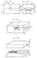
- Figs. 1(a), (b), (c), and (d) show one embodiment of a thermally fused integral ferrule according to this invention showing its basic structure.
- Fig. 1(a) is a schematic front view
- Fig. 1(b) is a right side view
- Fig. 1(c) is a perspective view
- Fig. 1(d) is an exploded perspective view.
- a thermally fused integral ferrule 1 is obtained by using thermal fusion to unitarily combine a first glass substrate 5 having a covered- optical-fiber fixing groove 13a and optical-fiber fixing V-shaped grooves 9 with a second glass substrate 7 having a covered-optical-fiber fixing groove 13b that is complementary with the covered-optical-fiber fixing groove 13a in the first glass substrate 5 and a void 16 that constitutes an optical-fiber guide section (a guide section) 12 with part of the optical-fiber fixing V-shaped grooves 9 in the first glass substrate 5.
- This configuration allows the thermally fused interface 8 between the first and second glass substrates 5 and 7 to have a larger area to improve reliability because the surface of the first glass substrate 5 excluding the covered-optical-fiber fixing grooves 13a, 13b and the void 16 and the whole surface of the second glass substrate 7 are surfaces to be thermally fused.
- optical fibers can be inserted more appropriately, and damages such as disconnection of the optical fibers at the edge of each optical-fiber fixing V-shaped groove 9 can be reduced or avoided.
- the covered-optical-fiber fixing grooves 13a and 13b form a covered-optical-fiber housing section 15, the optical fibers can be inserted straight into the optical-fiber fixing V-shaped grooves 9, while a covered optical fiber can be reliably fixed to the ferrule.
- a thermally fused integral ferrule which is shown in Figs. 3(a), (b), and (c) and 4 (a), (b),and (c), is preferable.
- Figs. 3(a), (b), and (c) show another embodiment of a thermally fused integral ferrule according to this invention.
- Fig. 3(a) is a perspective view
- Fig. 3(b) is an exploded perspective view
- Fig. 3(c) is an explanatory sectional drawing showing that optical fibers are inserted into the ferrule (a fiber array).
- a thermally fused integral ferrule 20 is obtained by using thermal fusion to unitarily combine a first glass substrate 5 having a covered-optical-fiber support section 14 and optical-fiber fixing V-shaped grooves 9 with a second glass substrate 7 having an open portion 17 that constitutes an optical-fiber guide section (a guide section) 12 with part of the optical-fiber fixing V-shaped grooves 9 in the first glass substrate 5.
- the thermally fused interface 8 between the first and second glass substrates 5 and 7 can be minimized to improve the dimensional accuracy of the optical-fiber fixing V-shaped grooves 9.
- the first glass substrate 5 can be simply formed by means of grinding and can simplify the structure of the ferrule to reduce costs.
- Figs. 4(a), (b), and (c) show yet another embodiment of a thermally fused integral ferrule according to this invention.
- Fig. 4(a) is a perspective view
- Fig. 4(b) is an exploded perspective view
- Fig. 4(c) is an explanatory sectional drawing showing that optical fibers are inserted into the ferrule (a fiber array).
- a thermally fused integral ferrule 22 is obtained by using thermal fusion to unitarily combine a first glass substrate 5 having a covered-optical-fiber support section 14 and optical-fiber fixing V-shaped grooves 9 with a second glass substrate 7 having a covered-optical-fiber fixing groove 13b located above the covered-optical-fiber support section 14 and a void 16 that constitutes an optical-fiber guide section (a guide section) 12 with part of the optical-fiber fixing V-shaped grooves 9 in the first glass substrate 5.
- the thermally fused interface 8 between the first and second glass substrates 5 and 7 can be minimized to prevent the V-shaped groove site of the glass substrate 5 accurately formed from being thermally deformed, thereby maintaining the dimensional accuracy of the optical-fiber fixing grooves 9 at the same value as that measured prior to thermal fusion.
- the covered-optical-fiber support section 14 and the covered-optical fiber fixing groove 13b form a covered-optical-fiber housing section 15.
- the optical fibers 2 can be inserted straight into the optical-fiber fixing V-shaped grooves 9 to reliably fix the covered optical fiber 4 to the ferrule 22.
- this embodiment does not require the covered-optical-fiber housing section 15 to be supersonically processed as in the thermally fused integral ferrule shown in Figs. 1(a), (b), (c), and (d).
- the first glass substrate 5 has a stepped structure that can be formed by means of grinding
- the second glass substrate 7 has no V-shaped grooves and can be formed easily by means of press molding.
- the structure of the thermally fused integral ferrule according to this invention is mainly characterized in that the optical-fiber fixing grooves are formed of the V-shaped grooves 9 and in that the optical-fiber guide section 12 is provided in part of the optical-fiber fixing V-shaped grooves 9 (the part in front of the optical-fiber insertion holes 3).
- the optical-fiber fixing grooves are formed of the V-shaped grooves 9 (the optical-fiber insertion holes 3 are shaped like triangles), so the angle of the V-shaped groove 9 can be adjusted to set the opening width of the groove large enough to allow one groove to contact the adjacent one, as shown in Fig. 5(a).
- This configuration enables the optical fibers to be inserted more appropriately.
- optical-fiber insertion holes are circular, semicircular grooves must be formed in each of the first and second glass substrates and must be aligned accurately. It is very difficult to set a precise clearance for the holes and to achieve alignment without deviating from this clearance.
- the optical-fiber fixing V-shaped grooves 9 shown in Fig. 5(a) finally constitute the optical-fiber guide section 12 together with the optical-fiber insertion holes 3 in the thermally fused integral ferrule according to this invention, and are formed in the surface of the first glass substrate 5 by means of grinding.
- the optical-fiber fixing grooves are preferably V-shaped (zigzag) 9.
- pitch (b) that is as long as groove (a) can be provided that has been difficult to achieve with grooves of different shapes such as circular holes.
- This configuration also can prevent the decrease in the strength of the wall surfaces of the V-shaped grooves 9 and the deformation of the V-shaped grooves 9 or damage thereto caused by the thermal fusion of the glass substrates (5 and 7), thereby maintaining the arrangement accuracy and reliability of the optical-fiber fixing V-shaped grooves 9.
- this embodiment does not require precise working for semicircular guide grooves or conical taper used to insert optical fibers as in the conventional MT connector shown in Fig. 7, thereby reducing costs and improving generality.
- the maximum surface roughness (Rmax) of the internal surfaces of the first and second glass substrates 5 and 7 that receive a covered optical fiber and optical fibers is preferably between 0.2 and 2.0 ⁇ m.
- the maximum surface roughness (Rmax) is less than 0.2 ⁇ m, the adhesion strength prior to adhesion cannot be sufficiently maintained. If the maximum surface roughness (Rmax) exceeds 2.0 ⁇ m, the optical fibers are not only likely to be damaged but it is also difficult to maintain the dimensional accuracy.
- the internal surfaces of the first and second glass substrates 5 and 7 that receive a covered optical fiber and optical fibers refer to the internal wall surfaces of the covered-optical-fiber housing section and optical-fiber insertion holes.
- the second glass substrate 7 is placed on the first glass substrate 5 in such a way as to contact it.
- a load of a predetermined value or higher is applied to the interface between the first and second glass substrates 5 and 7.
- the substrates are heated between (Tg1-100) and (Tg2+150) (where Tg1 is the glass transition temperature of one of the first and second glass substrates 5 and 7 that is higher than that of the other and Tg2 is the lower glass transition temperature)°C for a predetermined period of time. Then, the surfaces of the first and second glass substrates 5 and 7 are activated, and this energy causes them to be joined together. Accordingly, the first glass substrate 5 is unitarily combined with the second glass substrate 7 to form a ferrule.
- the fiber fixing V-shaped grooves 9 formed in the first glass substrate 5 are softened and deformed, so holes of a predetermined shape cannot be obtained after cooling.
- the substrates are heated under (Tg1 -100)°C, the activation of the first and second glass substrates 5 and 7 does not start, so fusion is impossible.
- first and second glass substrates 5 and 7 comprise, for example, BK-7
- thermal fusion is effected at 600°C because the glass transition temperature of this material is 557°C.
- second glass substrate 7 comprise Mirachron PC-4 manufactured by NGK Insulators, Ltd.
- thermal fusion can be effected at 530°C because the glass transition temperature of this material is 498°C.
- the first glass substrate 7 is difficult to fuse, whereas the second glass substrate 7 is easy to fuse, resulting in satisfactory fusion. Furthermore, since this temperature is lower than the glass transition temperature of the first glass substrate 5, it serves to restrain the first glass substrate 5 from being thermally deformed, thereby maintaining the geometrical accuracy of the optical-fiber fixing grooves 9 formed in the first glass substrate 5.
- an alternative method may comprise forming a film of a glass frit on the surface to be thermally fused of the first glass substrate 5 in which the optical-fiber fixing V-shaped grooves 9 are formed or on the surface to be thermally fused of the second glass substrate 7, contacting the surfaces to be thermally fused of the substrates together, and thermally fusing the surfaces at the environmental temperature of (Tg3) to (Tg4+150) (where Tg3 is the glass transition temperature of the glass frit and Tg4 is the glass transition temperature of the first glass substrate 5)°C.
- the glass film can be formed by sputtering because the film obtains an even thickness.
- This method enables the first or second glass substrate 5 and 7 to be uniformly and firmly joined together all over the junction interface of the glass frit by means of thermal fusion.
- the glass transition temperature Tg3 of the glass frit lower than that Tg4 of the first glass substrate 5, the glass substrates 5 and 7 can be restrained from thermal deformation caused by thermal fusion, thereby improving the dimensional accuracy and reliability of a completed integral ferrule.
- a glass frit is sputtered onto the surface to be thermally fused of the first or second glass substrate 5 or 7 to form a film of 0.5 ⁇ m thickness and if the first and second glass substrates 5 and 7 comprise BK-7, 7570 (glass transition temperature: 350°C) manufactured by CORNING INCORPORATED that exhibits thermal expansion similar to that of BK-7 and that has a low glass transition temperature can be used to restrain the thermal deformation of the glass substrates 5 and 7 caused by thermal fusion.
- either an oxidization or a reduction atmosphere can be used as a heating atmosphere for the fusion of the glass substrates 5 and 7, the heating time is determined as required depending on the material of the substrates, the heating temperature, and the load.
- the arrangement accuracy is desirably 1 ⁇ m or less. To maintain this accuracy, it is important to strictly control deformation caused by thermal fusion and the dimensional accuracy of the optical-fiber fixing V-shaped grooves prior to fusion.
- the maximum surface roughness (Rmax) of the surface to be thermally fused of each of the first and second glass substrates 5 and 7 is preferably set at 0.5 ⁇ m or less because such roughness reduces the amount of displacement during thermal fusion.
- the amount of displacement depends on the environment temperature, the load, the time required for junction, and the surface roughness of the first and second glass substrates.
- the thermally fused integral ferrule according to this invention does not require the entire contact portion between the first and second glass substrates 5 and 7 to be thermally fused.
- the thermally diffused area is preferably minimized unless the junction strength or watertightness is adversely affected because this minimization enables the dimensions to be controlled easily and also enables the dimensional accuracy of the optical-fiber fixing V-shaped grooves 9 to be maintained. That is, reliability can be maintained if the area of the thermally fused interface between the first and second glass substrates 5 and 7 is 0.01 mm 2 or more in total.
- the tips of optical fibers 2 are arranged over the guide section 12 on the optical-fiber fixing V-shaped grooves 9 in the thermally fused integral ferrule 22 (step (a)), and the tips of the optical fibers 2 are lowered onto the optical-fiber fixing V-shaped grooves 9 (step (b)).
- the optical fibers 2 and the covered optical fibers 4 are inserted into the thermally fused integral ferrule 22 (the covered optical fiber housing section 15) while the optical-fiber fixing V-shaped grooves 9 is being allowed to guide the tips of the fibers 2 (step (c)).
- step (d) a sufficient amount of a first liquid adhesive is applied to and filled in the entire thermally fused integral ferrule 22 into which the optical fibers 2 and the covered-optical fiber 4 has been inserted.
- step (e) the first liquid adhesive was solidified (step (e)) to manufacture a fiber array.
- step (e) If a fiber array is manufactured that uses a thermally fused integral ferrule wherein the second glass substrate 7 is configured in such a way that there is an open space over the guide section 12 on the optical-fiber fixing V-shaped grooves 9 in the first glass substrate 5 while only the optical-fiber fixing V-shaped grooves 9 are covered, then after step (e), it is necessary to cover the guide section 12 and the covered optical fiber 4 with a second liquid adhesive 19 (step (f)) and to solidify the second liquid adhesive (step (g)).
- the first and second liquid adhesives may be of the same type or different types.
- the first liquid adhesive may be applied beforehand to the optical-fiber fixing V-shaped grooves 9 in the first glass substrate 5 or to the optical fibers 2.
- V-shaped grooves are formed in a 50-mm-square glass (BK-7) wafer for 7 groups of fibers each including 16 fibers (112 fibers in total).
- the V-shaped grooves may be formed by means of grinding or pressing.
- the covered-optical-fiber fixing groove constituting the covered-optical-fiber housing section of the thermally fused integral ferrule, or the covered-optical-fiber support section that was a step portion was formed.
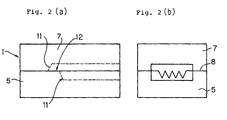
- the covered-optical-fiber fixing groove (Figs. 1(a), (b), (c), and (d) and 2(a) and (b)) was supersonically formed, or the covered-optical-fiber support section (Figs. 3(a), (b), and (c) and 4(a), (b), and (c)) was formed by means of grinding.
- the first glass substrate was obtained.
- the covered-optical-fiber fixing groove (FIGS.1(a), (b), (c), and (d), 2(a) and (b), and 4(a), (b), and (c)) was similarly formed in a 50-mm-square glass (BK-7) wafer by means of pressing.
- the second glass substrate shown in Figs. 3(a), (b), and (c) has no covered-optical-fiber fixing groove and can be formed by simple grinding.
- the second glass substrate was contacted with the first glass substrate, and a load of a predetermined value or higher was applied to the interface between the first and second glass substrates while interface was thermally fused at 600°C because the glass transition temperature of BK-7 is 557°C.
- the glass frit comprised 7570 (glass transition temperature: about 350°C) manufactured by CORNING INCORPORATED that exhibits thermal expansion similar to that of BK-7 and that has a lower melting point than BK-7.
- the tips of the optical fibers were inserted into the guide section on the optical-fiber fixing V-shaped groove in the thermally fused integral ferrule. Then, the optical fibers and the covered-optical-fiber were inserted into the thermally fused integral ferrule while the tips of the optical fibers were being moved along the optical-fiber fixing V-shaped grooves. Next, a sufficient amount of the first liquid adhesive was filled in the gap in the thermally fused integral ferrule for solidification, with the optical fibers and the covered optical fibers already inserted into the ferrule. Finally, the end surface was optically polished to complete a fiber array.
- the alignment effect can be reliably provided to reduce the possibility that the optical fiber may be damaged by the edge of the V-shaped groove.
- this invention provides an inexpensive ferrule that has high junction strength, watertightness, and productivity, and its manufacturing method, as well as a fiber array manufacturing method.
Landscapes
- Physics & Mathematics (AREA)
- General Physics & Mathematics (AREA)
- Optics & Photonics (AREA)
- Mechanical Coupling Of Light Guides (AREA)
Applications Claiming Priority (4)
| Application Number | Priority Date | Filing Date | Title |
|---|---|---|---|
| JP36138597 | 1997-12-26 | ||
| JP36138597 | 1997-12-26 | ||
| JP10360445A JPH11242128A (ja) | 1997-12-26 | 1998-12-18 | 熱融着一体型フェルールとその製造方法、ファイバーアレイの製造方法 |
| JP36044598 | 1998-12-18 |
Publications (2)
| Publication Number | Publication Date |
|---|---|
| EP0926522A2 true EP0926522A2 (de) | 1999-06-30 |
| EP0926522A3 EP0926522A3 (de) | 2002-05-22 |
Family
ID=26581113
Family Applications (1)
| Application Number | Title | Priority Date | Filing Date |
|---|---|---|---|
| EP98310762A Withdrawn EP0926522A3 (de) | 1997-12-26 | 1998-12-24 | Thermisch geschweisster integraler Steckerstift und sein Herstellungsverfahren , und Herstellungsverfahren für ein Faser-Array |
Country Status (3)
| Country | Link |
|---|---|
| US (1) | US6519406B1 (de) |
| EP (1) | EP0926522A3 (de) |
| JP (1) | JPH11242128A (de) |
Cited By (5)
| Publication number | Priority date | Publication date | Assignee | Title |
|---|---|---|---|---|
| EP0947866A3 (de) * | 1998-03-31 | 2002-05-22 | Ngk Insulators, Ltd. | Glassubstrat und zwei Stuffen Giessverfahren |
| EP1003057A3 (de) * | 1998-11-19 | 2002-12-04 | Ngk Insulators, Ltd. | Optischer Faserträger |
| WO2003012511A1 (de) * | 2001-08-01 | 2003-02-13 | Infineon Technologies Ag | Optische kopplungseinheit und verfahren zum einfädeln von lichtwellenleitern in eine optische kopplungseinheit |
| US7445832B2 (en) | 2000-12-25 | 2008-11-04 | Ngk Insulators, Ltd. | Ribboned polarization-maintaining fiber and manufacturing method therefor, and polarization-maintaining optical fiber array using the same |
| EP3534195A4 (de) * | 2016-10-27 | 2020-06-17 | Senko Advanced Components (Hong Kong) Limited | Glasfaseranordnung mit hoher zuverlässigkeit |
Families Citing this family (12)
| Publication number | Priority date | Publication date | Assignee | Title |
|---|---|---|---|---|
| JP3824541B2 (ja) * | 2001-02-27 | 2006-09-20 | 日本碍子株式会社 | 光部品表面実装用基板及びその製造方法、並びにこれを用いた組立品 |
| WO2002079831A1 (en) * | 2001-03-29 | 2002-10-10 | Ngk Insulators,Ltd. | Optical fiber array and method of manufacturing the optical fiber array |
| JP4074563B2 (ja) * | 2003-07-04 | 2008-04-09 | 日本電信電話株式会社 | 光ファイバガイド部品の作製方法 |
| JP2005284157A (ja) * | 2004-03-30 | 2005-10-13 | Ibiden Co Ltd | 光ファイバアレイ |
| JP2007171676A (ja) * | 2005-12-22 | 2007-07-05 | Topcon Corp | 光ファイバケーブル |
| US9528893B2 (en) * | 2009-06-29 | 2016-12-27 | University Of Massachusetts | Optical fiber pressure sensor with uniform diaphragm and method of fabricating same |
| CN102692683A (zh) * | 2011-03-25 | 2012-09-26 | 上海坤腾光电科技有限公司 | 一种光纤阵列定位组件 |
| CN107153238A (zh) * | 2016-03-03 | 2017-09-12 | 扇港元器件(香港)有限公司 | 用于放置和保护光纤拼接点的盒子 |
| US9851509B2 (en) * | 2016-03-31 | 2017-12-26 | Cisco Technology, Inc. | Passive alignment with optical fibers using ferrule member |
| JP7532975B2 (ja) * | 2020-07-17 | 2024-08-14 | 住友電気工業株式会社 | 多心コネクタの製造方法及び多心コネクタ |
| US11899245B2 (en) * | 2021-07-26 | 2024-02-13 | Te Connectivity Solutions Gmbh | Optical receptacle connector for an optical communication system |
| US11906801B2 (en) * | 2021-07-26 | 2024-02-20 | Te Connectivity Solutions Gmbh | Optical receptacle connector for an optical communication system |
Family Cites Families (11)
| Publication number | Priority date | Publication date | Assignee | Title |
|---|---|---|---|---|
| US4830456A (en) | 1986-11-15 | 1989-05-16 | Sumitomo Electric Industries, Ltd. | Optical connector and process for producing the same |
| US4900118A (en) * | 1987-05-22 | 1990-02-13 | Furukawa Electric Co., Ltd. | Multiple-fiber optical component and method for manufacturing of the same |
| US5377289A (en) | 1989-08-02 | 1994-12-27 | E. I. Du Pont De Nemours And Company | Optical fiber connector having an apparatus for positioning the center of an optical fiber along a predetermined reference axis |
| US5379360A (en) | 1992-06-03 | 1995-01-03 | Ngk Insulators, Ltd. | Optical fiber connector and method of manufacturing the same |
| JP3160407B2 (ja) | 1993-02-12 | 2001-04-25 | 日本碍子株式会社 | 光ファイバの接続方法 |
| EP0631162B1 (de) | 1993-06-25 | 1998-09-09 | AT&T Corp. | Befestigungsverfahren für Glasfasern |
| US5528719A (en) | 1993-10-26 | 1996-06-18 | Sumitomo Metal Mining Company Limited | Optical fiber guide structure and method of fabricating same |
| US5500917A (en) | 1994-04-18 | 1996-03-19 | Gould Electronics Inc. | Optical assembly/housing for securing optical fiber components, devices and fibers to the same or to mounting fixtures |
| WO1996000996A1 (en) * | 1994-06-30 | 1996-01-11 | The Whitaker Corporation | Planar hybrid optical amplifier |
| JP3492767B2 (ja) * | 1994-06-30 | 2004-02-03 | 京セラ株式会社 | 光ファイバ位置決め部材とそれを用いた光ファイバの位置決め固定方法 |
| JPH10197761A (ja) * | 1997-01-09 | 1998-07-31 | Ngk Insulators Ltd | 熱融着一体型フェルールおよびその製造方法 |
-
1998
- 1998-12-18 JP JP10360445A patent/JPH11242128A/ja not_active Withdrawn
- 1998-12-21 US US09/217,507 patent/US6519406B1/en not_active Expired - Lifetime
- 1998-12-24 EP EP98310762A patent/EP0926522A3/de not_active Withdrawn
Cited By (6)
| Publication number | Priority date | Publication date | Assignee | Title |
|---|---|---|---|---|
| EP0947866A3 (de) * | 1998-03-31 | 2002-05-22 | Ngk Insulators, Ltd. | Glassubstrat und zwei Stuffen Giessverfahren |
| EP1003057A3 (de) * | 1998-11-19 | 2002-12-04 | Ngk Insulators, Ltd. | Optischer Faserträger |
| US7445832B2 (en) | 2000-12-25 | 2008-11-04 | Ngk Insulators, Ltd. | Ribboned polarization-maintaining fiber and manufacturing method therefor, and polarization-maintaining optical fiber array using the same |
| WO2003012511A1 (de) * | 2001-08-01 | 2003-02-13 | Infineon Technologies Ag | Optische kopplungseinheit und verfahren zum einfädeln von lichtwellenleitern in eine optische kopplungseinheit |
| US6939057B2 (en) | 2001-08-01 | 2005-09-06 | Infineon Technologies Ag | Optical coupling unit and method for inserting optical wave guides into an optical coupling unit |
| EP3534195A4 (de) * | 2016-10-27 | 2020-06-17 | Senko Advanced Components (Hong Kong) Limited | Glasfaseranordnung mit hoher zuverlässigkeit |
Also Published As
| Publication number | Publication date |
|---|---|
| US6519406B1 (en) | 2003-02-11 |
| EP0926522A3 (de) | 2002-05-22 |
| JPH11242128A (ja) | 1999-09-07 |
Similar Documents
| Publication | Publication Date | Title |
|---|---|---|
| US6519406B1 (en) | Thermally fused integral ferrule and its manufacturing method, and fiber array manufacturing method | |
| EP1664871B1 (de) | Optische hülse | |
| US6409394B1 (en) | Optical connector | |
| EP0644442B1 (de) | Endstück einer optischen faser, verfahren zu seiner herstellung und struktur zum verbinden des endstücks mit einer optischen vorrichtung | |
| EP0283301B1 (de) | Verbindung von optischen Fasern | |
| US5613024A (en) | Alignment of optical fiber arrays to optical integrated circuits | |
| US4979970A (en) | Method of manufacturing integrated optical component | |
| CA1305343C (en) | Integrated optical component and method of manufacture | |
| US6103344A (en) | Heat-fused unitary ferrule and method for producing the same | |
| EP0926520B1 (de) | Optisches Faser-Array | |
| JPH11174274A (ja) | 光ファイバアレイおよび金型の製造方法 | |
| US6257770B1 (en) | Optical connector and method of manufacturing the same | |
| EP0694796A1 (de) | Verfahren zur Befestigung eines Glasfaser-Arrays auf einem Substrat | |
| US20030142922A1 (en) | Passive alignment of fiber optic array | |
| WO2002079831A1 (en) | Optical fiber array and method of manufacturing the optical fiber array | |
| JPH10206697A (ja) | 光ファイバ保持部品および光ファイバアレイ | |
| JPH11326678A (ja) | 光ファイバアレイの製造方法 | |
| JP3410672B2 (ja) | 光コネクタおよびその製造方法 | |
| JPH11211928A (ja) | 光ファイバコネクタ | |
| CN221303618U (zh) | 一种光纤阵列和硅光模块 | |
| EP1098213A1 (de) | Verfahren zur Herstellung von Faserschwanz-arrays | |
| JPH11258459A (ja) | 光ファイバコネクタ | |
| JPH06308352A (ja) | 光ファイバアレイフェルール | |
| GB2385678A (en) | Mthod of joining optical components using adhesive | |
| JPH10311924A (ja) | 光ファイバ整列具 |
Legal Events
| Date | Code | Title | Description |
|---|---|---|---|
| PUAI | Public reference made under article 153(3) epc to a published international application that has entered the european phase |
Free format text: ORIGINAL CODE: 0009012 |
|
| AK | Designated contracting states |
Kind code of ref document: A2 Designated state(s): AT BE CH CY DE DK ES FI FR GB GR IE IT LI LU MC NL PT SE |
|
| AX | Request for extension of the european patent |
Free format text: AL;LT;LV;MK;RO;SI |
|
| PUAL | Search report despatched |
Free format text: ORIGINAL CODE: 0009013 |
|
| AX | Request for extension of the european patent |
Free format text: AL;LT;LV;MK;RO;SI |
|
| AKX | Designation fees paid |
Designated state(s): DE FR GB IT |
|
| STAA | Information on the status of an ep patent application or granted ep patent |
Free format text: STATUS: THE APPLICATION IS DEEMED TO BE WITHDRAWN |
|
| 18D | Application deemed to be withdrawn |
Effective date: 20021123 |