EP0925992B1 - Commande de chaîne cinématique pour moteur et transmission à variation continue - Google Patents
Commande de chaîne cinématique pour moteur et transmission à variation continue Download PDFInfo
- Publication number
- EP0925992B1 EP0925992B1 EP98124086A EP98124086A EP0925992B1 EP 0925992 B1 EP0925992 B1 EP 0925992B1 EP 98124086 A EP98124086 A EP 98124086A EP 98124086 A EP98124086 A EP 98124086A EP 0925992 B1 EP0925992 B1 EP 0925992B1
- Authority
- EP
- European Patent Office
- Prior art keywords
- ratio
- drive train
- cvt
- control system
- target
- Prior art date
- Legal status (The legal status is an assumption and is not a legal conclusion. Google has not performed a legal analysis and makes no representation as to the accuracy of the status listed.)
- Expired - Lifetime
Links
- 238000012546 transfer Methods 0.000 claims description 27
- 230000008859 change Effects 0.000 claims description 26
- 238000012937 correction Methods 0.000 claims description 26
- 230000004044 response Effects 0.000 claims description 10
- 238000005070 sampling Methods 0.000 claims description 3
- 238000004590 computer program Methods 0.000 claims 1
- 230000006870 function Effects 0.000 description 32
- 230000005540 biological transmission Effects 0.000 description 17
- 230000001133 acceleration Effects 0.000 description 13
- 238000010586 diagram Methods 0.000 description 13
- 238000002485 combustion reaction Methods 0.000 description 10
- 238000001914 filtration Methods 0.000 description 8
- 230000009467 reduction Effects 0.000 description 8
- 230000007246 mechanism Effects 0.000 description 7
- 230000004048 modification Effects 0.000 description 5
- 238000012986 modification Methods 0.000 description 5
- 230000007935 neutral effect Effects 0.000 description 5
- 230000003466 anti-cipated effect Effects 0.000 description 4
- 230000001276 controlling effect Effects 0.000 description 3
- 230000000994 depressogenic effect Effects 0.000 description 3
- 239000000446 fuel Substances 0.000 description 3
- 238000002347 injection Methods 0.000 description 3
- 239000007924 injection Substances 0.000 description 3
- 238000000034 method Methods 0.000 description 3
- 230000008569 process Effects 0.000 description 3
- 238000006467 substitution reaction Methods 0.000 description 3
- 230000001934 delay Effects 0.000 description 2
- 230000006866 deterioration Effects 0.000 description 2
- 230000000694 effects Effects 0.000 description 2
- 230000000977 initiatory effect Effects 0.000 description 2
- 238000005259 measurement Methods 0.000 description 2
- 230000010363 phase shift Effects 0.000 description 2
- 230000001105 regulatory effect Effects 0.000 description 2
- 230000001052 transient effect Effects 0.000 description 2
- 230000004075 alteration Effects 0.000 description 1
- 238000013459 approach Methods 0.000 description 1
- 238000004364 calculation method Methods 0.000 description 1
- 238000006243 chemical reaction Methods 0.000 description 1
- 230000006835 compression Effects 0.000 description 1
- 238000007906 compression Methods 0.000 description 1
- 230000001143 conditioned effect Effects 0.000 description 1
- 238000005516 engineering process Methods 0.000 description 1
- 239000012634 fragment Substances 0.000 description 1
- 230000002706 hydrostatic effect Effects 0.000 description 1
- 230000002093 peripheral effect Effects 0.000 description 1
- 238000012545 processing Methods 0.000 description 1
- 238000004088 simulation Methods 0.000 description 1
- 238000012360 testing method Methods 0.000 description 1
Images


Classifications
-
- B—PERFORMING OPERATIONS; TRANSPORTING
- B60—VEHICLES IN GENERAL
- B60W—CONJOINT CONTROL OF VEHICLE SUB-UNITS OF DIFFERENT TYPE OR DIFFERENT FUNCTION; CONTROL SYSTEMS SPECIALLY ADAPTED FOR HYBRID VEHICLES; ROAD VEHICLE DRIVE CONTROL SYSTEMS FOR PURPOSES NOT RELATED TO THE CONTROL OF A PARTICULAR SUB-UNIT
- B60W10/00—Conjoint control of vehicle sub-units of different type or different function
- B60W10/04—Conjoint control of vehicle sub-units of different type or different function including control of propulsion units
- B60W10/06—Conjoint control of vehicle sub-units of different type or different function including control of propulsion units including control of combustion engines
-
- B—PERFORMING OPERATIONS; TRANSPORTING
- B60—VEHICLES IN GENERAL
- B60W—CONJOINT CONTROL OF VEHICLE SUB-UNITS OF DIFFERENT TYPE OR DIFFERENT FUNCTION; CONTROL SYSTEMS SPECIALLY ADAPTED FOR HYBRID VEHICLES; ROAD VEHICLE DRIVE CONTROL SYSTEMS FOR PURPOSES NOT RELATED TO THE CONTROL OF A PARTICULAR SUB-UNIT
- B60W10/00—Conjoint control of vehicle sub-units of different type or different function
- B60W10/04—Conjoint control of vehicle sub-units of different type or different function including control of propulsion units
-
- B—PERFORMING OPERATIONS; TRANSPORTING
- B60—VEHICLES IN GENERAL
- B60W—CONJOINT CONTROL OF VEHICLE SUB-UNITS OF DIFFERENT TYPE OR DIFFERENT FUNCTION; CONTROL SYSTEMS SPECIALLY ADAPTED FOR HYBRID VEHICLES; ROAD VEHICLE DRIVE CONTROL SYSTEMS FOR PURPOSES NOT RELATED TO THE CONTROL OF A PARTICULAR SUB-UNIT
- B60W10/00—Conjoint control of vehicle sub-units of different type or different function
- B60W10/10—Conjoint control of vehicle sub-units of different type or different function including control of change-speed gearings
- B60W10/101—Infinitely variable gearings
- B60W10/108—Friction gearings
- B60W10/109—Friction gearings of the toroïd type
-
- B—PERFORMING OPERATIONS; TRANSPORTING
- B60—VEHICLES IN GENERAL
- B60W—CONJOINT CONTROL OF VEHICLE SUB-UNITS OF DIFFERENT TYPE OR DIFFERENT FUNCTION; CONTROL SYSTEMS SPECIALLY ADAPTED FOR HYBRID VEHICLES; ROAD VEHICLE DRIVE CONTROL SYSTEMS FOR PURPOSES NOT RELATED TO THE CONTROL OF A PARTICULAR SUB-UNIT
- B60W30/00—Purposes of road vehicle drive control systems not related to the control of a particular sub-unit, e.g. of systems using conjoint control of vehicle sub-units
- B60W30/18—Propelling the vehicle
- B60W30/1819—Propulsion control with control means using analogue circuits, relays or mechanical links
-
- F—MECHANICAL ENGINEERING; LIGHTING; HEATING; WEAPONS; BLASTING
- F16—ENGINEERING ELEMENTS AND UNITS; GENERAL MEASURES FOR PRODUCING AND MAINTAINING EFFECTIVE FUNCTIONING OF MACHINES OR INSTALLATIONS; THERMAL INSULATION IN GENERAL
- F16H—GEARING
- F16H61/00—Control functions within control units of change-speed- or reversing-gearings for conveying rotary motion ; Control of exclusively fluid gearing, friction gearing, gearings with endless flexible members or other particular types of gearing
- F16H61/66—Control functions within control units of change-speed- or reversing-gearings for conveying rotary motion ; Control of exclusively fluid gearing, friction gearing, gearings with endless flexible members or other particular types of gearing specially adapted for continuously variable gearings
-
- B—PERFORMING OPERATIONS; TRANSPORTING
- B60—VEHICLES IN GENERAL
- B60L—PROPULSION OF ELECTRICALLY-PROPELLED VEHICLES; SUPPLYING ELECTRIC POWER FOR AUXILIARY EQUIPMENT OF ELECTRICALLY-PROPELLED VEHICLES; ELECTRODYNAMIC BRAKE SYSTEMS FOR VEHICLES IN GENERAL; MAGNETIC SUSPENSION OR LEVITATION FOR VEHICLES; MONITORING OPERATING VARIABLES OF ELECTRICALLY-PROPELLED VEHICLES; ELECTRIC SAFETY DEVICES FOR ELECTRICALLY-PROPELLED VEHICLES
- B60L2240/00—Control parameters of input or output; Target parameters
- B60L2240/40—Drive Train control parameters
- B60L2240/48—Drive Train control parameters related to transmissions
- B60L2240/486—Operating parameters
-
- B—PERFORMING OPERATIONS; TRANSPORTING
- B60—VEHICLES IN GENERAL
- B60W—CONJOINT CONTROL OF VEHICLE SUB-UNITS OF DIFFERENT TYPE OR DIFFERENT FUNCTION; CONTROL SYSTEMS SPECIALLY ADAPTED FOR HYBRID VEHICLES; ROAD VEHICLE DRIVE CONTROL SYSTEMS FOR PURPOSES NOT RELATED TO THE CONTROL OF A PARTICULAR SUB-UNIT
- B60W2510/00—Input parameters relating to a particular sub-units
- B60W2510/10—Change speed gearings
- B60W2510/1005—Transmission ratio engaged
-
- B—PERFORMING OPERATIONS; TRANSPORTING
- B60—VEHICLES IN GENERAL
- B60W—CONJOINT CONTROL OF VEHICLE SUB-UNITS OF DIFFERENT TYPE OR DIFFERENT FUNCTION; CONTROL SYSTEMS SPECIALLY ADAPTED FOR HYBRID VEHICLES; ROAD VEHICLE DRIVE CONTROL SYSTEMS FOR PURPOSES NOT RELATED TO THE CONTROL OF A PARTICULAR SUB-UNIT
- B60W2540/00—Input parameters relating to occupants
- B60W2540/10—Accelerator pedal position
-
- B—PERFORMING OPERATIONS; TRANSPORTING
- B60—VEHICLES IN GENERAL
- B60W—CONJOINT CONTROL OF VEHICLE SUB-UNITS OF DIFFERENT TYPE OR DIFFERENT FUNCTION; CONTROL SYSTEMS SPECIALLY ADAPTED FOR HYBRID VEHICLES; ROAD VEHICLE DRIVE CONTROL SYSTEMS FOR PURPOSES NOT RELATED TO THE CONTROL OF A PARTICULAR SUB-UNIT
- B60W2710/00—Output or target parameters relating to a particular sub-units
- B60W2710/06—Combustion engines, Gas turbines
- B60W2710/0677—Engine power
Definitions
- the present invention relates to a drive train control system having the features contained in the preamble portion of claim 1. Such a system is disclosed in EP 0 530 381 A1.
- engine is herein used to mean an internal combustion engine, an electric motor and a hybrid power unit that includes an internal combustion engine and an electric motor.
- This known CVT control system adjusts CVT ratio rate in response to an output speed of CVT in such a manner as to restrain inertia torque from exceeding a predetermined value.
- JP-A 8-177541 discloses an engine torque control system for an engine-CVT drive train.
- a ratio rate due to the downshift is anticipated and a drop, in amount, of engine torque is anticipated based on the anticipated ratio rate.
- the engine Ignition timing is retarded in accordance with the anticipated drop of engine torque for a reduction of the engine torque.
- the amount of the ignition timing retard is gradually reduced in accordance with the actual CVT ratio rate. This control is intended to provide smooth increase in engine torque upon acceleration.
- the known CVT ratio rate control system may not sufficiently meet driver's acceleration demand because drop in CVT ratio rate to suppress inertia torque causes slow acceleration during CVT ratio change in downshift direction.
- Variations of the speeds of input and output shafts of CVT are measured for calculation of CVT ratio. These measured values of the speeds may involve measurement errors and noises that are not predictable and difficult to remove by the present technology. Deviations of calculated values of the CVT ratio from variations of the CVT ratio are subject to such measurement errors and noises. Unless appropriately processed, the calculated values of the CVT ratio cannot be regarded as G in the equation (1). If these values are substituted for G, calculated values of dG/dt are greatly deviated from variations of dG/dt, causing great deviations of calculated values of T I from variations of T I . Thus, using the calculated values of T I in altering engine torque will fail to meet driver's acceleration demand during downshift for acceleration.
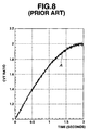
- Figures 8 to 13 show simulation results.
- the reference character A shows plotting of simulated measures resulting from superimposing random noise with the probability density of the normal distribution, where variance is 0.01, upon real variations of CVT ratio from 1 to 2 against time over period of 2 seconds.
- a curve B connects values resulting from repeating subtraction of a previously sampled old value of the real variations of CVT ratio from a currently sampled new value thereof over 0 to 2 seconds.
- the reference character C shows plotting of values resulting from repeating subtraction of a previously sampled old value of the measures in Figure 8 from a currently sampled new value thereof over 0 to 2 seconds.
- the values shown in Figures 9(A) may be regarded as dG/dt, where the real variations are substituted for G in equation (1).
- the values shown in Figure 9(B) may be regarded as dG/dt, where the simulated measures shown in Figure 8 are substituted for G in equation (1). Comparing Figure 9(B) with Figure 9(A) reveals that the values of Figure 9(a) deviates from the corresponding values of Figure 9(B) too much to represent the real variations of dG/dt. This means that values resulting from calculating equation (1) after substitution of the values of Figure 9(B) for dG/dt will fail to represent real variations of the inertia torque ⁇ Te_inertia.
- Filters are often used to process measures for removal or at least reduction of noise component.
- a curve as indicated by the reference character a shows real variations of the CVT ratio from 1 to 2 over a period of 2 seconds, while a curve indicated by the reference character b shows values resulting from filtering the real variations. Comparing the curve b with the curve a clearly shows that the filtering has caused a phase shift.
- the measures of the CVT ratio as shown at A in Figure 8 are subjected to the filtering process to give filtered measures.
- the reference character C1 shows plotting of values resulting from repeating subtraction of a previously sampled old value of the filtered measures from a currently sampled new value thereof over 2 seconds.
- the curve B in Figure 9(A) is drawn in Figure 11 for comparison with the plotting C1. Comparing the plotting C1 in Figure 11 with the plotting C in Figure 9(B) reveals that the noise component has been reduced. However, the values on the plotting C1 shown in Figure 11 still suffer from undesired variations, so that they cannot be used as substitution for dG/dt in the equation (1).
- Figures 12 and 13 illustrate test results from signal processing with another filter, which has a different characteristic.
- a curve a shows real variations of the CVT ratio from 1 to 2 over a period of 2 seconds, while a curve indicated by the reference character b1 shows values resulting from filtering the real variations. Comparing the curve b1 with the curve b shown in Figure 10 clearly shows that this filtering has caused a greater phase shift.
- the measures of the CVT ratio as shown at A in Figure 8 are subjected to the filtering by this another filter to give filtered measures.
- the reference character C2 shows plotting of values resulting from repeating subtraction of a previously sampled old value of the filtered measures from a currently sampled new value thereof over 2 seconds.
- the curve B of Figure 9(A) is drawn in Figure 13 for comparison with the plotting C2. Comparing the plotting C2 in Figure 13 with the plotting C1 in Figure 11 reveals that the noise component has been reduced. However, the deviation from the curve B has increased, so that the values on the plotting C2 cannot be used as substitution for dG/dt in the equation (1).
- US 5,305,662 discloses a control device for an internal combustion engine and a CVT which enables well responsible transmission control.
- An object of the present invention therefore is to improve a control system for a vehicle drive train including an engine and a CVT such that the above-mentioned need is fulfilled.
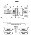
- Figure 1 illustrates an engine-CVT drive train for a passenger automotive vehicle with a manually operable accelerator or gas pedal that has various depressed positions in response to varying operator power demand.
- the drive train indudes an engine 1 and a continuously variable transmission (CVT) 3.
- CVT continuously variable transmission
- the present invention is operational with any type of engine whose torque output can be controlled, including a gasoline engine, a diesel engine, an electric motor, and hybrid power unit.
- the present invention is operational with any type of CVT in which ratio rate can be controlled, including hydrostatic and friction CVTs.
- Examples of the friction CVTs are a V-belt CVT with a V-belt interconnecting an input pulley and an output pulley and a toroidal CVT with friction rollers between and in engagement with a set of coaxial toric input and output discs.
- a torque control element controls the torque output of the engine 1.
- the torque control element is a throttle valve 1a that opens in degrees to regulate intake air, in amount, admitted to the engine.
- the torque control is not limited to regulating the intake air, and regulating fuel injection, in amount, also may be employed to control the engine torque.
- the torque control element may include a fuel injection pulse width modulator.
- the engine 1 outputs its power through the engine output shaft 20.
- the engine output shaft 20 is connected to an input shaft 22 of the CVT 3.
- the CVT 3 transfers the engine power to its CVT output shaft 24.
- the CVT output shaft 24 transfers the engine power to a final drive 4, which moves the vehicle with road wheels 5.
- a clutch may be positioned between the engine output shaft 20 and the CVT input shaft 22 to engage and disengage the road load to the engine 1.
- the dutch needs not to be positioned before the CVT. It may be also positioned between the CVT output shaft 24 and the final drive 4.
- the clutch may be replaced with a hydrodynamic unit such as a torque converter 2a.
- the torque converter 2a may be positioned between the engine output shaft 20 and the CVT input shaft 22.
- the CVT input shaft 22 may be connected to a forward-reverse (F-R) changeover mechanism 2b to change direction of rotation of the road wheels 5.
- the F-R changeover mechanism 2b needs not to be positioned before the CVT 3. It may also be positioned between the CVT output shaft 24 and the final drive 4. All of the above components of the engine-CVT drive train transfer the load of the vehicle back to the engine 1.
- the vehicle operator perceives the state of the vehicle through normal senses.
- the operator depresses or releases the accelerator pedal sending a power request command to an engine-CVT controller 8 through an accelerator sensor 9.
- the accelerator sensor 9 detects depressed position of the accelerator pedal and generates an accelerator (ACC) signal indicative of the detected depressed position.
- the operator sends a select signal (e.g. Park, Drive, Neutral, Reverse) to the engine-CVT controller 8.
- the controller 8 controls the F-R changeover mechanism 2b in response to the select signal.
- the controller 8 senses the state of the engine 1 and the CVT 3 through a vehicle speed sensor 10 and through an engine speed sensor 12.
- the controller 8 also senses the state of the drive train or driveline through wheel speed sensors 11.
- the vehicle speed sensor 10 detects rotational speed of the CVT output shaft 24.
- Each wheel speed sensor 11 generates a train of pulses, as its output signal, which is indicative of wheel rotational speed of the associated road wheel 5.
- the engine speed sensor 12 detects rotational speed of the engine output shaft 20, which is also the speed of the CVT input shaft 22. In the case where the torque converter 2a is positioned between the engine output shaft 20 and the CVT input shaft 22, a table look-up conversion may be needed to compensate for any difference between the engine speed and the CVT input shaft speed, which may occur during transients.
- the engine speed sensor may be replaced with a turbine speed sensor.
- the turbine speed sensor detects rotational speed of a turbine shaft 26 of the torque converter 2a, which is also the speed of the CVT input shaft 22.
- the controller 8 sends a throttle actuator command through a line 28 and a ratio actuator command through a line 30.
- the throttle actuator command controls operation of a throttle actuator 1b, which positions the throttle valve 1a through the actuator shaft represented by dotted line 1c.
- the ratio actuator command controls the ratio of the CVT 3 by controlling a stepping motor, which positions a spool of a servo valve system.
- the stepping motor and the servo valve system are well known and disclosed in US-A 5,083,474 issued to Nakano on Jan. 28, 1992.
- a representative example of controlling the ratio of the CVT is disclosed in US-A 5,707,313 issued to Suzuki on Jan. 13, 1998.
- the controller 8 may include a microcomputer and its peripheral devices and it is designed to perform total management of a vehicle with the drive train illustrated in Figure 1.
- FIG. 2 illustrates the engine 1 used in this embodiment.
- the engine 1 is in the form of a gasoline internal combustion engine.
- the engine 1 has a plurality of cylinders, only one being shown and designated at 100 in Figure 2, in a cylinder block 102 with a cylinder head 104 thereon.
- An intake manifold 106 is connected to an intake path 108 in which the throttle flap 1a is mounted.
- the intake manifold 106 is connected to the cylinder head 104 for admission of intake air to combustion spaces, only one being shown in Figure 2 and designated at 110, of the cylinders.
- a fuel injection or admission system, not shown, is admitted to the combustion spaces to form combustible charge therein,
- An exhaust manifold 112 is connected to the cylinder head 104 for discharge of exhaust gas resulting from combustion within the combustion spaces.
- An exhaust gas recirculation conduit (EGR) 114 provides a path through which a portion of the exhaust gas passes into the intake manifold 106.
- a solenoid operable EGR valve 116 forms a part of an EGR passage in the EGR conduit 114 and has different valve openings.
- the cylinders have pistons, respectively, only one being shown in Figure 2 and designated at 118.
- the cylinder head 104 has cylinder valves including intake valves, only one being shown in Figure 2 and designated at 120, and exhaust valves, only one being shown in Figure 2 and designated at 122, and ignition plugs, only one being shown in Figure 2 and designated at 124.
- Each cylinder performs an intake phase where its piston descends with its intake valve or valves open and a compression phase where its piston ascends.
- a combustion and power phase is initiated by spark by its ignition plug.
- the power phase is followed by an exhaust phase where its piston ascends to displace exhaust gas out of the cylinder via the exhaust valve or valves.
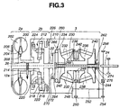
- the torque converter 2a is positioned between the engine output shaft 20 and the CVT input shaft 22 and the F-R changeover mechanism 2b is positioned between the torque converter 2a and the CVT input shaft 22.
- the torque converter 2a includes a pump impeller 200 connected to the engine output shaft 20, a turbine runner 202 connected to turbine shaft 26, and a stator 204 situated between the pump impeller 200 and the turbine runner 202.
- a lockup or bridge clutch 206 is positioned to engage and disengage the turbine runner 202 to the pump impeller 200.
- One-way clutch 208 is positioned to anchor the stator 204 to a transmission casing 210 to prevent the stator 204 from rotating in one direction.
- the speed sensor 12a is arranged around the turbine shaft 26 to detect rotational speed of the turbine shaft 26.
- the F-R changeover mechanism 2b includes a planetary gear set (PGS).
- a sun gear 214 of the PGS is connected to the turbine shaft 26.
- a pinion carrier 216 of the PGS is connected to the CVT input shaft 22.
- the pinion carrier 216 supports a plurality of pairs of intermeshed pinions, namely, an outer pinion 218 and an inner pinion 220.
- the outer pinions 218 are in meshing engagement with a ring gear 222, while the inner pinions 220 are in meshing engagement with the sun gear 214,
- a forward clutch 224 is positioned to engage and disengage the pinion carrier 216 to the turbine shaft 26.
- a reverse brake 226 is positioned to anchor and release the ring gear 222 to the transmission casing 210.
- both the forward clutch 224 and the reverse brake 226 are released to disengage the CVT 3 from the engine.
- the forward clutch 224 is engaged and the reverse brake 226 left released.
- the PGS is locked for allowing unitary rotation of the CVT input shaft 22 with the turbine shaft 26.
- the reverse brake 226 is engaged or applied with the forward clutch 224 left released. Under this condition, as the ring gear 222 is anchored, forward rotation of the sun gear 214 causes reverse rotation of the pinion carrier 216 and the CVT input shaft 22.
- the CVT input shaft 22 is coaxial with a center shaft 230 that is supported by the transmission casing 210.
- First traction rollers 230 are positioned between and in engagement with a first set of toroidal input and output discs 234 and 236.
- Second traction rollers 238 are positioned between and in engagement with a second set of toroidal input and output discs 240 and 242.
- the output discs 236 and 242 of the first and second sets are disposed between the input discs 234 and 240 of the first and second sets.
- the input discs 234 and 240 are connected to the center shaft 230 through the ball spline connections 242 and 244, respectively, for rotation with the center shaft 230 as a unit.
- the transmission casing 210 supports via bearings an output gear 246 for rotation relative thereto.
- the output gear 246 is positioned between the output discs 236 and 242 and has a sleeve extension 248.
- the output discs 236 and 242 are connected to the sleeve extension 248 by spline connections for rotation with the output gear 246.
- the output gear 246 meshes with a first gear 250 of an intermediate shaft 252 that is supported by the transmission casing 210.
- the intermediate shaft extends outwardly of the transmission casing 210.
- a second gear 254 of the intermediate shaft 252 is positioned outside the transmission casing 210 and meshes with a gear 256 of the CVT output shaft 24.
- the turbine speed sensor 12A is arranged to detect rotational speed of the turbine shaft 26.
- a first loading arrangement 260 is positioned to bias the input disc 234 of the first set toward the output disc 236 thereof.
- a second loading arrangement 262 is positioned to bias the input disc 240 of the second set toward the output disc 242 thereof.
- the first loading arrangement 260 includes a cam flange 264 and a cam roller 266.
- the cam flange 264 is supported by the center shaft 230 by a bearing 268 and connected to a radial extension of the CVT input shaft 22 by spline connection for rotation therewith as a unit.
- the cam roller 266 is positioned between and in engagement with opposing cam surfaces of the cam flange 264 and the adjacent input disc 234.
- the second loading arrangement 262 indudes a thrust ball bearing 274 and a Belleville spring 276.
- the Belleville spring 276 is positioned between and in engagement with the input disc 240 of the second set and the thrust ball bearing 274.
- Tiling the rollers 232 and 238 alters a ratio between rotational speed of the input discs 234 and 240 and rotational speed of the output discs 236 and 242.
- the force to tilt the rollers is generated due to "steering" effect that is produced by offsetting the axes of rotation of the rollers from the axis of rotation of the discs. This effect is analogous to the change in vehicle's orientation when the vehicle steering wheel is turned.
- the axes of rotation of the rollers are offset by the servo valve system and the stepping motor, which are disclosed in US-A 5,083,473, in response to the ratio actuator command signal.
- Haruyoshi KUMURA et al. reported on the passenger car performance using the engine-CVT drive train in "Performance of a Dual-Cavity Half-Toroidal CVT for Passenger Cars"pp 135-140 of International Conference on Continuously Variable Power Transmissions held September 11-12, 1996.
- the operator signal from the accelerator pedal on line 300 is used as the input to a power request command generator 302.
- the power request command generator 302 may be as simple as a look-up table in the controller memory.
- the power request command generator 302 outputs a power command signal on line 304,
- the power command signal on line 304 is input into a throttle command generator 306.
- a measure of actual engine speed on line 308 is also input into the throttle command generator 306.
- the throttle command generator 306 generates, as a function of power command and actual engine speed, a throttle position command on line 310.
- the throttle command generator 306 may be a two-dimensional look-up table in the controller memory.
- the throttle position command on line 310 is input into a summation block 312, which corrects the throttle position command with a throttle angle correction on line 314.
- the summation block 312 outputs a corrected throttle position command on line 316.
- the corrected throttle position command on line 316 is input into comparison block 318, which compares the actual throttle position on line 320 with the corrected throttle position command on line 316 and outputs a throttle error signal on line 322.
- the throttle error signal is input into throttle control loop 324, which controls the position of the throttle 1a.
- the throttle control loop 324 may consist of a PID controller, but not limited to such a controller.
- the actual throttle position represented by line 320 controls the torque output of the engine, represented by block 326.
- the operator signal from the accelerator pedal on line 300 is also input into target speed generator 332.
- a measure of actual vehicle speed (VSP) on line 334 is also input into target speed generator 332.
- the target speed generator 332 generates, as a function of the operator signal from the accelerator sensor 9 and actual vehicle speed (VSP), a target CVT input speed signal (Ni) on line 336.
- the target speed generator 332 may be a two-dimensional look-up table in the controller memory. Figure 6 illustrates one example of the relation between data in this two-dimensional table.
- the target CVT input speed (Ni) on line 336 is input into target ratio generator 338.
- the actual vehicle speed on line 334 is also input into target ratio generator 338.
- the target ratio generator 338 computes a target ratio (Gt) as a function of the CVT input speed and the actual vehicle speed and outputs target ratio signal (Gt) line 340.
- the target ratio (Gt) on line 340 is input into ratio command generator 342.
- the ratio command generator 342 outputs ratio command (Gi) on line 344.
- ratio command (Gi) Various manners of determining ratio command (Gi) out of target ratio (Gt) will be later described.
- the ratio command on line 344 is input into speed command generator 346.
- the actual vehicle speed on line 334 is also input into speed command generator 346, which outputs a speed command signal on line 348.
- the speed command generator 346 may be a two-dimensional look-up table in controller memory.
- the speed command on line 348 is input into comparator block 350, which compares the speed command with actual engine speed on line 308 and outputs a speed error signal on line 352.
- the speed error signal on line 352 is input into speed control loop 354.
- the speed control loop 354 may be a simple PID controller but is not so limited.
- the speed control loop 354 outputs stepping motor position command, as the ratio actuator command, on line 356.
- the stepping motor position command is limited by a limit function in bock 358.
- the stepping motor position command is then output on line 360 and controls ratio in the CVT.
- Line 362, leading into block illustrates that ratio rate in the CVT affects the driveline dynamics of the vehicle controlling the
- the ratio command (Gi) on line 344 is also input into inertia torque generator 370.
- the sensor output of the wheel speed sensor 11 on line 372 is used as the input to an angular speed generator 374.
- the angular speed generator 374 may be a counter in the controller 8.
- the angular speed generator 374 outputs a wheel angular speed ( ⁇ w ) on line 376.
- the wheel angular speed ( ⁇ w ) on line 376 is input into the inertia torque generator 370.
- Moment of inertia (J1) on line 378 is used as input to the inertia torque generator 370.
- the moment of inertia (J1) is a predetermined constant.
- a final drive reduction ratio (Gf) on line 380 is used as input to the inertia torque generator 370.
- the final drive ratio (Gf) is a predetermined constant.
- the inertia torque generator 370 generates, as a function of ratio command (Gi), wheel angular speed ( ⁇ w ), moment of inertia (J1) and final drive reduction ratio (Gf), inertia torque ( ⁇ Te_inertia) on line 382.
- the inertia torque ( ⁇ Te_inertia) on line 382 is input into a correction generator 384.
- the measure of actual engine speed on line 308 is also input into the correction generator 384.
- the correction generator 384 may be as simple as a look-up table in the controller memory.
- the correction generator 384 generates a throttle angle correction, which is required to get engine torque change against the inertia torque ( ⁇ Te_inertia), on line 314.
- the throttle angle correction on line 314 is input into the summation block 312.
- ratio command generator 342 target ratio (Gt) on line 340 is used as the input and ratio command (Gi) is generated on the line 344.
- Ratio command (Gi) on line 334 controls ratio rate with respect to time during transient to the target ratio (Gt).
- ⁇ Gi(k-1) is ratio command computed last time
- Gtk is target ratio computed this time
- ⁇ G is a difference between actual ratio measured this time and that measured last time.
- R1(s) is a mathematical expression of a canonical model that represents a desired change in ratio until target ratio Gt is accomplished
- R2(s) is a mathematical expression of an estimated model of a transfer function of the CVT.
- the fourth manner of determining ratio command Gi is to use a filter that represents a canonical model characteristic M(S).
- This filter is a digital filter that is given after converting a canonical model characteristic Gm(s) expressed in continuous-time system into that expressed in discrete-time system.
- the ratio command generator 342 generates ratio command Gi on line 344.
- Ratio command Gi on line 344 is used as the input to speed ratio command generator 346 and also to inertia torque generator 370.
- (dG/dt) C ⁇ G t ( k ) + D ⁇ G t ( k ⁇ 1 ) + E ⁇ ( d G / d t ) ( k ⁇ 1 )
- C ⁇ 1 - exp (-Tsamp/T1) ⁇ /Tsamp
- D ⁇ exp(-Tsamp/T1) - 1 ⁇ Tsamp
- E exp(-Tsamp/T1).
- the third manner of computing time differential of ratio (dG/dt) is to compute time differential (dGt/dt) of the target ratio on line 340.
- the inertia torque generator 370 generates inertia torque ⁇ Te_inertia on line 382.
- the inertia torque ⁇ Te_inertia on line 382 is used as the input to correction generator 384.
- Actual engine speed on line 308 is also used as the input to the correction generator 384.
- the correction generator 384 may be a look-up table that is extracted from engine torque vs., throttle valve angle curves as shown in Figure 7 and stored in controller memory.
- the correction generator 384 generates throttle angle correction, which is required to get engine torque change against the inertia torque ⁇ Te_inertia, on line 314.
- the throttle angle correction on line 314 is input into the summation block 312.
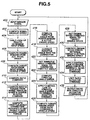
- the flow chart in Figure 5 illustrates a control routine of the preferred implementation of the present invention.
- the controller 8 inputs information of: accelerator pedal angle or position, transmission shift position (Park, Neutral, Drive, Reverse), engine speed, vehicle speed, road wheel speed and throttle position.
- step 402 the controller computes wheel angular speed ( ⁇ w) of road wheels 5.
- step 404 the controller performs a table look-up operation of Figure 6 to determine CVT input speed (Ni).
- step 406 the controller computes power demand from the accelerator pedal angle.
- step 408 the controller computes target ratio (Gt) from input speed (Ni) and vehicle speed (VSP) using the equation Eq. 2.
- step 410 the controller computes ratio command (Gl) from target ratio (Gt) using the equation Eq. 3.
- step 412 the controller computes inertia torque ( ⁇ Te_inertia) from ratio command (Gi).
- step 414 the controller computes throttle angle correction required to get engine torque change against inertia torque ( ⁇ Te_inertia).
- step 416 the controller computers throttle angle from power demand and actual engine speed.
- step 418 the controller corrects the throttle angle with the throttle angle correction.
- step 420 throttle angle command is made equal to the corrected throttle angle.
- step 422 the controller computes throttle angle error from the actual throttle angle and the throttle angle command.
- step 424 the controller uses a control routine to computer a throttle actuator command.
- step 426 the controller computes target engine speed from ratio command (Di) and vehicle speed (VSP).
- step 428 engine speed command is made equal to the target engine speed.
- step 430 the controller computes engine speed error from the actual engine speed and the engine speed command.
- step 432 the controller uses a control routine to compute ratio actuator command.
- step 434 the controller imposes a limit to the ratio actuator command.
- step 436 the throttle actuator command and ratio actuator command are output.
- the above flow chart illustrates just one implementation of the present invention.
- the present invention is not limited to the use of the control routine described above.
- the above description illustrates the benefits of the present invention, including improved control over the transient response of the engine-CVT drive train.
- a target ratio Gt of the target ratio generator 338 is used as an input to the ratio command generator 342 and a ratio command of the ratio command generator 342 is used as an input to the inertia torque generator 370.
- the inertia torque generator 370 thus generates an inertia torque ( ⁇ Te_inertia) on line 382 from or based on a target ratio (Gt) on line 340.
- FIG. 4A is a portion of Figure 4 incorporating such modifications.
- Figure 48 is block diagrams of the target engine torque compensating magnitude generator 370A.
- P(s) represents transfer characteristic from target ratio Gt to actual ratio G
- T CVT is a time constant of delay in CVT
- inertia torque ⁇ Te_inertia J 1 ⁇ ⁇ W ⁇ G f ⁇ s ⁇ P ( s ) ⁇ e T C V T s ⁇ G t
- inertia torque compensating magnitude ⁇ Te_control is computed from target ratio Gt.
- the inertia torque compensating magnitude ⁇ Te_control results from delays in the engine and In electronically controlled throttle.
- Such delays include a time constant T E of an intake air admission delay, an output torque dead time T D , and a time constant T ETC of a throttle delay.
- the intake air admission delay is a delay from a change in throttle angle and a resultant change in admission of intake air into engine cylinder.
- the output torque dead time T D is a dead time between admission of combustible charge and generation of torque resulting from combustion of the intake charge.
- the throttle delay is a delay from a command for a target throttle angle to accomplishment of the target throttle angle.
- the filter Gril0(s) for phase adjustment between the inertia torque ⁇ Te_inertia and the inertia toque compensating magnitude ⁇ Te_control can be extracted from the equations Eq, 12 and Eq.
- G fil 0 ( s ) s ⁇ P ( s ) ⁇ ( T E ⁇ s + 1 ) ( T E T C ⁇ s + 1 ) ⁇ e ⁇ ( T C V T ⁇ T D ) s
- the target engine torque compensating magnitude generator 370A indudes a filter 500 and a function generator 502.
- the Gfil0(s) is computed from the equation Eq. 14 and applied to the function generator 502 along with J1, ⁇ w and Gf.
- Target ratio Gt on line 340 is used as an input to the function generator 502.
- the function generator 502 generates the target engine compensating magnitude ⁇ tTe on line 382A.
- the target engine torque compensating magnitude ⁇ tTe on line 382A is used as an input to a correction generator 384 (see Figure 4A).
- Engine speed Ne on line 308 is used as an input to the correction generator 384.
- a table look-up operation is performed based on combination of Ne and ⁇ tTe to find a throttle angle correction required to get the target engine torque compensating magnitude ⁇ tTe.
- FIG 14 illustrates variations of the time constant T E of intake air admission delay against engine speed Ne and engine load TP.
- Figure 15 illustrates variation of the time constant T D of dead time against engine speed Ne. It is found that the time constant T ETC is unaltered over the entire operating conditions.
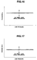
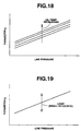
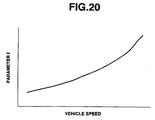
- Figures 16 to 20 illustrate variations in parameters a, b, g and f versus operating conditions.
- the parameters a and b stay unaltered over variations in line pressure, but they alter depending on oil temperature and load.
- the magnitude of alteration of each of the parameters a and b depending upon oil temperature and load is small.
- the parameter g is proportional to line pressure.
- the parameter g increases as oil temperature increases (see Figure 18).
- the parameter g alters depending on engine load, but its magnitude is small (see Figure 19).
- the parameter f increases as vehicle speed increases.
- the CVT dynamics G CVT (s) is given by the equation Eq. 17 and the time constant G LOGIC is given by the programs of the control routine for ratio change. From the above, it is understood that the filter Gfi10(s) can be readily computed without any difficulty.
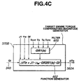
- Figure 4C is substantially the same as Figure 4B except that a target engine torque compensating magnitude generator 370B employs filter Gfil1(s) instead of the filter Gfil0(s) of the generator 370A.
- inertia torque ⁇ Te_inertia J 1 ⁇ ⁇ W ⁇ G f ⁇ s ⁇ Q ( s ) ⁇ e T C V T s ⁇ M ( s ) ⁇ G t
- inertia torque compensating magnitude ⁇ Te_control is computed from target ratio Gt.
- the filter Gfil1(s) for phase adjustment between _the inertia torque ⁇ Te_inertia and the inertia toque compensating magnitude ⁇ Te_control can be extracted from the equations Eq.
- G fil 1 ( s ) s ⁇ Q ( s ) ⁇ ( T E ⁇ s + 1 ) ( T E T C ⁇ s + 1 ) ⁇ e ⁇ ( T C V T ⁇ T D ) s ⁇ M ( s )
- the target engine torque compensating magnitude generator 3708 includes a filter 600 and a function generator 602.
- the Gfil1(s) is computed from the equation Eq. 22 and applied to the function generator 602 along with J1, a w and Gf.
- Target ratio Gt on line 340 is used as an input to the function generator 602.
- the function generator 602 generates the target engine compensating magnitude ⁇ tTe on line 382A.
- the target engine torque compensating magnitude ⁇ tTe on line 382A is used as an input to a correction generator 384 (see Figure 4A) wherein a throttle angle correction required to get the target engine torque compensating magnitude ⁇ tTe is found.
- a target engine torque compensating magnitude generator 370C includes a filter 700 and a function generator 702.
- the filter Gfil2(s) is computed from the equation Eq. 24 and applied to the function generator 702 along with J1, ⁇ w and Gf.
- Ratio command Gi on line 344 is used as an input to the function generator 702.
- Gfil(s) s / ( T r e d ⁇ s + 1 )
- Tred is a time constant that varies as shown in Figure 21 depending upon engine speed and engine load.
- a target engine torque compensating magnitude generator 370D includes a filter 800 and a function generator 802.
- the filter 800 the filter Gfil(s) is computed from the equation Eq. 26 and applied to the function generator 802 along with J1, ⁇ w and Gf.
- Ratio command Gi on line 344 is used as an input to the function generator 802.
- the filter Gfil(s) is used to compute the target engine compensating magnitude ⁇ tTe that can be expressed as the equation Eq. 27.
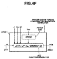
- a target engine torque compensating magnitude generator 370E includes a filter 800 and a function generator 802A.
- the filter 800 the filter Gfil(s) is computed from the equation Eq. 26 and applied to the function generator 802A along with J1, ⁇ w and Gf.
- Target ratio Gt on line 340 is used as an input to the function generator 802A.
- the filter Gfil(s) is used to compute the target engine compensating magnitude ⁇ tTe that can be expressed as the equation Eq. 28.
- a pseudo-differential filter extracted to make phase adjustment of the inertia torque ⁇ Te_inertia and the inertia torque compensating magnitude ⁇ Te_control and target ratio Gt are used to give target engine torque compensating magnitude ⁇ tTe.
- the engine torque is controlled based on this magnitude ⁇ tTe, so that ratio change in CVT can be conducted without any deterioration in operating performance of the engine-CVT drive train.
- ratio change in CVT is performed based on ratio command Gi.
- Pseudo-differential filter extracted to make phase adjustment of the Inertia torque ⁇ Te_inertia and the inertia torque compensating magnitude ⁇ Te_control and ratio command Gi are used to give target engine torque compensating magnitude ⁇ tTe.
- the engine torque is controlled based on this magnitude ⁇ tTe, so that ratio change in CVT can be conducted without any deterioration in operating performance of the engine-CVT drive train.
Landscapes
- Engineering & Computer Science (AREA)
- Chemical & Material Sciences (AREA)
- Combustion & Propulsion (AREA)
- Mechanical Engineering (AREA)
- Transportation (AREA)
- Automation & Control Theory (AREA)
- General Engineering & Computer Science (AREA)
- Control Of Vehicle Engines Or Engines For Specific Uses (AREA)
- Control Of Transmission Device (AREA)
Claims (26)
- Système de commande de transmission comprenant un moteur (1) ayant diverses vitesses de moteur et un élément de commande de couple (1a) actionnable en réponse à un premier signal de commande pour commande le couple de moteur, une CVT (3) comprenant un agencement de commande de rapport ayant un actionneur activé en réponse à un deuxième signal de commande pour établir divers rapports de vitesse entre des arbres d'entrée et de sortie (22, 24) de la CVT (3), et un contrôleur (8) qui émet les premier et deuxième signaux de commande, le contrôleur (8) comprenant un générateur de rapport cible (338) pour générer un rapport cible Gt, et un générateur de commande de rapport (342) pour calculer une commande de rapport Gi en utilisant le rapport cible Gt en tant que variable, et un générateur de correction (384) utilisant comme entrée un paramètre indicateur du couple d'inertie dans la CVT (3) pour générer une correction requise pour obtenir un changement de couple de moteur pour correspondre à l'occurrence du couple d'inertie dans la CVT (3), le contrôleur altérant le premier signal de commande en réponse à la correction, le contrôleur déterminant le deuxième signal de commande en réponse à la commande de rapport Gi,
caractérisé en ce que le contrôleur comprend un générateur (370, 370A, 370B, 370C, 370D, 370E) qui calcule le différentiel de temps ou la vitesse de changement dans la commande de rapport Gi pour déterminer le paramètre indicateur du couple d'inertie dans la CVT (3). - Système de comman de de transmission selon la revendication 1, caractérisé en ce que le générateur de commande de rapport (342) calcule la commande de rapport Gi exprimé comme
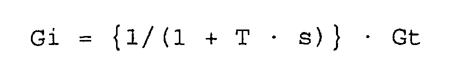
où
T est la fonction de transfert de retard de premier ordre ; et
s est un laplacien. - Système de commande de transmission selon la revendication 1, caractérisé en ce que le générateur de commande de rapport (342) calcule la commande de rapport Gi exprimée comme

où
Gi (k-1) est une commande de rapport calculée la dernière fois,
Gtk est un rapport cible calculé cette fois,
ΔG est une différence entre le rapport réel mesuré cette fois et celui mesuré la dernière fois.
« sign » représente un signe plus ou moins du résultat de calcul entre accolades { } qui suit, et
« min » représente une sélection d'un plus petit de ΔG, et |Gtk - Gi(k-1)|. - Système de commande de transmission selon la revendication 1, caractérisé en ce que le générateur de commande de rapport (342) calcule la commande de rapport Gi exprimée comme

où R1(s) est une expression mathématique d'un modèle canonique qui représente un changement souhaité dans un rapport jusqu'à ce que le rapport cible Gt soit accompli, et
R2(s) est une expression mathématique d'un modèle estimé d'une fonction de transfert du CVT. - Système de commande de transmission selon la revendication, caractérisé en ce que le générateur de commande de rapport (342) calcule la commande de rapport Gi exprimée comme

où :B = exp(-Tsamp/T1) et A = 1 - B.TA est la constante de retard de premier ordre, etTsamp est un temps d'échantillonnage. - Système de commande de tra nsmission selon l'une quelconque des revendications 1 à 5, caractérisé en ce que le générateur qui détermine le paramètre est un générateur de couple d'inertie qui calcule un changement dans la commende de rapport Gi sur une quantité de temps Δt, c'est-à-dire {Gi (k) - Gi (k-1)}/Δt.
- Système de commande de transmission selon l'une quelconque des revendications 1 à 5, caractérisé en ce que le générateur qui détermine le paramètre est un générateur de couple d'inertie (370) qui calcule le terme (dG/dt) exprimé comme

où
C = {1 - exp (-Tsamp/T1)}/Tsamp,
D = (exp(-Tsamp/T1) - 1}/Tsamp, et
E = exp(-Tsamp/T1). - Système de commande de transmission selon l'une quelconque des revendications 1 à 7, caractérisé en ce que le générateur de commande de rapport (342) calcule à partir du rapport cible Gt la commande de rapport Gi qui change de manière progressive.
- Système de commande de transmission selon l'une quelconque des revendications 1 à 7, caractérisé en ce que le générateur de commande de rapport (342) utilise une expression mathématique R1(s) d'un modèle canonique qui représente un changement souhaité dans le rapport jusqu'à ce que le rapport cible Gt soit accompli et une expression mathématique R2(s) d'un modèle estimé d'une fonction de transfert du CVT (3) dans le calcul de la commande de rapport du rapport cible Gt.
- Système de commande de transmission selon l'une quelconque des revendications 1 à 7, caractérisé en ce que le générateur de commande de rapport (342) utilise un filtre qui représente une caractéristique de modèle canonique M(s) exprimée comme

où :T1 est le retard de premier ordre. - Système de commande de transmission selon l'une quelconque des revendications 1 à 10, comprenant en outre :une roue (5) entraînée par un arbre de sortie (24) de la CVT (3) ;un capteur d'accélérateur (9) ;un capteur de vitesse de véhicule (10) ;un capteur de vitesse de moteur (12) ;un capteur de vitesse de roue (11) pour la roue (5) ;le contrôleur (8) étant opérationnel pour entrer des informations d'angle d'accélérateur, de vitesse de véhicule, de vitesse de moteur et de vitesse de roue provenant des capteurs d'accélérateur, de vitesse de véhicule, de vitesse de moteur et de vitesse de roue (9, 10, 11, 12),le contrôleur (8) étant opérationnel pour générer une vitesse cible à partir de l'angle d'accélérateur et de la vitesse de véhicule,le contrôleur (8) étant opérationnel pour générér le rapport cible Gt à partir de la vitesse cible et la vitesse de véhicule ;le contrôleur (8) étant opérationnel pour générer la commande de rapport Gi à partir du rapport cible Gt et la vitesse de roue angulaire ; etle contrôleur (8) étant opérationnel pour générer une correction requise pour obtenir un changement de couple de moteur contre le couple d'inertie.
- Système de commande de transmission selon l'une quelconque des revendications 1 à 11, caractérisé en ce que le générateur (370, 370A, 370B, 370C, 370D, 370E) qui détermine le paramètre est un générateur d'amplitude de compensation de couple de moteur cible qui calcule une amplitude de compensation de couple de moteur cible ΔtTe comme paramètre.
- Système de commande de transmission selon 1 a revendication 12, caractérisé en ce que le générateur d'amplitude de compensation de couple de moteur cible utilise un filtre pseudo différentiel d'ajustement de phase (500, 600, 700, 800) pour l'ajustement de phase entre le couple d'inertie ΔTe_inertia et une amplitude de compensation de couple d'inertie ΔTe_control, et applique le filtre pseudo différentiel d'ajustement de phase (500, 600, 700, 800) sur le rapport cible Gt ou la commande de rapport Gi dans le calcul de l'amplitude de compensation de couple de moteur cible ΔtTe.
- Système de commande de transmission selon la revendication 13, caractérisé en ce que le filtre pseudo différentiel d'ajustement de phase Gfi10(s) (500) comprend une fonction de transfert P(s), qui représente la caractéristique de transfert du rapport cible Gt au rapport réel G, et est appliqué au rapport cible Gt dans le calcul de l'amplitude de compensation de couple de moteur cible ΔtTe.
- Système de commande de transmission selon la revendication 16, caractérisé en ce que la fonction de transfert P(s) est exprimée comme

où :GCVT(s) est une dynamique de la CVT (3) ; etGLOGIC est une constante de temps de rapport de logique de commande de changement. - Système de commande de transmission selon la revendication 15, caractérisé en ce que la dynamique G CVT(s) de la CVT (3) est exprimée comme
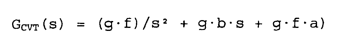
où :a, b, g et f sont des paramètres ; ets est un laplacien. - Système de commande de transmission selon la revendication 16, caractérisé en ce que les paramètres a et b restent inchangés sur la variation dans la pression de ligne, mais s'altèrent selon la température d'huile et la charge, en ce que le paramètre g est proportionnel à la pression de ligne et, avec la même pression de ligne, le paramètre g augmente alors que la température d'huile augment, et en ce que le paramètre f augmente à mesure que la vitesse de véhicule augmente.
- Système de commande de transmission selon la revendication 15 ou 16, caractérisé en ce que la constante de temps GLOGIC est donnée par des programmes de calcule de la logique de commande de changement de rapport.
- Système de commande de transmission selon la revendication 13, caractérisé en ce que le filtre pseudo différentiel d'ajustement de phase Gfil&(s) (600) comprend une fonction de transfert Q(s), qui représente une caractéristique de transfert à partir de la commande de rapport Gi vers le rapport réel G, et une autre fonction de transfert M(s), qui représente la caractéristique de transfert à partir du rapport cible Gt vers la commande de rapport Gi, et en ce que le filtre pseudo différentiel d'ajustement de phase Gfil1(s) (600) est appliqué sur le rapport cible Gt dans le calcul de l'amplitude de compensation de couple de moteur cible ΔtTe.
- Système de commande de transmission selon la revendication 13, caractérisé en ce que le filtre pseudo différentiel d'ajustement de phase Gfil2(s) (700) comprend une fonction de transfert Q(s), qui représente une caractéristique de transfert depuis la commande de rapport Gi vers le rapport réel G, et en ce que le filtre pseudo différentiel d'ajustement de phase Gfill(s) (600) est appliqué sur la commande de rapport Gi dans le calcul de l'amplitude de compensation de couple de moteur cible ΔtTe.
- Système de commande de transmission selon la revendication 13, caractérisé en ce que le filtre pseudo différentiel d'ajustement de phase Gfil(s) (800) est donné par l'approximation d'ordre faible, qui comprend une constante de temps Tred qui varie selon la vitesse du moteur et la charge du moteur, et en ce que le filtre pseudo différentiel d'ajustement de phase Gfil(s) (800) est appliqué sur la commande de rapport Gi ou le rapport cible Gt dans le calcul de l'amplitude de compensation de couple de moteur cible ΔtTe.
- Système de commande de transmission selon la revendication 13, caractérisé en ce que le filtre pseudo différentiel d'ajustement de phase Gfil0(s) implique un retard de phase dû à la caractéristique de transfert à partir du rapport cible Gt vers le rapport réel G dans la CVT (3).
- Système de commande de transmission selon la revendication 13, caractérisé en ce que le filtre pseudo différentiel d'ajustement de phase Gfil1(s) ou Gil2(s) implique un retard de phase dû à la caractéristique de transfert à partir de la commande de rapport Gi vers le rapport réel G dans la CVT (3).
- Système de commande de transmission selon la revendication 13, caractérisé en ce que le filtre pseudo différentiel d'ajustement de phase Gfil(s) est donné par une approximation d'ordre faible.
- Système de commande de transmission selon l'une quelconque des revendications 13 à 24, caractérisé en ce qu'un ou des paramètres (TE, TETC, TD, Tred) utilisés dans une expression mathématique du filtre pseudo différentiel d'ajustement de phase sont donnés en fonction des conditions de fonctionnement de la transmission de véhicule.
- Système de commande de transmission selon la revendication 25, caractérisé en ce que chacun des paramètres utilisés dans l'expression mathématique du filtre pseudo différentiel d'ajustement de phase est donné en fonction des conditions de fonctionnement du moteur.
Priority Applications (1)
| Application Number | Priority Date | Filing Date | Title |
|---|---|---|---|
| EP04017990A EP1470947A3 (fr) | 1997-12-19 | 1998-12-18 | Commande de chaîne cinématique pour moteur et transmission à variation continue |
Applications Claiming Priority (2)
| Application Number | Priority Date | Filing Date | Title |
|---|---|---|---|
| JP35087497 | 1997-12-19 | ||
| JP35087497 | 1997-12-19 |
Related Child Applications (1)
| Application Number | Title | Priority Date | Filing Date |
|---|---|---|---|
| EP04017990A Division EP1470947A3 (fr) | 1997-12-19 | 1998-12-18 | Commande de chaîne cinématique pour moteur et transmission à variation continue |
Publications (3)
| Publication Number | Publication Date |
|---|---|
| EP0925992A2 EP0925992A2 (fr) | 1999-06-30 |
| EP0925992A3 EP0925992A3 (fr) | 2001-04-18 |
| EP0925992B1 true EP0925992B1 (fr) | 2006-03-15 |
Family
ID=18413483
Family Applications (2)
| Application Number | Title | Priority Date | Filing Date |
|---|---|---|---|
| EP98124086A Expired - Lifetime EP0925992B1 (fr) | 1997-12-19 | 1998-12-18 | Commande de chaîne cinématique pour moteur et transmission à variation continue |
| EP04017990A Withdrawn EP1470947A3 (fr) | 1997-12-19 | 1998-12-18 | Commande de chaîne cinématique pour moteur et transmission à variation continue |
Family Applications After (1)
| Application Number | Title | Priority Date | Filing Date |
|---|---|---|---|
| EP04017990A Withdrawn EP1470947A3 (fr) | 1997-12-19 | 1998-12-18 | Commande de chaîne cinématique pour moteur et transmission à variation continue |
Country Status (4)
| Country | Link |
|---|---|
| US (1) | US6272414B1 (fr) |
| EP (2) | EP0925992B1 (fr) |
| KR (1) | KR100302425B1 (fr) |
| DE (1) | DE69833827T2 (fr) |
Families Citing this family (22)
| Publication number | Priority date | Publication date | Assignee | Title |
|---|---|---|---|---|
| JP3460576B2 (ja) * | 1998-04-28 | 2003-10-27 | トヨタ自動車株式会社 | 無段変速機を備えた車両の制御装置 |
| JP3360643B2 (ja) | 1999-04-06 | 2002-12-24 | トヨタ自動車株式会社 | 動力源と無段変速機を備えた車両の制御装置 |
| JP3572612B2 (ja) * | 2000-07-31 | 2004-10-06 | 日産自動車株式会社 | 変速比無限大無段変速機のイナーシャトルク補償制御装置 |
| US6379281B1 (en) * | 2000-09-08 | 2002-04-30 | Visteon Global Technologies, Inc. | Engine output controller |
| JP3791315B2 (ja) * | 2000-09-18 | 2006-06-28 | 日産自動車株式会社 | 駆動力制御装置 |
| JP2002138872A (ja) * | 2000-10-30 | 2002-05-17 | Nissan Motor Co Ltd | ディーゼルエンジン搭載車両の駆動力制御装置 |
| US6679806B2 (en) * | 2001-01-03 | 2004-01-20 | S & S Trust | Soft shift system and method |
| US6839617B2 (en) * | 2002-04-11 | 2005-01-04 | Nissan Motor Co., Ltd. | Extension of operating range of feedback in CVT ratio control |
| US6853587B2 (en) * | 2002-06-21 | 2005-02-08 | Micron Technology, Inc. | Vertical NROM having a storage density of 1 bit per 1F2 |
| RU2005132989A (ru) | 2003-03-27 | 2006-05-27 | Торотрак (Дивелопмент) Лимитед (Gb) | Способ управления непрерывно регулируемой трансмиссией |
| DE10361285B4 (de) * | 2003-12-24 | 2020-07-09 | Jochen Strenkert | Vorrichtung mit einer Einheit zum Betätigen eines stufenlosen Kraftfahrzeuggetriebes |
| US7243011B2 (en) * | 2004-05-21 | 2007-07-10 | General Motors Corporation | Hybrid transmission launch algorithm |
| GB0420007D0 (en) * | 2004-09-09 | 2004-10-13 | Torotrak Dev Ltd | A motor vehicle powertrain and a method and apparatus for control thereof |
| JP4301224B2 (ja) * | 2005-02-16 | 2009-07-22 | トヨタ自動車株式会社 | 自動車およびその制御方法 |
| JP2008070224A (ja) * | 2006-09-14 | 2008-03-27 | Denso Corp | 車載用角速度センサ |
| US20080081734A1 (en) * | 2006-09-29 | 2008-04-03 | Caterpillar Inc. | Power system |
| KR100862432B1 (ko) | 2006-12-15 | 2008-10-08 | 현대자동차주식회사 | Etc가 탑재된 하이브리드 전기자동차의 엔진 토크 제어방법 |
| JP4577336B2 (ja) * | 2007-08-09 | 2010-11-10 | 日産自動車株式会社 | 電動車両における電動機の制御装置 |
| JP4561889B2 (ja) * | 2008-07-01 | 2010-10-13 | トヨタ自動車株式会社 | 出力トルクの算出装置 |
| KR101055020B1 (ko) * | 2008-12-02 | 2011-08-05 | 현대자동차주식회사 | 하이브리드 차량의 변속 제어방법 |
| US9168825B2 (en) | 2009-05-15 | 2015-10-27 | Ford Global Technologies, Llc | Hybrid electric vehicle and method for controlling a powertrain therein |
| US20190283766A1 (en) * | 2018-03-19 | 2019-09-19 | Uber Technologies, Inc. | Drivetrain compensation for autonomous vehicles |
Family Cites Families (14)
| Publication number | Priority date | Publication date | Assignee | Title |
|---|---|---|---|---|
| JPH0672655B2 (ja) | 1988-12-16 | 1994-09-14 | 日産自動車株式会社 | トロイダル型無段変速機 |
| JPH07113410B2 (ja) | 1988-12-16 | 1995-12-06 | 日産自動車株式会社 | トロイダル型無段変速機 |
| JP2606383B2 (ja) | 1989-08-30 | 1997-04-30 | 日産自動車株式会社 | トロイダル型無段変速機 |
| JPH0823386B2 (ja) | 1989-09-26 | 1996-03-06 | 日産自動車株式会社 | 摩擦車式無段変速機 |
| US5382205A (en) * | 1991-03-29 | 1995-01-17 | Mitsubishi Jidosha Kogyo Kabushiki Kaisha | Control device for an internal combustion engine and a continuous variable transmission |
| JP2848101B2 (ja) | 1991-04-19 | 1999-01-20 | 三菱自動車工業株式会社 | 内燃機関と連続可変変速機との制御装置 |
| US5083474A (en) | 1991-06-04 | 1992-01-28 | Axicon Gear Company | Zero transmission error gearing |
| JP3459290B2 (ja) | 1994-02-28 | 2003-10-20 | 株式会社日立ユニシアオートモティブ | 無段変速機付き車両の制御装置 |
| JP3460341B2 (ja) | 1994-11-28 | 2003-10-27 | 日産自動車株式会社 | 摩擦車式無段変速機の変速制御装置 |
| JPH08156652A (ja) * | 1994-12-07 | 1996-06-18 | Hitachi Ltd | 車両の駆動トルク制御装置 |
| JPH08177541A (ja) | 1994-12-27 | 1996-07-09 | Nissan Motor Co Ltd | エンジントルク制御装置 |
| JP3211638B2 (ja) * | 1995-08-31 | 2001-09-25 | トヨタ自動車株式会社 | 車両の制御装置 |
| JP3341633B2 (ja) * | 1997-06-27 | 2002-11-05 | 日産自動車株式会社 | 無段変速機搭載車の変速ショック軽減装置 |
| JP3460576B2 (ja) * | 1998-04-28 | 2003-10-27 | トヨタ自動車株式会社 | 無段変速機を備えた車両の制御装置 |
-
1998
- 1998-12-18 DE DE69833827T patent/DE69833827T2/de not_active Expired - Lifetime
- 1998-12-18 EP EP98124086A patent/EP0925992B1/fr not_active Expired - Lifetime
- 1998-12-18 US US09/215,335 patent/US6272414B1/en not_active Expired - Lifetime
- 1998-12-18 EP EP04017990A patent/EP1470947A3/fr not_active Withdrawn
- 1998-12-19 KR KR1019980056470A patent/KR100302425B1/ko not_active IP Right Cessation
Also Published As
| Publication number | Publication date |
|---|---|
| DE69833827T2 (de) | 2006-08-17 |
| KR100302425B1 (ko) | 2001-11-22 |
| EP0925992A3 (fr) | 2001-04-18 |
| EP1470947A3 (fr) | 2011-10-19 |
| EP1470947A2 (fr) | 2004-10-27 |
| DE69833827D1 (de) | 2006-05-11 |
| KR19990063247A (ko) | 1999-07-26 |
| EP0925992A2 (fr) | 1999-06-30 |
| US6272414B1 (en) | 2001-08-07 |
Similar Documents
| Publication | Publication Date | Title |
|---|---|---|
| EP0925992B1 (fr) | Commande de chaîne cinématique pour moteur et transmission à variation continue | |
| US5184577A (en) | Running state control system for motor vehicle | |
| EP0879731B1 (fr) | Dispositif de commande pour moteur et transmission à variation continue automatique à commande électronique | |
| US6379281B1 (en) | Engine output controller | |
| US6220987B1 (en) | Automatic transmission ratio change schedules based on desired powertrain output | |
| US6991584B2 (en) | Control of powertrain smoothness using output torque sensing and input torque control | |
| US6502027B2 (en) | Road gradient detecting device and starter clutch controlling device | |
| US6701246B2 (en) | Engine torque determination for powertrain with torque converter | |
| US6181020B1 (en) | Integrated driving torque control system for automotive vehicles with continuously variable automatic transmission | |
| US5036728A (en) | Engine control system for vehicle with automatic transmission | |
| US6440041B1 (en) | Method of controlling engine torque during launch from neutral idle operation | |
| US8935063B2 (en) | Control apparatus and control method for vehicle | |
| US8498789B2 (en) | Control apparatus and control method for drive source | |
| US20100274460A1 (en) | Control apparatus and control method for power source | |
| US5665021A (en) | Toroidal continuous variable transmission | |
| US7983826B2 (en) | Control apparatus and control method for drive source | |
| US6364812B1 (en) | Automatic transmission dynamic electronic pressure control based on desired powertrain output | |
| JPS60192155A (ja) | 車両用スリツプ防止装置 | |
| US6398691B1 (en) | Speed ratio control device | |
| US8019524B2 (en) | Control apparatus for driving source | |
| JP3623077B2 (ja) | 自動変速機の変速過渡制御装置 | |
| JP3323969B2 (ja) | 自動変速機の出力制御装置 | |
| JPS58193961A (ja) | 自動車用自動変速装置 | |
| JP3458696B2 (ja) | 車両の駆動力制御装置 | |
| JPH0627290U (ja) | 自動変速機の出力制御装置 |
Legal Events
| Date | Code | Title | Description |
|---|---|---|---|
| PUAI | Public reference made under article 153(3) epc to a published international application that has entered the european phase |
Free format text: ORIGINAL CODE: 0009012 |
|
| 17P | Request for examination filed |
Effective date: 19981218 |
|
| AK | Designated contracting states |
Kind code of ref document: A2 Designated state(s): DE FR GB |
|
| AX | Request for extension of the european patent |
Free format text: AL;LT;LV;MK;RO;SI |
|
| PUAL | Search report despatched |
Free format text: ORIGINAL CODE: 0009013 |
|
| AK | Designated contracting states |
Kind code of ref document: A3 Designated state(s): AT BE CH CY DE DK ES FI FR GB GR IE IT LI LU MC NL PT SE |
|
| AX | Request for extension of the european patent |
Free format text: AL;LT;LV;MK;RO;SI |
|
| AKX | Designation fees paid |
Free format text: DE FR GB |
|
| 17Q | First examination report despatched |
Effective date: 20021230 |
|
| RAP1 | Party data changed (applicant data changed or rights of an application transferred) |
Owner name: NISSAN MOTOR CO., LTD. |
|
| RIN1 | Information on inventor provided before grant (corrected) |
Inventor name: ASHIZAWA, HIROYUKI Inventor name: NAKAMURA, HIDEO Inventor name: SUZUKI, KEISUKE Inventor name: TAKAHASHI, NOBUTAKA |
|
| GRAP | Despatch of communication of intention to grant a patent |
Free format text: ORIGINAL CODE: EPIDOSNIGR1 |
|
| GRAS | Grant fee paid |
Free format text: ORIGINAL CODE: EPIDOSNIGR3 |
|
| GRAA | (expected) grant |
Free format text: ORIGINAL CODE: 0009210 |
|
| RIC1 | Information provided on ipc code assigned before grant |
Ipc: B60W 50/00 20060101ALI20060119BHEP Ipc: B60W 20/00 20060101ALI20060119BHEP Ipc: B60W 10/10 20060101ALI20060119BHEP Ipc: B60W 10/04 20060101AFI20060119BHEP |
|
| AK | Designated contracting states |
Kind code of ref document: B1 Designated state(s): DE FR GB |
|
| REG | Reference to a national code |
Ref country code: GB Ref legal event code: FG4D |
|
| REF | Corresponds to: |
Ref document number: 69833827 Country of ref document: DE Date of ref document: 20060511 Kind code of ref document: P |
|
| ET | Fr: translation filed | ||
| PLBE | No opposition filed within time limit |
Free format text: ORIGINAL CODE: 0009261 |
|
| STAA | Information on the status of an ep patent application or granted ep patent |
Free format text: STATUS: NO OPPOSITION FILED WITHIN TIME LIMIT |
|
| 26N | No opposition filed |
Effective date: 20061218 |
|
| REG | Reference to a national code |
Ref country code: FR Ref legal event code: PLFP Year of fee payment: 18 |
|
| REG | Reference to a national code |
Ref country code: FR Ref legal event code: PLFP Year of fee payment: 19 |
|
| REG | Reference to a national code |
Ref country code: FR Ref legal event code: PLFP Year of fee payment: 20 |
|
| PGFP | Annual fee paid to national office [announced via postgrant information from national office to epo] |
Ref country code: FR Payment date: 20171113 Year of fee payment: 20 Ref country code: DE Payment date: 20171212 Year of fee payment: 20 |
|
| PGFP | Annual fee paid to national office [announced via postgrant information from national office to epo] |
Ref country code: GB Payment date: 20171213 Year of fee payment: 20 |
|
| REG | Reference to a national code |
Ref country code: DE Ref legal event code: R071 Ref document number: 69833827 Country of ref document: DE |
|
| REG | Reference to a national code |
Ref country code: GB Ref legal event code: PE20 Expiry date: 20181217 |
|
| PG25 | Lapsed in a contracting state [announced via postgrant information from national office to epo] |
Ref country code: GB Free format text: LAPSE BECAUSE OF EXPIRATION OF PROTECTION Effective date: 20181217 |