EP0925992B1 - Engine-CVT drive train control system - Google Patents
Engine-CVT drive train control system Download PDFInfo
- Publication number
- EP0925992B1 EP0925992B1 EP98124086A EP98124086A EP0925992B1 EP 0925992 B1 EP0925992 B1 EP 0925992B1 EP 98124086 A EP98124086 A EP 98124086A EP 98124086 A EP98124086 A EP 98124086A EP 0925992 B1 EP0925992 B1 EP 0925992B1
- Authority
- EP
- European Patent Office
- Prior art keywords
- ratio
- drive train
- cvt
- control system
- target
- Prior art date
- Legal status (The legal status is an assumption and is not a legal conclusion. Google has not performed a legal analysis and makes no representation as to the accuracy of the status listed.)
- Expired - Lifetime
Links
Images


Classifications
-
- B—PERFORMING OPERATIONS; TRANSPORTING
- B60—VEHICLES IN GENERAL
- B60W—CONJOINT CONTROL OF VEHICLE SUB-UNITS OF DIFFERENT TYPE OR DIFFERENT FUNCTION; CONTROL SYSTEMS SPECIALLY ADAPTED FOR HYBRID VEHICLES; ROAD VEHICLE DRIVE CONTROL SYSTEMS FOR PURPOSES NOT RELATED TO THE CONTROL OF A PARTICULAR SUB-UNIT
- B60W10/00—Conjoint control of vehicle sub-units of different type or different function
- B60W10/04—Conjoint control of vehicle sub-units of different type or different function including control of propulsion units
- B60W10/06—Conjoint control of vehicle sub-units of different type or different function including control of propulsion units including control of combustion engines
-
- B—PERFORMING OPERATIONS; TRANSPORTING
- B60—VEHICLES IN GENERAL
- B60W—CONJOINT CONTROL OF VEHICLE SUB-UNITS OF DIFFERENT TYPE OR DIFFERENT FUNCTION; CONTROL SYSTEMS SPECIALLY ADAPTED FOR HYBRID VEHICLES; ROAD VEHICLE DRIVE CONTROL SYSTEMS FOR PURPOSES NOT RELATED TO THE CONTROL OF A PARTICULAR SUB-UNIT
- B60W10/00—Conjoint control of vehicle sub-units of different type or different function
- B60W10/04—Conjoint control of vehicle sub-units of different type or different function including control of propulsion units
-
- B—PERFORMING OPERATIONS; TRANSPORTING
- B60—VEHICLES IN GENERAL
- B60W—CONJOINT CONTROL OF VEHICLE SUB-UNITS OF DIFFERENT TYPE OR DIFFERENT FUNCTION; CONTROL SYSTEMS SPECIALLY ADAPTED FOR HYBRID VEHICLES; ROAD VEHICLE DRIVE CONTROL SYSTEMS FOR PURPOSES NOT RELATED TO THE CONTROL OF A PARTICULAR SUB-UNIT
- B60W10/00—Conjoint control of vehicle sub-units of different type or different function
- B60W10/10—Conjoint control of vehicle sub-units of different type or different function including control of change-speed gearings
- B60W10/101—Infinitely variable gearings
- B60W10/108—Friction gearings
- B60W10/109—Friction gearings of the toroïd type
-
- B—PERFORMING OPERATIONS; TRANSPORTING
- B60—VEHICLES IN GENERAL
- B60W—CONJOINT CONTROL OF VEHICLE SUB-UNITS OF DIFFERENT TYPE OR DIFFERENT FUNCTION; CONTROL SYSTEMS SPECIALLY ADAPTED FOR HYBRID VEHICLES; ROAD VEHICLE DRIVE CONTROL SYSTEMS FOR PURPOSES NOT RELATED TO THE CONTROL OF A PARTICULAR SUB-UNIT
- B60W30/00—Purposes of road vehicle drive control systems not related to the control of a particular sub-unit, e.g. of systems using conjoint control of vehicle sub-units, or advanced driver assistance systems for ensuring comfort, stability and safety or drive control systems for propelling or retarding the vehicle
- B60W30/18—Propelling the vehicle
- B60W30/1819—Propulsion control with control means using analogue circuits, relays or mechanical links
-
- F—MECHANICAL ENGINEERING; LIGHTING; HEATING; WEAPONS; BLASTING
- F16—ENGINEERING ELEMENTS AND UNITS; GENERAL MEASURES FOR PRODUCING AND MAINTAINING EFFECTIVE FUNCTIONING OF MACHINES OR INSTALLATIONS; THERMAL INSULATION IN GENERAL
- F16H—GEARING
- F16H61/00—Control functions within control units of change-speed- or reversing-gearings for conveying rotary motion ; Control of exclusively fluid gearing, friction gearing, gearings with endless flexible members or other particular types of gearing
- F16H61/66—Control functions within control units of change-speed- or reversing-gearings for conveying rotary motion ; Control of exclusively fluid gearing, friction gearing, gearings with endless flexible members or other particular types of gearing specially adapted for continuously variable gearings
-
- B—PERFORMING OPERATIONS; TRANSPORTING
- B60—VEHICLES IN GENERAL
- B60L—PROPULSION OF ELECTRICALLY-PROPELLED VEHICLES; SUPPLYING ELECTRIC POWER FOR AUXILIARY EQUIPMENT OF ELECTRICALLY-PROPELLED VEHICLES; ELECTRODYNAMIC BRAKE SYSTEMS FOR VEHICLES IN GENERAL; MAGNETIC SUSPENSION OR LEVITATION FOR VEHICLES; MONITORING OPERATING VARIABLES OF ELECTRICALLY-PROPELLED VEHICLES; ELECTRIC SAFETY DEVICES FOR ELECTRICALLY-PROPELLED VEHICLES
- B60L2240/00—Control parameters of input or output; Target parameters
- B60L2240/40—Drive Train control parameters
- B60L2240/48—Drive Train control parameters related to transmissions
- B60L2240/486—Operating parameters
-
- B—PERFORMING OPERATIONS; TRANSPORTING
- B60—VEHICLES IN GENERAL
- B60W—CONJOINT CONTROL OF VEHICLE SUB-UNITS OF DIFFERENT TYPE OR DIFFERENT FUNCTION; CONTROL SYSTEMS SPECIALLY ADAPTED FOR HYBRID VEHICLES; ROAD VEHICLE DRIVE CONTROL SYSTEMS FOR PURPOSES NOT RELATED TO THE CONTROL OF A PARTICULAR SUB-UNIT
- B60W2510/00—Input parameters relating to a particular sub-units
- B60W2510/10—Change speed gearings
- B60W2510/1005—Transmission ratio engaged
-
- B—PERFORMING OPERATIONS; TRANSPORTING
- B60—VEHICLES IN GENERAL
- B60W—CONJOINT CONTROL OF VEHICLE SUB-UNITS OF DIFFERENT TYPE OR DIFFERENT FUNCTION; CONTROL SYSTEMS SPECIALLY ADAPTED FOR HYBRID VEHICLES; ROAD VEHICLE DRIVE CONTROL SYSTEMS FOR PURPOSES NOT RELATED TO THE CONTROL OF A PARTICULAR SUB-UNIT
- B60W2540/00—Input parameters relating to occupants
- B60W2540/10—Accelerator pedal position
-
- B—PERFORMING OPERATIONS; TRANSPORTING
- B60—VEHICLES IN GENERAL
- B60W—CONJOINT CONTROL OF VEHICLE SUB-UNITS OF DIFFERENT TYPE OR DIFFERENT FUNCTION; CONTROL SYSTEMS SPECIALLY ADAPTED FOR HYBRID VEHICLES; ROAD VEHICLE DRIVE CONTROL SYSTEMS FOR PURPOSES NOT RELATED TO THE CONTROL OF A PARTICULAR SUB-UNIT
- B60W2710/00—Output or target parameters relating to a particular sub-units
- B60W2710/06—Combustion engines, Gas turbines
- B60W2710/0677—Engine power
Landscapes
- Engineering & Computer Science (AREA)
- Chemical & Material Sciences (AREA)
- Combustion & Propulsion (AREA)
- Mechanical Engineering (AREA)
- Transportation (AREA)
- Automation & Control Theory (AREA)
- General Engineering & Computer Science (AREA)
- Control Of Vehicle Engines Or Engines For Specific Uses (AREA)
- Control Of Transmission Device (AREA)
Description
- The present invention relates to a drive train control system having the features contained in the preamble portion of
claim 1. Such a system is disclosed inEP 0 530 381 A1. - In the following description, the term "engine" is herein used to mean an internal combustion engine, an electric motor and a hybrid power unit that includes an internal combustion engine and an electric motor.
- In an automotive drive train including an engine and a CVT, varying a CVT ratio, i.e., a ratio = (input speed)/(output speed), brings about the following phenomena.
- (1) At acceleration, varying a CVT ratio in a shift-down direction causes a drop in drive torque for acceleration during a period of shifting owing to an increase in equivalent inertia in drive train, failing to meet power demand for acceleration.
- (2) During a shift from acceleration mode to an ordinary drive mode, varying CVT ratio in a shift-up direction causes an increase in drive torque for acceleration during a period of shifting owing to a reduction in equivalent inertia in drive train, providing an unexpected acceleration feel to the vehicle driver.
- US-A 5,790,968 (JP-A 7-239002) discloses a CVT ratio rate control system that controls a CVT ratio rate (= speed at which CVT ratio changes) based on consideration of change in inertia torque, that is, apparent torque derived due to changes in equivalent inertia. This known CVT control system adjusts CVT ratio rate in response to an output speed of CVT in such a manner as to restrain inertia torque from exceeding a predetermined value.
- JP-A 8-177541 discloses an engine torque control system for an engine-CVT drive train. According to this known engine control system, upon occurrence of a downshift command for acceleration, a ratio rate due to the downshift is anticipated and a drop, in amount, of engine torque is anticipated based on the anticipated ratio rate. During a period between the downshift command and the subsequent initiation of ratio change, the engine Ignition timing is retarded in accordance with the anticipated drop of engine torque for a reduction of the engine torque. After initiation of the ratio change in the downshift direction, the amount of the ignition timing retard is gradually reduced in accordance with the actual CVT ratio rate. This control is intended to provide smooth increase in engine torque upon acceleration.
- The known CVT ratio rate control system may not sufficiently meet driver's acceleration demand because drop in CVT ratio rate to suppress inertia torque causes slow acceleration during CVT ratio change in downshift direction.
- Thus, it would be desired to make compensation for reduction in inertia torque with CVT ratio rate maintained to meet driver's acceleration demand.
- Inertia torque ΔTe_inertia, which is derived from changes in equivalent inertia in engine caused by CVT ratio changes, can be expressed as,

where: J1 is moment of inertia of the CVT input shaft due to masses of engine and intermediate components between the engine and the CVT input shaft,
Gf is a final drive reduction ratio,
ωw is angular speed of a wheel driven by the final drive, and
G is a ratio that is a speed ratio between the CVT input and output shafts. - Variations of the speeds of input and output shafts of CVT are measured for calculation of CVT ratio. These measured values of the speeds may involve measurement errors and noises that are not predictable and difficult to remove by the present technology. Deviations of calculated values of the CVT ratio from variations of the CVT ratio are subject to such measurement errors and noises. Unless appropriately processed, the calculated values of the CVT ratio cannot be regarded as G in the equation (1). If these values are substituted for G, calculated values of dG/dt are greatly deviated from variations of dG/dt, causing great deviations of calculated values of TI from variations of TI. Thus, using the calculated values of TI in altering engine torque will fail to meet driver's acceleration demand during downshift for acceleration.
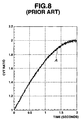
- Figures 8 to 13 show simulation results. In Figure 8, the reference character A shows plotting of simulated measures resulting from superimposing random noise with the probability density of the normal distribution, where variance is 0.01, upon real variations of CVT ratio from 1 to 2 against time over period of 2 seconds. In Figure 9(A), a curve B connects values resulting from repeating subtraction of a previously sampled old value of the real variations of CVT ratio from a currently sampled new value thereof over 0 to 2 seconds. In Figure 9(B), the reference character C shows plotting of values resulting from repeating subtraction of a previously sampled old value of the measures in Figure 8 from a currently sampled new value thereof over 0 to 2 seconds. The values shown in Figures 9(A) may be regarded as dG/dt, where the real variations are substituted for G in equation (1). The values shown in Figure 9(B) may be regarded as dG/dt, where the simulated measures shown in Figure 8 are substituted for G in equation (1). Comparing Figure 9(B) with Figure 9(A) reveals that the values of Figure 9(a) deviates from the corresponding values of Figure 9(B) too much to represent the real variations of dG/dt. This means that values resulting from calculating equation (1) after substitution of the values of Figure 9(B) for dG/dt will fail to represent real variations of the inertia torque ΔTe_inertia.
- Filters are often used to process measures for removal or at least reduction of noise component.
- In Figure 10, a curve as indicated by the reference character a shows real variations of the CVT ratio from 1 to 2 over a period of 2 seconds, while a curve indicated by the reference character b shows values resulting from filtering the real variations. Comparing the curve b with the curve a clearly shows that the filtering has caused a phase shift.
- The measures of the CVT ratio as shown at A in Figure 8 are subjected to the filtering process to give filtered measures. In Figure 11, the reference character C1 shows plotting of values resulting from repeating subtraction of a previously sampled old value of the filtered measures from a currently sampled new value thereof over 2 seconds. The curve B in Figure 9(A) is drawn in Figure 11 for comparison with the plotting C1. Comparing the plotting C1 in Figure 11 with the plotting C in Figure 9(B) reveals that the noise component has been reduced. However, the values on the plotting C1 shown in Figure 11 still suffer from undesired variations, so that they cannot be used as substitution for dG/dt in the equation (1).
- Figures 12 and 13 illustrate test results from signal processing with another filter, which has a different characteristic.
- In Figure 12, a curve a shows real variations of the CVT ratio from 1 to 2 over a period of 2 seconds, while a curve indicated by the reference character b1 shows values resulting from filtering the real variations. Comparing the curve b1 with the curve b shown in Figure 10 clearly shows that this filtering has caused a greater phase shift.
- The measures of the CVT ratio as shown at A in Figure 8 are subjected to the filtering by this another filter to give filtered measures. In Figure 13, the reference character C2 shows plotting of values resulting from repeating subtraction of a previously sampled old value of the filtered measures from a currently sampled new value thereof over 2 seconds. The curve B of Figure 9(A) is drawn in Figure 13 for comparison with the plotting C2. Comparing the plotting C2 in Figure 13 with the plotting C1 in Figure 11 reveals that the noise component has been reduced. However, the deviation from the curve B has increased, so that the values on the plotting C2 cannot be used as substitution for dG/dt in the equation (1).
- US 5,305,662 discloses a control device for an internal combustion engine and a CVT which enables well responsible transmission control.
- There is a need to meet driver's demand or expectation for vehicle performance during variations of CVT ratio. An object of the present invention therefore is to improve a control system for a vehicle drive train including an engine and a CVT such that the above-mentioned need is fulfilled.
- Said object is achieved according to the invention by the subject-matter of
claim 1. Preferred embodiments of the invention are indicated in the depending claims. - In the following, the invention is explained in detail by way of example and with reference to the accompanying drawings, in which
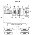
- Figure 1 is a block diagram showing the relationship between a controller and a vehicle drive train including an engine and a CVT.
- Figure 2 is a drawing of a fragment of the engine control system.
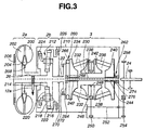
- Figure 3 is a schematic view of the CVT with a forward/reverse changeover mechanism and a torque converter.
- Figure 4 is a control diagram showing control performed in the controller.
- Figure 4A is a portion of Figure 4 but incorporating modification implementing another embodiment.
- Figure 48 is a portion of Figure 4A.
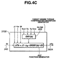
- Figure 4C is a similar view to Figure 4B illustrating still another embodiment.
- Figure 4D is a portion of Figure 4 but incorporating modification implementing further embodiment.
- Figure 4E is a portion of Figure 4D.
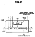
- Figure 4F is a similar view Figure 4E illustrating another further embodiment.
- Figure 4G is a similar view to Figure 4B illustrating still further embodiment.
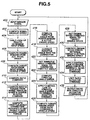
- Figure 5 is a flow chart of a control routine.
- Figure 6 is a CVT map illustrating variations a CVT input shaft speed versus variations of the vehicle speed against variations of accelerator pedal position or angle.
- Figure 7 is an engine map illustrating variations of engine torque versus variations of throttle valve angle against variations of engine speed.
- Figure 8 shows plotting A of simulated measures resulting from superimposing random noise upon real variations of CVT ratio from 1 to 2 against time over period of 2 seconds.
- Figure 9(A) shows a curve B that connects values resulting from repeating subtraction of a previously sampled old value of the real variations of CVT ratio from a currently sampled new value thereof over 0 to 2 seconds.
- Figure 9(B) shows plotting C of values resulting from repeating subtraction of a previously sampled old value of the measures in Figure 8 from a currently sampled new value thereof over 0 to 2 seconds.
- Figure 10 shows a curve a representing real variations of the CVT ratio from 1 to 2 over a period of 2 seconds, and a curve b representing values resulting from filtering the real varlations.
- Figure 11 shows plotting C1 of values resulting from repeating subtraction of a previously sampled old value of the filtered measures from a currently sampled new value thereof over 2 seconds together with the curve B shown in Figure 9(A).
- Figure 12 shows a curve a representing real variations of the CVT ratio from 1 to 2 over a period of 2 seconds, and a curve b1 representing values resulting from filtering the real variations.
- Figure 13 shows plotting C2 of values resulting from repeating subtraction of a previously sampled old value of the filtered measures from a currently sampled new value thereof over 2 seconds together with the curve B shown in Figure 9(A).
- Figure 14 is a diagram illustrating variations of a time constant TE of intake air admission delay against engine speed (Ne) and engine load.
- Figure 15 is a diagram illustrating of a dead time TD of engine torque against engine speed (Ne).
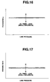
- Figure 16 is a diagram illustrating variations of a parameter a against line pressure of the transmission, oil temperature and load.
- Figure 17 is a diagram illustrating variations of a parameter b against line pressure of the transmission, oil temperature and load.
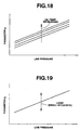
- Figure 18 is a diagram illustrating variations of a parameter g against line pressure of the transmission and oil temperature thereof.
- Figure 19 is a diagram illustrating variations of the parameter g against line pressure of the transmission and load.
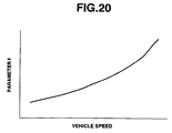
- Figure 20 is a diagram illustrating variations of a parameter f against vehicle speed (VSP).
- Figure 21 is a diagram illustrating variations of a parameter Tred against engine speed (Ne) and load.
- Figure 22 is a diagram illustrating variations of the parameter Tred against engine speed (Ne).
- Figure 1 illustrates an engine-CVT drive train for a passenger automotive vehicle with a manually operable accelerator or gas pedal that has various depressed positions in response to varying operator power demand. The drive train indudes an
engine 1 and a continuously variable transmission (CVT) 3. It will be understood that the present invention is operational with any type of engine whose torque output can be controlled, including a gasoline engine, a diesel engine, an electric motor, and hybrid power unit. The present invention is operational with any type of CVT in which ratio rate can be controlled, including hydrostatic and friction CVTs. Examples of the friction CVTs are a V-belt CVT with a V-belt interconnecting an input pulley and an output pulley and a toroidal CVT with friction rollers between and in engagement with a set of coaxial toric input and output discs. - A torque control element controls the torque output of the
engine 1. In the case of a gasoline engine, the torque control element is athrottle valve 1a that opens in degrees to regulate intake air, in amount, admitted to the engine. The torque control is not limited to regulating the intake air, and regulating fuel injection, in amount, also may be employed to control the engine torque. In this case, the torque control element may include a fuel injection pulse width modulator. Theengine 1 outputs its power through theengine output shaft 20. Theengine output shaft 20 is connected to aninput shaft 22 of theCVT 3. TheCVT 3 transfers the engine power to itsCVT output shaft 24. TheCVT output shaft 24 transfers the engine power to a final drive 4, which moves the vehicle withroad wheels 5. A clutch may be positioned between theengine output shaft 20 and theCVT input shaft 22 to engage and disengage the road load to theengine 1. The dutch needs not to be positioned before the CVT. It may be also positioned between theCVT output shaft 24 and the final drive 4. The clutch may be replaced with a hydrodynamic unit such as atorque converter 2a. Thetorque converter 2a may be positioned between theengine output shaft 20 and theCVT input shaft 22. TheCVT input shaft 22 may be connected to a forward-reverse (F-R)changeover mechanism 2b to change direction of rotation of theroad wheels 5. TheF-R changeover mechanism 2b needs not to be positioned before theCVT 3. It may also be positioned between theCVT output shaft 24 and the final drive 4. All of the above components of the engine-CVT drive train transfer the load of the vehicle back to theengine 1. - The vehicle operator perceives the state of the vehicle through normal senses. The operator depresses or releases the accelerator pedal sending a power request command to an engine-CVT controller 8 through an accelerator sensor 9. The accelerator sensor 9 detects depressed position of the accelerator pedal and generates an accelerator (ACC) signal indicative of the detected depressed position. The operator sends a select signal (e.g. Park, Drive, Neutral, Reverse) to the engine-CVT controller 8. The controller 8 controls the
F-R changeover mechanism 2b in response to the select signal. - The controller 8 senses the state of the
engine 1 and theCVT 3 through avehicle speed sensor 10 and through anengine speed sensor 12. The controller 8 also senses the state of the drive train or driveline throughwheel speed sensors 11. Thevehicle speed sensor 10 detects rotational speed of theCVT output shaft 24. Eachwheel speed sensor 11 generates a train of pulses, as its output signal, which is indicative of wheel rotational speed of the associatedroad wheel 5. Theengine speed sensor 12 detects rotational speed of theengine output shaft 20, which is also the speed of theCVT input shaft 22. In the case where thetorque converter 2a is positioned between theengine output shaft 20 and theCVT input shaft 22, a table look-up conversion may be needed to compensate for any difference between the engine speed and the CVT input shaft speed, which may occur during transients. The engine speed sensor may be replaced with a turbine speed sensor. The turbine speed sensor detects rotational speed of aturbine shaft 26 of thetorque converter 2a, which is also the speed of theCVT input shaft 22. In response to the power request command, the engine and CVT states, the controller 8 sends a throttle actuator command through aline 28 and a ratio actuator command through aline 30. The throttle actuator command controls operation of athrottle actuator 1b, which positions thethrottle valve 1a through the actuator shaft represented by dottedline 1c. The ratio actuator command controls the ratio of theCVT 3 by controlling a stepping motor, which positions a spool of a servo valve system. The stepping motor and the servo valve system are well known and disclosed in US-A 5,083,474 issued to Nakano on Jan. 28, 1992. A representative example of controlling the ratio of the CVT is disclosed in US-A 5,707,313 issued to Suzuki on Jan. 13, 1998. - The controller 8 may include a microcomputer and its peripheral devices and it is designed to perform total management of a vehicle with the drive train illustrated in Figure 1.
- Figure 2 illustrates the
engine 1 used in this embodiment. Theengine 1 is in the form of a gasoline internal combustion engine. - In the usual or conventional manner, the
engine 1 has a plurality of cylinders, only one being shown and designated at 100 in Figure 2, in acylinder block 102 with acylinder head 104 thereon. Anintake manifold 106 is connected to anintake path 108 in which thethrottle flap 1a is mounted. Theintake manifold 106 is connected to thecylinder head 104 for admission of intake air to combustion spaces, only one being shown in Figure 2 and designated at 110, of the cylinders. A fuel injection or admission system, not shown, is admitted to the combustion spaces to form combustible charge therein, Anexhaust manifold 112 is connected to thecylinder head 104 for discharge of exhaust gas resulting from combustion within the combustion spaces. An exhaust gas recirculation conduit (EGR) 114 provides a path through which a portion of the exhaust gas passes into theintake manifold 106. A solenoidoperable EGR valve 116 forms a part of an EGR passage in theEGR conduit 114 and has different valve openings. The cylinders have pistons, respectively, only one being shown in Figure 2 and designated at 118. Thecylinder head 104 has cylinder valves including intake valves, only one being shown in Figure 2 and designated at 120, and exhaust valves, only one being shown in Figure 2 and designated at 122, and ignition plugs, only one being shown in Figure 2 and designated at 124. Each cylinder performs an intake phase where its piston descends with its intake valve or valves open and a compression phase where its piston ascends. A combustion and power phase is initiated by spark by its ignition plug. The power phase is followed by an exhaust phase where its piston ascends to displace exhaust gas out of the cylinder via the exhaust valve or valves. - The drive train of this embodiment can be understood with reference to Figure 3.
- In the drive train illustrated in Figure 3, the
torque converter 2a is positioned between theengine output shaft 20 and theCVT input shaft 22 and theF-R changeover mechanism 2b is positioned between thetorque converter 2a and theCVT input shaft 22. - The
torque converter 2a includes apump impeller 200 connected to theengine output shaft 20, aturbine runner 202 connected toturbine shaft 26, and astator 204 situated between thepump impeller 200 and theturbine runner 202. A lockup or bridge clutch 206 is positioned to engage and disengage theturbine runner 202 to thepump impeller 200. One-way clutch 208 is positioned to anchor thestator 204 to atransmission casing 210 to prevent thestator 204 from rotating in one direction. Thespeed sensor 12a is arranged around theturbine shaft 26 to detect rotational speed of theturbine shaft 26. - The
F-R changeover mechanism 2b includes a planetary gear set (PGS). Asun gear 214 of the PGS is connected to theturbine shaft 26. A pinion carrier 216 of the PGS is connected to theCVT input shaft 22. The pinion carrier 216 supports a plurality of pairs of intermeshed pinions, namely, an outer pinion 218 and aninner pinion 220. The outer pinions 218 are in meshing engagement with aring gear 222, while theinner pinions 220 are in meshing engagement with thesun gear 214, Aforward clutch 224 is positioned to engage and disengage the pinion carrier 216 to theturbine shaft 26. Areverse brake 226 is positioned to anchor and release thering gear 222 to thetransmission casing 210. The operator places a manual selector valve to "Park" or "Neutral". Then, both theforward clutch 224 and thereverse brake 226 are released to disengage theCVT 3 from the engine. Upon selection of "Drive" from "Neutral", theforward clutch 224 is engaged and thereverse brake 226 left released. Under this condition, the PGS is locked for allowing unitary rotation of theCVT input shaft 22 with theturbine shaft 26. Upon selection of "Reverse" from "Neutral", thereverse brake 226 is engaged or applied with theforward clutch 224 left released. Under this condition, as thering gear 222 is anchored, forward rotation of thesun gear 214 causes reverse rotation of the pinion carrier 216 and theCVT input shaft 22. - The
CVT input shaft 22 is coaxial with acenter shaft 230 that is supported by thetransmission casing 210.First traction rollers 230 are positioned between and in engagement with a first set of toroidal input andoutput discs Second traction rollers 238 are positioned between and in engagement with a second set of toroidal input andoutput discs output discs input discs input discs center shaft 230 through theball spline connections center shaft 230 as a unit. Thetransmission casing 210 supports via bearings anoutput gear 246 for rotation relative thereto. Theoutput gear 246 is positioned between theoutput discs sleeve extension 248. Theoutput discs sleeve extension 248 by spline connections for rotation with theoutput gear 246. Theoutput gear 246 meshes with afirst gear 250 of anintermediate shaft 252 that is supported by thetransmission casing 210. The intermediate shaft extends outwardly of thetransmission casing 210. Asecond gear 254 of theintermediate shaft 252 is positioned outside thetransmission casing 210 and meshes with agear 256 of theCVT output shaft 24. In this embodiment, the turbine speed sensor 12A is arranged to detect rotational speed of theturbine shaft 26. - A
first loading arrangement 260 is positioned to bias theinput disc 234 of the first set toward theoutput disc 236 thereof. Asecond loading arrangement 262 is positioned to bias theinput disc 240 of the second set toward theoutput disc 242 thereof. Thefirst loading arrangement 260 includes acam flange 264 and acam roller 266. Thecam flange 264 is supported by thecenter shaft 230 by abearing 268 and connected to a radial extension of theCVT input shaft 22 by spline connection for rotation therewith as a unit. Thecam roller 266 is positioned between and in engagement with opposing cam surfaces of thecam flange 264 and theadjacent input disc 234. Thesecond loading arrangement 262 indudes athrust ball bearing 274 and aBelleville spring 276. TheBelleville spring 276 is positioned between and in engagement with theinput disc 240 of the second set and thethrust ball bearing 274. For further understanding of these loading arrangements, reference is made to US-A 5,027,669 issued to Nakano on Jul. 2, 1991. - Tiling the
rollers input discs output discs - Haruyoshi KUMURA et al. reported on the passenger car performance using the engine-CVT drive train in "Performance of a Dual-Cavity Half-Toroidal CVT for Passenger Cars"pp 135-140 of International Conference on Continuously Variable Power Transmissions held September 11-12, 1996.
- A preferred implementation of the present invention can be understood with reference to the control diagram of Figure 4. The operator signal from the accelerator pedal on
line 300 is used as the input to a powerrequest command generator 302. The powerrequest command generator 302 may be as simple as a look-up table in the controller memory. The powerrequest command generator 302 outputs a power command signal online 304, The power command signal online 304 is input into athrottle command generator 306. A measure of actual engine speed online 308 is also input into thethrottle command generator 306. Thethrottle command generator 306 generates, as a function of power command and actual engine speed, a throttle position command online 310. Thethrottle command generator 306 may be a two-dimensional look-up table in the controller memory. The throttle position command online 310 is input into asummation block 312, which corrects the throttle position command with a throttle angle correction online 314. Thesummation block 312 outputs a corrected throttle position command online 316. The corrected throttle position command online 316 is input intocomparison block 318, which compares the actual throttle position online 320 with the corrected throttle position command online 316 and outputs a throttle error signal online 322. - The throttle error signal is input into
throttle control loop 324, which controls the position of thethrottle 1a. Thethrottle control loop 324 may consist of a PID controller, but not limited to such a controller. The actual throttle position represented byline 320 controls the torque output of the engine, represented byblock 326. The output power of theengine 326, represented byline 328, affects the vehicle driveline dynamics, represented byblock 330. - The operator signal from the accelerator pedal on
line 300 is also input intotarget speed generator 332. A measure of actual vehicle speed (VSP) online 334 is also input intotarget speed generator 332. Thetarget speed generator 332 generates, as a function of the operator signal from the accelerator sensor 9 and actual vehicle speed (VSP), a target CVT input speed signal (Ni) online 336. Thetarget speed generator 332 may be a two-dimensional look-up table in the controller memory. Figure 6 illustrates one example of the relation between data in this two-dimensional table. The target CVT input speed (Ni) online 336 is input intotarget ratio generator 338. The actual vehicle speed online 334 is also input intotarget ratio generator 338. Thetarget ratio generator 338 computes a target ratio (Gt) as a function of the CVT input speed and the actual vehicle speed and outputs target ratio signal (Gt)line 340. The function can be expressed as,
where: k1 is a constant that is used to convert the ratio Ni/Vsp to a rotational speed ratio ofinput discs output discs - The target ratio (Gt) on
line 340 is input intoratio command generator 342. Theratio command generator 342 outputs ratio command (Gi) online 344. Various manners of determining ratio command (Gi) out of target ratio (Gt) will be later described. - The ratio command on
line 344 is input intospeed command generator 346. The actual vehicle speed online 334 is also input intospeed command generator 346, which outputs a speed command signal online 348. Thespeed command generator 346 may be a two-dimensional look-up table in controller memory. The speed command online 348 is input intocomparator block 350, which compares the speed command with actual engine speed online 308 and outputs a speed error signal online 352. The speed error signal online 352 is input intospeed control loop 354. Thespeed control loop 354 may be a simple PID controller but is not so limited. Thespeed control loop 354 outputs stepping motor position command, as the ratio actuator command, online 356. The stepping motor position command is limited by a limit function inbock 358. The stepping motor position command is then output online 360 and controls ratio in the CVT.Line 362, leading into block, illustrates that ratio rate in the CVT affects the driveline dynamics of the vehicle controlling the actual engine speed represented byline 308. - The ratio command (Gi) on
line 344 is also input intoinertia torque generator 370. The sensor output of thewheel speed sensor 11 online 372 is used as the input to anangular speed generator 374. Theangular speed generator 374 may be a counter in the controller 8. Theangular speed generator 374 outputs a wheel angular speed (ωw) online 376. The wheel angular speed (ωw) online 376 is input into theinertia torque generator 370. Moment of inertia (J1) online 378 is used as input to theinertia torque generator 370. The moment of inertia (J1) to which theCVT input shaft 22 is subjected to when thechangeover mechanism 2b is conditioned for the forward drive. This moment is determined as a function of masses of rotational parts of theengine 1 and those of rotational parts between the engine output shaft and theCVT input shaft 22. In the embodiment, the moment of inertia (J1) is a predetermined constant. A final drive reduction ratio (Gf) online 380 is used as input to theinertia torque generator 370. The final drive ratio (Gf) is a predetermined constant. Theinertia torque generator 370 generates, as a function of ratio command (Gi), wheel angular speed (ωw), moment of inertia (J1) and final drive reduction ratio (Gf), inertia torque (ΔTe_inertia) online 382. The inertia torque (ΔTe_inertia) online 382 is input into acorrection generator 384. The measure of actual engine speed online 308 is also input into thecorrection generator 384. Thecorrection generator 384 may be as simple as a look-up table in the controller memory. Thecorrection generator 384 generates a throttle angle correction, which is required to get engine torque change against the inertia torque (ΔTe_inertia), online 314. The throttle angle correction online 314 is input into thesummation block 312. - Turning back to the
ratio command generator 342, target ratio (Gt) online 340 is used as the input and ratio command (Gi) is generated on theline 344. Ratio command (Gi) online 334 controls ratio rate with respect to time during transient to the target ratio (Gt). - The
ratio command generator 342 computes ratio command (Gi), which can be expressed as,
where: T is the first order delay transfer function, and s is Laplacian. - According to this equation, simple transfer function T is used to determine ratio command Gl.
- The second manner of determining ratio command Gi is to compute the following equation,

where: Gi(k-1) is ratio command computed last time,
Gtk is target ratio computed this time,
ΔG is a difference between actual ratio measured this time and that measured last time. - In the equation Eq. 4, "sign" represents a plus or a minus sign of the result of computation within bracket { } that follows, and "min" represents selection of a smaller one of ΔG, and |Gtk - Gi(k-1)|. This equation gives ratio command Gi that changes in ramp manner.
- The third manner of determining ratio command is to compute the following equation,

where: R1(s) is a mathematical expression of a canonical model that represents a desired change in ratio until target ratio Gt is accomplished, and - R2(s) is a mathematical expression of an estimated model of a transfer function of the CVT.
- The fourth manner of determining ratio command Gi is to use a filter that represents a canonical model characteristic M(S). This filter is a digital filter that is given after converting a canonical model characteristic Gm(s) expressed in continuous-time system into that expressed in discrete-time system.
- Let the canonical model characteristic M(s) be expressed as

where: T1 is the first order delay constant.
Then, ratio command Gi can be expressed as follows:
In the equation Eq. 7, B = exp(-Tsamp/T1) and A = 1 - B. Tsamp is a sampling cycle. - The
ratio command generator 342 generates ratio command Gi online 344. Ratio command Gi online 344 is used as the input to speedratio command generator 346 and also toinertia torque generator 370. - The
inertia toque generator 370 computes time differential of ratio (dG/dt), which can be expressed as,
where: Δt is sampling time.
Then, theinertia torque generator 370 substitutes the result given by the equation Eq. 8 for (dG/dt) of equation Eq. 1 in computing inertia torque, ΔTe_inertia. - The second manner of computing time differential of ratio (dG/dt) is to process target ratio (Gt) on
line 340 with a filter of pseudo differential N(s) = s x M(s) that uses the canonical model characteristic M(s). This filter is a digital filter that is given after converting the pseudo differential N(s) expressed in continuous-time system into that expressed in discrete-time system, Let N(s) be expressed as,
- Then, (dG/dt) can be expressed as follows:

where: C = {1 - exp (-Tsamp/T1)}/Tsamp,
D = {exp(-Tsamp/T1) - 1}Tsamp, and
E = exp(-Tsamp/T1). - The third manner of computing time differential of ratio (dG/dt) is to compute time differential (dGt/dt) of the target ratio on
line 340. - The
inertia torque generator 370 generates inertia torque ΔTe_inertia online 382. The inertia torque ΔTe_inertia online 382 is used as the input tocorrection generator 384. Actual engine speed online 308 is also used as the input to thecorrection generator 384. Thecorrection generator 384 may be a look-up table that is extracted from engine torque vs., throttle valve angle curves as shown in Figure 7 and stored in controller memory. Thecorrection generator 384 generates throttle angle correction, which is required to get engine torque change against the inertia torque ΔTe_inertia, online 314. The throttle angle correction online 314 is input into thesummation block 312. - The flow chart in Figure 5 illustrates a control routine of the preferred implementation of the present invention. In
input step 400, the controller 8 inputs information of: accelerator pedal angle or position, transmission shift position (Park, Neutral, Drive, Reverse), engine speed, vehicle speed, road wheel speed and throttle position. - In
step 402, the controller computes wheel angular speed (ωw) ofroad wheels 5. Instep 404, the controller performs a table look-up operation of Figure 6 to determine CVT input speed (Ni). Instep 406, the controller computes power demand from the accelerator pedal angle. Instep 408, the controller computes target ratio (Gt) from input speed (Ni) and vehicle speed (VSP) using the equation Eq. 2. Instep 410, the controller computes ratio command (Gl) from target ratio (Gt) using the equation Eq. 3. Instep 412, the controller computes inertia torque (ΔTe_inertia) from ratio command (Gi). Instep 414, the controller computes throttle angle correction required to get engine torque change against inertia torque (ΔTe_inertia). - In
step 416, the controller computers throttle angle from power demand and actual engine speed. Instep 418, the controller corrects the throttle angle with the throttle angle correction. Instep 420, throttle angle command is made equal to the corrected throttle angle. Instep 422, the controller computes throttle angle error from the actual throttle angle and the throttle angle command. Instep 424, the controller uses a control routine to computer a throttle actuator command. - In
step 426, the controller computes target engine speed from ratio command (Di) and vehicle speed (VSP). Instep 428, engine speed command is made equal to the target engine speed. Instep 430, the controller computes engine speed error from the actual engine speed and the engine speed command. Instep 432, the controller uses a control routine to compute ratio actuator command. Instep 434, the controller imposes a limit to the ratio actuator command. Instep 436, the throttle actuator command and ratio actuator command are output. - The above flow chart illustrates just one implementation of the present invention. The present invention is not limited to the use of the control routine described above. The above description illustrates the benefits of the present invention, including improved control over the transient response of the engine-CVT drive train.
- In the embodiment illustrated mainly in Figure 4, a target ratio Gt of the
target ratio generator 338 is used as an input to theratio command generator 342 and a ratio command of theratio command generator 342 is used as an input to theinertia torque generator 370. Theinertia torque generator 370 thus generates an inertia torque (ΔTe_inertia) online 382 from or based on a target ratio (Gt) online 340. - Referring back to Figures 4A and 4B, another embodiment is described in which a target ratio Gt of a
target ratio generator 338 is used as an input to a target engine torque compensatingmagnitude generator 370A. This another embodiment is substantially the same as the first embodiment described in connection with Figures 1 to 7 except the provision of the modifiedinertia torque generator 370A and correction generator 384A. Figure 4A is a portion of Figure 4 incorporating such modifications. Thus, the same reference numerals are used throughout Figures 4 and 4A. Figure 48 is block diagrams of the target engine torque compensatingmagnitude generator 370A. - The following discussion focuses on how to cope with time lag between occurrence of inertia torque and occurrence of a change in engine torque that is expected to compensate for the inertia torque.
- In this embodiment, it is assumed that transfer characteristic from target ratio Gt to actual ratio G can be expressed as,

where: P(s) represents transfer characteristic from target ratio Gt to actual ratio G, and
TCVT is a time constant of delay in CVT, - In this case, inertia torque ΔTe_inertia can be expressed as,

- Let us consider the case where inertia torque compensating magnitude ΔTe_control is computed from target ratio Gt. The inertia torque compensating magnitude ΔTe_control results from delays in the engine and In electronically controlled throttle. Such delays include a time constant TE of an intake air admission delay, an output torque dead time TD, and a time constant TETC of a throttle delay. The intake air admission delay is a delay from a change in throttle angle and a resultant change in admission of intake air into engine cylinder. The output torque dead time TD is a dead time between admission of combustible charge and generation of torque resulting from combustion of the intake charge. The throttle delay is a delay from a command for a target throttle angle to accomplishment of the target throttle angle. Using a phase-adjustment-pseudo-differential filter Gfil0(s), the inertia torque compensating magnitude ΔTe_control can be expressed as,

The filter Gril0(s) for phase adjustment between the inertia torque ΔTe_inertia and the inertia toque compensating magnitude ΔTe_control can be extracted from the equations Eq, 12 and Eq. 13 as,
- Referring to Figure 4B, the target engine torque compensating
magnitude generator 370A indudes afilter 500 and afunction generator 502. In thefilter 500, the Gfil0(s) is computed from the equation Eq. 14 and applied to thefunction generator 502 along with J1, ωw and Gf. Target ratio Gt online 340 is used as an input to thefunction generator 502. In thefunction generator 502, the filter Gfil0(s) is used to compute a target engine compensating magnitude ΔtTe that can be expressed as,
- The
function generator 502 generates the target engine compensating magnitude ΔtTe online 382A. The target engine torque compensating magnitude ΔtTe online 382A is used as an input to a correction generator 384 (see Figure 4A). Engine speed Ne online 308 is used as an input to thecorrection generator 384. In thecorrection generator 384, a table look-up operation is performed based on combination of Ne and ΔtTe to find a throttle angle correction required to get the target engine torque compensating magnitude ΔtTe. - In computing the filter Gfil0(s), it must be taken into account that transfer characteristics of engine, throttle and CVT are subject to variations depending upon operating conditions of the engine-CVT drive train. Let us consider the case where the variations are not negligible in phase adjustment between the inertia torque ΔTe_Inertia and the inertia torque compensating magnitude ΔTe_control over the entire operating conditions. In this case, varying values of parameters, such as TE, TETC and TD, in each of the equations Eq. 12, Eq. 13, Eq.14 and Eq. 15 are plotted in controller memory as table data or map data against varying engine speed Ne, intake air quantity measures TP representing engine load, vehicle speed VSP, ratio G, line pressure PL of the transmission and oil temperature To. In computing the filter Gfil0(S), the values of such parameters are varied depending upon operating conditions.
- Figure 14 illustrates variations of the time constant TE of intake air admission delay against engine speed Ne and engine load TP. Figure 15 illustrates variation of the time constant TD of dead time against engine speed Ne. It is found that the time constant TETC is unaltered over the entire operating conditions. The transfer characteristic of CVT as represented by P(s) can be expressed as,

where: Gcvr(s) is dynamics of CVT, and
GLOGIC is a time constant of delay of ratio change control logic.
The CVT dynamics Gcvr(s) can be expressed as,
where: a, b, g and f are parameters. - Figures 16 to 20 illustrate variations in parameters a, b, g and f versus operating conditions. As shown in Figures 16 and 17, the parameters a and b stay unaltered over variations in line pressure, but they alter depending on oil temperature and load. The magnitude of alteration of each of the parameters a and b depending upon oil temperature and load is small. As shown in Figures 18 and 19, the parameter g is proportional to line pressure. The parameter g increases as oil temperature increases (see Figure 18). The parameter g alters depending on engine load, but its magnitude is small (see Figure 19). As shown in Figure 20, the parameter f increases as vehicle speed increases. Thus, the CVT dynamics GCVT(s) is given by the equation Eq. 17 and the time constant GLOGIC is given by the programs of the control routine for ratio change. From the above, it is understood that the filter Gfi10(s) can be readily computed without any difficulty.
- Referring to Figure 4C, still another embodiment is described. Figure 4C is substantially the same as Figure 4B except that a target engine torque compensating
magnitude generator 370B employs filter Gfil1(s) instead of the filter Gfil0(s) of thegenerator 370A. In this embodiment, it is assumed that transfer characteristic from ratio command Gi to actual ratio G can be expressed as,
where: Q(s) represents transfer characteristic from ratio command Gi to actual ratio G.
It is also assumed that ratio command Gi can be defined as,
- Then, inertia torque ΔTe_inertia can be expressed as,

- Let us consider the case where inertia torque compensating magnitude ΔTe_control is computed from target ratio Gt. Using a phase-adjustment-pseudo-differential filter Gfil1(s), the inertia torque compensating magnitude ΔTe_control can be expressed as,

The filter Gfil1(s) for phase adjustment between _the inertia torque ΔTe_inertia and the inertia toque compensating magnitude ΔTe_control can be extracted from the equations Eq. 20 and Eq. 21 as,
- Referring to Figure 4C, the target engine torque compensating magnitude generator 3708 includes a
filter 600 and afunction generator 602. In thefilter 600, the Gfil1(s) is computed from the equation Eq. 22 and applied to thefunction generator 602 along with J1, aw and Gf. Target ratio Gt online 340 is used as an input to thefunction generator 602. In thefunction generator 602, the filter Gfil1(s) is used to compute a target engine compensating magnitude ΔtTe that can be expressed as,
- The
function generator 602 generates the target engine compensating magnitude ΔtTe online 382A. The target engine torque compensating magnitude ΔtTe online 382A is used as an input to a correction generator 384 (see Figure 4A) wherein a throttle angle correction required to get the target engine torque compensating magnitude ΔtTe is found. - Referring to Figures 4D and 4E, further embodiment is described. This embodiment stands based on the assumption that the equation Eq. 22 is realized without the term M(s) because differential element s is a proper fraction. In this case, inertia torque compensating magnitude can be computed based on ratio command Gi. A phase-adjustment-pseudo-differential filter Gfrl2(s) can be expressed as,

- Referring to Figures 4D and 4E, a target engine torque compensating
magnitude generator 370C includes afilter 700 and afunction generator 702. In thefilter 700, the filter Gfil2(s) is computed from the equation Eq. 24 and applied to thefunction generator 702 along with J1, ωw and Gf. Ratio command Gi online 344 is used as an input to thefunction generator 702. In thefunction generator 702, the filter Gfil2(s) is used to compute a target engine compensating magnitude ΔtTe that can be expressed as,
- In computing the filters Gfil1(s) and Gfil2(s), it must be taken into account that transfer characteristics of engine, throttle and CVT are subject to variations depending upon operating conditions of the engine-CVT drive train. In this case, varying values of parameters, such as TE, TETC and TD are plotted in controller memory as table data or map data against varying engine speed Ne, intake air quantity measures TP representing engine load, vehicle speed VSP, ratio G, line pressure PL of the transmission and oil temperature To. In computing the filters Gfil1(s) and Gfil2(s), the values of such parameters are varied depending upon operating conditions.
- Let us now consider the case where the filters Gfil0(s), Gfil1(s) and Gfil2(s) have high order and thus do not fit for on-line computation. In this case, a low-order approximation is known to be effective. Such approximation problem was considered by Brian D. O. Anderson and YI LIU in paper entitled "Controller Reduction: Concepts and Approaches" on pages 802-812, IEEE TRANSACTIONS ON AUTOMATIC CONTROL, VOL. 34, NO. 8, AUGUST 1989. The low-order approximation gives a phase-adjustment-pseudo-differential filter Gfil(s) that can be expressed as,

where: Tred is a time constant that varies as shown in Figure 21 depending upon engine speed and engine load.
Then, target engine torque compensating magnitude ΔtTe can be expressed based on ratio command Gi as,
or based on target ratio Gt as,
- Referring to Figure 4F, a target engine torque compensating
magnitude generator 370D includes afilter 800 and afunction generator 802. In thefilter 800, the filter Gfil(s) is computed from the equation Eq. 26 and applied to thefunction generator 802 along with J1, ωw and Gf. Ratio command Gi online 344 is used as an input to thefunction generator 802. In thefunction generator 802, the filter Gfil(s) is used to compute the target engine compensating magnitude ΔtTe that can be expressed as the equation Eq. 27. - Referring to Figure 4G, a target engine torque compensating
magnitude generator 370E includes afilter 800 and afunction generator 802A. In thefilter 800, the filter Gfil(s) is computed from the equation Eq. 26 and applied to thefunction generator 802A along with J1, ωw and Gf. Target ratio Gt online 340 is used as an input to thefunction generator 802A. In thefunction generator 802A, the filter Gfil(s) is used to compute the target engine compensating magnitude ΔtTe that can be expressed as the equation Eq. 28. - In computing the filter Gfil(s), a table look-up operation of Figure 21 is performed based on the engine speed and engine load to find Tred for making phase adjustment over the entire operating conditions.
- If variations of the time constant Tred depending on the engine load is small and negligible, a table look-up operation of Figure 22 is performed based on the engine speed to find Tred in computing the filter Gfil(s) along with the equation Eq. 26.
- According to the embodiments illustrated in Figures 4A, 4B, 4C and 4G, a pseudo-differential filter extracted to make phase adjustment of the inertia torque ΔTe_inertia and the inertia torque compensating magnitude ΔTe_control and target ratio Gt are used to give target engine torque compensating magnitude ΔtTe. The engine torque is controlled based on this magnitude ΔtTe, so that ratio change in CVT can be conducted without any deterioration in operating performance of the engine-CVT drive train.
- According to the embodiments illustrated in Figures 4D, 4E and 4F, ratio change in CVT is performed based on ratio command Gi. Pseudo-differential filter extracted to make phase adjustment of the Inertia torque ΔTe_inertia and the inertia torque compensating magnitude ΔTe_control and ratio command Gi are used to give target engine torque compensating magnitude ΔtTe. The engine torque is controlled based on this magnitude ΔtTe, so that ratio change in CVT can be conducted without any deterioration in operating performance of the engine-CVT drive train.
- Many modifications to the above described invention will occur to those skilled in the art, and systems incorporating such modifications may fall within the scope of the invention which is defined by the claims.
- The content of Japanese Patent Application No. 9-350874 are hereby Incorporated in its entirety by reference.
Claims (26)
- Drive train control system including an engine (1) having various engine speeds and a torque control element (1a) operable in response to a first control signal to control engine torque, a CVT (3) including a ratio control arrangement having an actuator activated in response to a second control signal to establish various speed ratios between input and output shafts (22,24) of the CVT (3), and a controller (8) outputting the first and second control signals, the controller (8) including a target ratio generator (338) to generate a target ratio Gt, and a ratio command generator (342) to compute a ratio command Gi using the target ratio Gt as a variable, and a correction generator (384) using as an input a parameter indicative of the inertia torque in the CVT (3) to generate a correction required to get engine torque change to meet occurrence of inertia torque in the CVT (3), the controller altering the first control signal in response to the correction, the controller determining the second control signal in response to the ratio command Gi, characterised in that the controller includes a generator (370,370A,370B,370C,370D,370E) that computes the time differential or change rate in the ratio command Gi for determining the parameter indicative of the inertia torque in the CVT (3).
- Drive train control system according to claim 1, characterized in that the ratio command generator (342) computes the ratio command Gi expressed as

where:T is the first order delay transfer function; ands is Laplacian. - Drive train control system according to claim 1, characterized in that the ratio command generator (342) computes the ratio command Gi expressed as

where:Gi(k-1) is ratio command computed last time,Gt(k) is target ratio computed this time,ΔG is a difference in actual ratio between a value this time and a value last time,"sign" represents a plus or a minus sign of the result of computation within bracket {} that follows, and"min" represents selection of a smaller one of ΔG and |Gt(k) - Gi(k-1)|. - Drive train control system as claimed in claim 1, characterized in that the ratio command generator (342) computes the ratio command Gi expressed as

where:R1(s) is a mathematical expression of a canonical model that represents a desired change in actual ratio until target ratio Gt is accomplished, andR2 (s) is a mathematical expression of an estimated model of a transfer function of the CVT. - Drive train control system according to claim 1, characterized in that the ratio command generator (342) computes the ratio command Gi expressed as

where:B = exp(-Tsamp/T1) and A = 1 - BT1 is the first order delay constant, andTsamp is sampling time. - Drive train control system according to any one of claims 1 to 5, characterized in that the generator that determines the parameter is an inertia torque generator that computes a change in the ratio command Gi over an amount of time Δt, that is (Gi(k) - Gi(k-1)}/Δt.
- Drive train control system according to any one of claims 1 to 5, characterized in that the generator that determines the parameter is an inertia torque generator (370) that computes the term (dG/dt) expressed as

where:C = {1- exp(-Tsamp/T1)}/TsampD = {exp(-Tsamp/T1) - 1}/Tsamp, andE = exp(-Tsamp/T1). - Drive train control system according to any one of claims 1 to 7, characterized in that the ratio command generator (342) computes from the target ratio Gt the ratio command Gi that changes in ramp manner.
- Drive train control system according to any one of claims 1 to 7, characterized in that the ratio command generator (342) uses a mathematical expression R1(s) of a canonical model that represents a desired change in ratio until the target ratio Gt is accomplished and a mathematical expression R2(s) of an estimated model of a transfer function of the CVT (3) in computing the ratio command from the target ratio Gt.
- Drive train control system according to any one of claims 1 to 7; characterized in that the ratio command generator (342) uses a filter that represents a canonical model characteristic M(s) expressed as

where:T1 is the first order delay. - Drive train control system according to any one of claims 1 to 10, further comprising:a road wheel (5) driven by an output shaft (24) of the CVT (3);an accelerator sensor (9);a vehicle speed sensor (10);an engine speed sensor (12);a wheel speed sensor (11) for the road wheel (5);the controller (8) being operative to input information of accelerator angle, vehicle speed, engine speed and wheel speed from the accelerator, vehicle speed, engine speed and wheel speed sensors (9, 10, 11, 12),the controller (8) being operative to generate a target speed from the accelerator angle and the vehicle speed,the controller (8) being operative to generate the target ratio Gt from the target speed and the vehicle speed;the controller (8) being operative to generate the ratio command Gi from the target ratio Gt and the angular wheel speed; andthe controller (8) being operative to generate a correction required to get engine torque change against the inertia torque.
- Drive train control system according to any one of claims 1 to 11, characterized in that the generator (370, 370A, 370B, 370C, 370D, 370E) that determines the parameter is a target engine torque compensating magnitude generator that computes a target engine torque compensating magnitude ΔtTe as the parameter.
- Drive train control system according to claim 12, characterized in that the target engine torque compensating magnitude generator uses a phase-adjustment pseudo-differential filter (500, 600, 700, 800) for phase adjustment between the inertia torque ΔTe_inertia and an inertia torque compensating magnitude ΔTe_control, and applies the phase-adjustment pseudo-differential filter (500, 600, 700, 800) to the target ratio Gt or the ratio command Gi in computing the target engine torque compensating magnitude ΔtTe.
- Drive train control system according to claim 13, characterized in that the phase-adjustment pseudo-differential filter Gfil0 (s) (500) includes a transfer function P(s), which represents transfer characteristic from the target ratio Gt to the actual ratio G, and is applied to the target ratio Gt in computing the target engine torque compensating magnitude ΔtTe.
- Drive train control system according to claim 16, characterized in that the transfer function P(s) is expressed as

where:GCVT(s) is dynamics of the CVT (3); andGLOGIC is a time constant of delay of ratio change control logic. - Drive train control system according to claim 15,
characterized in that the dynamics GCVT(s) of the CVT (3) is expressed as
where:a, b, g and f are parameters; ands is Laplacian. - Drive train control system according to claim 16, characterized in that the parameters a and b stay unaltered over variation in line pressure, but alter depending on oil temperature and load, in that the parameter g is proportional to the line pressure and, with the same line pressure, the parameter g increases as the oil temperature increases, and in that the parameter f increases as vehicle speed increases.
- Drive train control system according to claim 15 or 16,
characterized in that the time constant GLOGIC is given by computer programs of the ratio change control logic. - Drive train control system according to claim 13, characterized in that the phase-adjustment pseudo-differential filter Gfill(s) (600) includes a transfer function Q(s), which represents transfer characteristic from the ratio command Gi to the actual ratio G, and another transfer function M(s), which represents transfer characteristic from the target ratio Gt to the ratio command Gi, and in that the phase-adjustment pseudo-differential filter Gfill(s) (600) is applied to the target ratio Gt in computing the target engine torque compensating magnitude ΔtTe.
- Drive train control system according to claim 13, characterized in that the phase-adjustment pseudo-differential filter Gfil2 (s) (700) includes a transfer function Q(s), which represents transfer characteristic from the ratio command Gi to the actual ratio G, and in that the phase-adjustment pseudo-differential filter Gfill(s) (600) is applied to the ratio command Gi in computing the target engine torque compensating magnitude ΔtTe.
- Drive train control system according to claim 13, characterized in that the phase-adjustment pseudo-differential filter Gfil(s) (800) is given by the low-order approximation, which includes a time constant Tred that varies depending upon engine speed and engine load, and in that the phase-adjustment pseudo-differential filter Gfil(s) (800) is applied to the ratio command Gi or the target ratio Gt in computing the target engine torque compensating magnitude ΔtTe.
- Drive train control system according to claim 13, characterized in that the phase-adjustment pseudo-differential filter Gfi10(s) involves a phase lag due to transfer characteristic from the target ratio Gt to actual ratio G in the CVT (3).
- Drive train control system according to claim 13, characterized in that the phase-adjustment pseudo-differential filter Gfil1(s) or Gfil2(s) involves a phase lag due to transfer characteristic from the ratio command Gi to actual ratio G in the CVT (3).
- Drive train control system according to claim 13, characterized in that the phase-adjustment pseudo-differential filter Gfil(s) is given by a low-order approximation.
- Drive train control system according to any one of claims 13 to 24, characterized in that a parameter or parameters (TE, TETC, TD, Tred) used in a mathematical expression of the phase-adjustment pseudo-differential filter is given based on operating conditions of the vehicle drive train.
- Drive train control system according to claim 25, characterized in that each of the parameters used in the mathematical expression of the phase-adjustment pseudo-differential filter is given based on operation conditions of the engine.
Priority Applications (1)
| Application Number | Priority Date | Filing Date | Title |
|---|---|---|---|
| EP04017990A EP1470947A3 (en) | 1997-12-19 | 1998-12-18 | Engine-CVT drive train control system |
Applications Claiming Priority (2)
| Application Number | Priority Date | Filing Date | Title |
|---|---|---|---|
| JP35087497 | 1997-12-19 | ||
| JP35087497 | 1997-12-19 |
Related Child Applications (1)
| Application Number | Title | Priority Date | Filing Date |
|---|---|---|---|
| EP04017990A Division EP1470947A3 (en) | 1997-12-19 | 1998-12-18 | Engine-CVT drive train control system |
Publications (3)
| Publication Number | Publication Date |
|---|---|
| EP0925992A2 EP0925992A2 (en) | 1999-06-30 |
| EP0925992A3 EP0925992A3 (en) | 2001-04-18 |
| EP0925992B1 true EP0925992B1 (en) | 2006-03-15 |
Family
ID=18413483
Family Applications (2)
| Application Number | Title | Priority Date | Filing Date |
|---|---|---|---|
| EP98124086A Expired - Lifetime EP0925992B1 (en) | 1997-12-19 | 1998-12-18 | Engine-CVT drive train control system |
| EP04017990A Withdrawn EP1470947A3 (en) | 1997-12-19 | 1998-12-18 | Engine-CVT drive train control system |
Family Applications After (1)
| Application Number | Title | Priority Date | Filing Date |
|---|---|---|---|
| EP04017990A Withdrawn EP1470947A3 (en) | 1997-12-19 | 1998-12-18 | Engine-CVT drive train control system |
Country Status (4)
| Country | Link |
|---|---|
| US (1) | US6272414B1 (en) |
| EP (2) | EP0925992B1 (en) |
| KR (1) | KR100302425B1 (en) |
| DE (1) | DE69833827T2 (en) |
Families Citing this family (22)
| Publication number | Priority date | Publication date | Assignee | Title |
|---|---|---|---|---|
| JP3460576B2 (en) * | 1998-04-28 | 2003-10-27 | トヨタ自動車株式会社 | Control device for vehicle with continuously variable transmission |
| JP3360643B2 (en) | 1999-04-06 | 2002-12-24 | トヨタ自動車株式会社 | Control device for vehicle with power source and continuously variable transmission |
| JP3572612B2 (en) * | 2000-07-31 | 2004-10-06 | 日産自動車株式会社 | Inertia torque compensation controller for infinitely variable transmission |
| US6379281B1 (en) * | 2000-09-08 | 2002-04-30 | Visteon Global Technologies, Inc. | Engine output controller |
| JP3791315B2 (en) * | 2000-09-18 | 2006-06-28 | 日産自動車株式会社 | Driving force control device |
| JP2002138872A (en) * | 2000-10-30 | 2002-05-17 | Nissan Motor Co Ltd | Driving force control device for vehicle mounting diesel engine |
| US6679806B2 (en) * | 2001-01-03 | 2004-01-20 | S & S Trust | Soft shift system and method |
| US6839617B2 (en) * | 2002-04-11 | 2005-01-04 | Nissan Motor Co., Ltd. | Extension of operating range of feedback in CVT ratio control |
| US6853587B2 (en) * | 2002-06-21 | 2005-02-08 | Micron Technology, Inc. | Vertical NROM having a storage density of 1 bit per 1F2 |
| DE602004002765T2 (en) * | 2003-03-27 | 2008-01-31 | Torotrak (Development) Ltd., Preston | METHOD FOR CONTROLLING A STEADY GEARBOX |
| DE10361285B4 (en) * | 2003-12-24 | 2020-07-09 | Jochen Strenkert | Device with a unit for actuating a continuously variable motor vehicle transmission |
| US7243011B2 (en) * | 2004-05-21 | 2007-07-10 | General Motors Corporation | Hybrid transmission launch algorithm |
| GB0420007D0 (en) * | 2004-09-09 | 2004-10-13 | Torotrak Dev Ltd | A motor vehicle powertrain and a method and apparatus for control thereof |
| JP4301224B2 (en) * | 2005-02-16 | 2009-07-22 | トヨタ自動車株式会社 | Automobile and control method thereof |
| JP2008070224A (en) * | 2006-09-14 | 2008-03-27 | Denso Corp | On-vehicle angular velocity sensor |
| US20080081734A1 (en) * | 2006-09-29 | 2008-04-03 | Caterpillar Inc. | Power system |
| KR100862432B1 (en) | 2006-12-15 | 2008-10-08 | 현대자동차주식회사 | Method for control engine touque of HEV |
| JP4577336B2 (en) * | 2007-08-09 | 2010-11-10 | 日産自動車株式会社 | Control device for electric motor in electric vehicle |
| JP4561889B2 (en) * | 2008-07-01 | 2010-10-13 | トヨタ自動車株式会社 | Output torque calculation device |
| KR101055020B1 (en) * | 2008-12-02 | 2011-08-05 | 현대자동차주식회사 | Shift control method of hybrid vehicle |
| US9168825B2 (en) | 2009-05-15 | 2015-10-27 | Ford Global Technologies, Llc | Hybrid electric vehicle and method for controlling a powertrain therein |
| US20190283766A1 (en) * | 2018-03-19 | 2019-09-19 | Uber Technologies, Inc. | Drivetrain compensation for autonomous vehicles |
Family Cites Families (14)
| Publication number | Priority date | Publication date | Assignee | Title |
|---|---|---|---|---|
| JPH0672655B2 (en) | 1988-12-16 | 1994-09-14 | 日産自動車株式会社 | Toroidal type continuously variable transmission |
| JPH07113410B2 (en) | 1988-12-16 | 1995-12-06 | 日産自動車株式会社 | Toroidal type continuously variable transmission |
| JP2606383B2 (en) | 1989-08-30 | 1997-04-30 | 日産自動車株式会社 | Toroidal type continuously variable transmission |
| JPH0823386B2 (en) | 1989-09-26 | 1996-03-06 | 日産自動車株式会社 | Friction car type continuously variable transmission |
| US5382205A (en) | 1991-03-29 | 1995-01-17 | Mitsubishi Jidosha Kogyo Kabushiki Kaisha | Control device for an internal combustion engine and a continuous variable transmission |
| JP2848101B2 (en) | 1991-04-19 | 1999-01-20 | 三菱自動車工業株式会社 | Control device for internal combustion engine and continuously variable transmission |
| US5083474A (en) | 1991-06-04 | 1992-01-28 | Axicon Gear Company | Zero transmission error gearing |
| JP3459290B2 (en) | 1994-02-28 | 2003-10-20 | 株式会社日立ユニシアオートモティブ | Control device for vehicles with continuously variable transmission |
| JP3460341B2 (en) | 1994-11-28 | 2003-10-27 | 日産自動車株式会社 | Transmission control device for friction wheel type continuously variable transmission |
| JPH08156652A (en) * | 1994-12-07 | 1996-06-18 | Hitachi Ltd | Driving torque control device for vehicle |
| JPH08177541A (en) | 1994-12-27 | 1996-07-09 | Nissan Motor Co Ltd | Engine torque control device |
| JP3211638B2 (en) * | 1995-08-31 | 2001-09-25 | トヨタ自動車株式会社 | Vehicle control device |
| JP3341633B2 (en) * | 1997-06-27 | 2002-11-05 | 日産自動車株式会社 | Shift shock reduction device for vehicles with continuously variable transmission |
| JP3460576B2 (en) * | 1998-04-28 | 2003-10-27 | トヨタ自動車株式会社 | Control device for vehicle with continuously variable transmission |
-
1998
- 1998-12-18 US US09/215,335 patent/US6272414B1/en not_active Expired - Lifetime
- 1998-12-18 EP EP98124086A patent/EP0925992B1/en not_active Expired - Lifetime
- 1998-12-18 DE DE69833827T patent/DE69833827T2/en not_active Expired - Lifetime
- 1998-12-18 EP EP04017990A patent/EP1470947A3/en not_active Withdrawn
- 1998-12-19 KR KR1019980056470A patent/KR100302425B1/en not_active IP Right Cessation
Also Published As
| Publication number | Publication date |
|---|---|
| EP1470947A3 (en) | 2011-10-19 |
| DE69833827D1 (en) | 2006-05-11 |
| EP0925992A3 (en) | 2001-04-18 |
| US6272414B1 (en) | 2001-08-07 |
| KR100302425B1 (en) | 2001-11-22 |
| KR19990063247A (en) | 1999-07-26 |
| EP0925992A2 (en) | 1999-06-30 |
| DE69833827T2 (en) | 2006-08-17 |
| EP1470947A2 (en) | 2004-10-27 |
Similar Documents
| Publication | Publication Date | Title |
|---|---|---|
| EP0925992B1 (en) | Engine-CVT drive train control system | |
| US5184577A (en) | Running state control system for motor vehicle | |
| EP0879731B1 (en) | Integrated control system for electronically-controlled engine and automatic steplessly variable transmission | |
| US6379281B1 (en) | Engine output controller | |
| US6220987B1 (en) | Automatic transmission ratio change schedules based on desired powertrain output | |
| US6991584B2 (en) | Control of powertrain smoothness using output torque sensing and input torque control | |
| US6502027B2 (en) | Road gradient detecting device and starter clutch controlling device | |
| US6701246B2 (en) | Engine torque determination for powertrain with torque converter | |
| US6181020B1 (en) | Integrated driving torque control system for automotive vehicles with continuously variable automatic transmission | |
| US5036728A (en) | Engine control system for vehicle with automatic transmission | |
| EP1231096A2 (en) | A method for controlling engine torque | |
| US8935063B2 (en) | Control apparatus and control method for vehicle | |
| US8498789B2 (en) | Control apparatus and control method for drive source | |
| US20100274460A1 (en) | Control apparatus and control method for power source | |
| US5665021A (en) | Toroidal continuous variable transmission | |
| US7983826B2 (en) | Control apparatus and control method for drive source | |
| US6364812B1 (en) | Automatic transmission dynamic electronic pressure control based on desired powertrain output | |
| JPS60192155A (en) | Slip preventing device for car | |
| US6398691B1 (en) | Speed ratio control device | |
| US8019524B2 (en) | Control apparatus for driving source | |
| JP3623077B2 (en) | Shifting control device for automatic transmission | |
| JP3323969B2 (en) | Output control device for automatic transmission | |
| JPS58193961A (en) | Automatic transmission for automobile | |
| JP2517918B2 (en) | Engine control device for vehicles equipped with automatic transmission | |
| JP3458696B2 (en) | Vehicle driving force control device |
Legal Events
| Date | Code | Title | Description |
|---|---|---|---|
| PUAI | Public reference made under article 153(3) epc to a published international application that has entered the european phase |
Free format text: ORIGINAL CODE: 0009012 |
|
| 17P | Request for examination filed |
Effective date: 19981218 |
|
| AK | Designated contracting states |
Kind code of ref document: A2 Designated state(s): DE FR GB |
|
| AX | Request for extension of the european patent |
Free format text: AL;LT;LV;MK;RO;SI |
|
| PUAL | Search report despatched |
Free format text: ORIGINAL CODE: 0009013 |
|
| AK | Designated contracting states |
Kind code of ref document: A3 Designated state(s): AT BE CH CY DE DK ES FI FR GB GR IE IT LI LU MC NL PT SE |
|
| AX | Request for extension of the european patent |
Free format text: AL;LT;LV;MK;RO;SI |
|
| AKX | Designation fees paid |
Free format text: DE FR GB |
|
| 17Q | First examination report despatched |
Effective date: 20021230 |
|
| RAP1 | Party data changed (applicant data changed or rights of an application transferred) |
Owner name: NISSAN MOTOR CO., LTD. |
|
| RIN1 | Information on inventor provided before grant (corrected) |
Inventor name: ASHIZAWA, HIROYUKI Inventor name: NAKAMURA, HIDEO Inventor name: SUZUKI, KEISUKE Inventor name: TAKAHASHI, NOBUTAKA |
|
| GRAP | Despatch of communication of intention to grant a patent |
Free format text: ORIGINAL CODE: EPIDOSNIGR1 |
|
| GRAS | Grant fee paid |
Free format text: ORIGINAL CODE: EPIDOSNIGR3 |
|
| GRAA | (expected) grant |
Free format text: ORIGINAL CODE: 0009210 |
|
| RIC1 | Information provided on ipc code assigned before grant |
Ipc: B60W 50/00 20060101ALI20060119BHEP Ipc: B60W 20/00 20060101ALI20060119BHEP Ipc: B60W 10/10 20060101ALI20060119BHEP Ipc: B60W 10/04 20060101AFI20060119BHEP |
|
| AK | Designated contracting states |
Kind code of ref document: B1 Designated state(s): DE FR GB |
|
| REG | Reference to a national code |
Ref country code: GB Ref legal event code: FG4D |
|
| REF | Corresponds to: |
Ref document number: 69833827 Country of ref document: DE Date of ref document: 20060511 Kind code of ref document: P |
|
| ET | Fr: translation filed | ||
| PLBE | No opposition filed within time limit |
Free format text: ORIGINAL CODE: 0009261 |
|
| STAA | Information on the status of an ep patent application or granted ep patent |
Free format text: STATUS: NO OPPOSITION FILED WITHIN TIME LIMIT |
|
| 26N | No opposition filed |
Effective date: 20061218 |
|
| REG | Reference to a national code |
Ref country code: FR Ref legal event code: PLFP Year of fee payment: 18 |
|
| REG | Reference to a national code |
Ref country code: FR Ref legal event code: PLFP Year of fee payment: 19 |
|
| REG | Reference to a national code |
Ref country code: FR Ref legal event code: PLFP Year of fee payment: 20 |
|
| PGFP | Annual fee paid to national office [announced via postgrant information from national office to epo] |
Ref country code: FR Payment date: 20171113 Year of fee payment: 20 Ref country code: DE Payment date: 20171212 Year of fee payment: 20 |
|
| PGFP | Annual fee paid to national office [announced via postgrant information from national office to epo] |
Ref country code: GB Payment date: 20171213 Year of fee payment: 20 |
|
| REG | Reference to a national code |
Ref country code: DE Ref legal event code: R071 Ref document number: 69833827 Country of ref document: DE |
|
| REG | Reference to a national code |
Ref country code: GB Ref legal event code: PE20 Expiry date: 20181217 |
|
| PG25 | Lapsed in a contracting state [announced via postgrant information from national office to epo] |
Ref country code: GB Free format text: LAPSE BECAUSE OF EXPIRATION OF PROTECTION Effective date: 20181217 |