EP0925863A2 - Schneideinsatz, Herstellungsmethode und Fräser - Google Patents
Schneideinsatz, Herstellungsmethode und Fräser Download PDFInfo
- Publication number
- EP0925863A2 EP0925863A2 EP98116958A EP98116958A EP0925863A2 EP 0925863 A2 EP0925863 A2 EP 0925863A2 EP 98116958 A EP98116958 A EP 98116958A EP 98116958 A EP98116958 A EP 98116958A EP 0925863 A2 EP0925863 A2 EP 0925863A2
- Authority
- EP
- European Patent Office
- Prior art keywords
- tip
- cutting edge
- flank
- cutting
- throw
- Prior art date
- Legal status (The legal status is an assumption and is not a legal conclusion. Google has not performed a legal analysis and makes no representation as to the accuracy of the status listed.)
- Granted
Links
Images


Classifications
-
- B—PERFORMING OPERATIONS; TRANSPORTING
- B23—MACHINE TOOLS; METAL-WORKING NOT OTHERWISE PROVIDED FOR
- B23C—MILLING
- B23C5/00—Milling-cutters
- B23C5/16—Milling-cutters characterised by physical features other than shape
- B23C5/20—Milling-cutters characterised by physical features other than shape with removable cutter bits or teeth or cutting inserts
- B23C5/22—Securing arrangements for bits or teeth or cutting inserts
- B23C5/2204—Securing arrangements for bits or teeth or cutting inserts with cutting inserts clamped against the walls of the recess in the cutter body by a clamping member acting upon the wall of a hole in the insert
- B23C5/2208—Securing arrangements for bits or teeth or cutting inserts with cutting inserts clamped against the walls of the recess in the cutter body by a clamping member acting upon the wall of a hole in the insert for plate-like cutting inserts
- B23C5/2213—Securing arrangements for bits or teeth or cutting inserts with cutting inserts clamped against the walls of the recess in the cutter body by a clamping member acting upon the wall of a hole in the insert for plate-like cutting inserts having a special shape
-
- B—PERFORMING OPERATIONS; TRANSPORTING
- B23—MACHINE TOOLS; METAL-WORKING NOT OTHERWISE PROVIDED FOR
- B23C—MILLING
- B23C2200/00—Details of milling cutting inserts
- B23C2200/08—Rake or top surfaces
- B23C2200/085—Rake or top surfaces discontinuous
-
- B—PERFORMING OPERATIONS; TRANSPORTING
- B23—MACHINE TOOLS; METAL-WORKING NOT OTHERWISE PROVIDED FOR
- B23C—MILLING
- B23C2200/00—Details of milling cutting inserts
- B23C2200/12—Side or flank surfaces
- B23C2200/123—Side or flank surfaces curved
-
- B—PERFORMING OPERATIONS; TRANSPORTING
- B23—MACHINE TOOLS; METAL-WORKING NOT OTHERWISE PROVIDED FOR
- B23C—MILLING
- B23C2200/00—Details of milling cutting inserts
- B23C2200/12—Side or flank surfaces
- B23C2200/125—Side or flank surfaces discontinuous
-
- B—PERFORMING OPERATIONS; TRANSPORTING
- B23—MACHINE TOOLS; METAL-WORKING NOT OTHERWISE PROVIDED FOR
- B23C—MILLING
- B23C2200/00—Details of milling cutting inserts
- B23C2200/12—Side or flank surfaces
- B23C2200/125—Side or flank surfaces discontinuous
- B23C2200/126—Side or flank surfaces discontinuous stepped
-
- B—PERFORMING OPERATIONS; TRANSPORTING
- B23—MACHINE TOOLS; METAL-WORKING NOT OTHERWISE PROVIDED FOR
- B23C—MILLING
- B23C2200/00—Details of milling cutting inserts
- B23C2200/12—Side or flank surfaces
- B23C2200/128—Side or flank surfaces with one or more grooves
Definitions
- the present invention relates to a throw-away tip forming an edge portion of a milling cutter, such as an end mill to be employed in machining work of a metal material or the like, a manufacturing method thereof, and a throw-away type cutter, to which the throw-away tip 1s loaded.
- a throw-away tip to be employed in a throw-away type cutter, there is a tip with a cutting surface having a substantially parallelogram shaped contour, in which a bolt receptacle hole extending from the cutting surface to a bottom surface on the opposite side, is formed, and two side edges of the cutting surface on the opposite sides form cutting edges.
- the throw-away tip 1s fixedly installed on a cutter body by setting in a recessed tip seat provided in the cutter body, threadingly engaging a mounting bolt into a threaded hole formed in a bottom of the tip seat through the bolt receptacle hole, to serve as an edge portion for cutting.
- the tip 1s When one of cutting edges of the tip 1s worn to an allowable limit or is damaged, the tip 1s re-installed with changing orientation over 180° so that the cutting edge on the other side may be used for cutting operation.
- it is a typical mounting condition of the throw-away tip to the cutter body to provide a positive axial rake angle as a cutting angle in an axial direction (leading edge side being projected frontwardly in feeding direction of the edge beyond trailing edge side.
- the basic shape of the throw-away tip 1 s substantially reversed truncated pyramid shaped configuration so that both side surfaces along the cutting edges form major flank (so-called secondary surface).
- major flank is tapered to locate the cutting edge at front end and ascended rearwardly toward inside of the tip (toward center of the cutter upon installation).
- the major flank on one side arranged in inner side of the cutter body abuts on the side surface of the tip seat to serve as restricting surface for positioning and restricting the tip.
- An angle defined between a tangential line at the cutting position with respect to a circumference of the cutter and the major flank is referred to as a flank angle (so-called secondary angle).
- Greater flank angle makes wedge angle of the edge portion smaller to lower strength of the edge, correspondingly. Accordingly, in order to certainly provide sufficient strength for the edge by providing sufficiently large wedge angle, it becomes necessary to take some measure for making the flank angle small.
- flank angle ⁇ in the flat flank surface cannot be set small, is as follow.
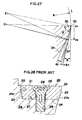
- a flank surface 31f of Fig. 27 when the flank angle ⁇ in the vicinity of the cutting edge 22 is set substantially equal to the arc-shaped flank surface 31r, in an initial stage where the cutting edge 30 is not worn, a gap avoiding interference with the material to be cut can be certainly maintained.
- the flank angle of the cutting edge 30 becomes smaller according to wearing.
- wearing of the cutting edge 30 is progressed to a position V 2
- the flank angle ⁇ r of the arc-shaped flank surface 31r becomes extremely small to make it difficult to maintain sufficient gap for avoiding interference.
- the tip causes interference with the material to be cut, to make it impossible to continue cutting work.
- the throw-away tip 20 is formed flank surfaces 23, 23 along cutting edges 22, 22 on both side edges of the rake surface 21 into convex hemisphere shape, and a screw insertion hole 25 extending from the rake surface 21 to a bottom surface 24 is formed.
- the tip 1s rigidly fixed on the cutter body 26 by fitting into a recessed tip seat 27 constituted of a concave hemisphere side surface 27a and bottom surface provided in the cutter body 26 and threadingly engaging a mounting screw 28 into a threaded hole 29 in the bottom surface 27b of the tip seat 27 through the screw insertion hole 25.
- a milling cutter including the throw-away type cut in addition to superior cutting ability, it has been required to achieve high strength and durability of the edge portion for use in high load cutting.
- the tip by employing the tip with a tip breaker, it becomes possible to set the radial rake angle at positive angle in the high axis condition.
- an overhang of the tip from the cutter body becomes large and a wedge angle of the edge portion becomes small to significantly lower strength of the edge portion of the tip per se and thus to make it meaningless to provide higher rigidity on the side of the cutter body by positioning the axis of the cutter higher.
- the flank angle can be greater than a proper angle to make it difficult to uniformly set the flank angle over the entire length of the edge.
- the present invention has been worked out in view of the problems set forth above. Therefore, it is an object of the present invention to provide a throw-away tip which can set both of an axial rake angle and a radial rake angle are large positive angle as installed on a cutter to certainly provide superior cutting ability, also can be set a strength of a cutting edge and fixing strength onto a cutter body high, and permits making a rigidity on the side of the cutter body in a condition maintaining superior cutting ability even when it is mounted on the cutter body in high axis position, and thus is superior in practical use.
- Another object of the present invention is to provide means for facilitating production of the throw-away tip set forth above.
- a further object of the present invention is to provide a throw-away type cutter which can achieve superior cutting ability and also achieves good adaptability and durability in high load cutting.
- a throw-away tip having a cutting surface of parallelogramic shape in plan view and a screw insertion hole extending from the cutting surface to a bottom surface on the opposite side of the cutting surface
- a contour line of the cutting edge may form a curved line moderately bulging in an extension direction of the flank surface from a straight line connecting the base portion side and the cutting edge portion side.
- the convex arc-shaped surface in the flank surface may be consisted of a peripheral surface of a cylinder having an axis intersecting with a tilted flat surface including the tilted surface in the cutting surface at an acute angle less than or equal to 45°, and the contour of the cutting edge forms an elliptic arc as an intersection line between the peripheral surface of the cylinder and the tilted flat surface.
- the contour line forming elliptic arc of the cutting edge may be expressed with taking a mid point of the line ab connecting both ends thereof as a point m, the direction of the line ab as X-axis, a direction connecting the point m and the mid point n of the contour line as Y-axis, a length of the line ab is j, a radius of the cylinder ⁇ forming the convex arc-shaped surface of the flank surface as k, a leg f the perpendicular line extended from the point m to the axis ⁇ of the cylinder ⁇ as m', an angle formed by the perpendicular line mm' and the titled flat surface S including the contour as ⁇ , and an intersection angle between the titled flat surface S and the axis ⁇ of the cylinder ⁇ as ⁇ , by the following expression: [Ycos ⁇ + ⁇ k 2 -(j 2 sin 2 ⁇ /4) 1/2 ⁇ ] 2 +(Xsin ⁇ -Ysin ⁇ cos ⁇
- the flank surface may be constituted of the convex arc-shaped surface over the entire length from the cutting edge portion to the base portion.
- the flank surface may be constituted of a first flank surface of the convex arc-shaped surface and located on the side of the cutting edge portion, a second flank surface inclined toward the side of the base portion than the first flank surface and stepped down from the first flank via the first flank surface.
- the flank surface may be further constituted of a third flank surface inclined toward the base portion than the second flank surface, and the first flank surface and the third flank surface may form a common convex arc-shaped surface.
- the step between the first and second flank surfaces may have a height in a range of 0.1 to 0.8 mm.
- the second flank surface may be a flat surface angled with respect to the bottom surface of the tip within an angular range of 90 to 101°.
- a production method for a throw-away tip having a cutting surface of parallelogramic shape in plan view and a screw insertion hole extending from the cutting surface to a bottom surface on the opposite side of the cutting surface, the cutting edge being so tilted as to place a height from a position of the bottom surface of the tip higher on the side of a cutting edge portion than that on the side of a base portion for forming a tilted surface descending from the cutting edge portion to a center portion, and flank surfaces on side surfaces along the cutting edge portion being convex arc-shaped surface bulging outwardly from a perpendicular line extended from a peak of the cutting edge to the bottom surface position of the tip on the side of the cutting edge portion of the cutting edge, at least on the side of the cutting edge portion, and continuously and gradually inclined toward inside of the tip from the perpendicular line from the side of the cutting edge portion to the side of the base portion, comprising the steps of:
- the raw material of the tip may be fixed on a rotary shaft, and each of the side surfaces to be the flank surfaces being ground by cylindrical grinding by contacting a grinding tool onto the raw material of the tip with rotating the rotary shaft.
- a throw-away type cutter on which a throw-away tip is fixed by means of a mounting screw, which throw-away tip having a cutting surface of parallelogramic shape in plan view and a screw insertion hole extending from the cutting surface to a bottom surface on the opposite side of the cutting surface, the cutting edge being so tilted as to place a height from a position of the bottom surface of the tip higher on the side of a cutting edge portion than that on the side of a base portion for forming a tilted surface descending from the cutting edge portion to a center portion, and flank surfaces on side surfaces along the cutting edge portion being convex arc-shaped surface bulging outwardly from a perpendicular line extended from a peak of the cutting edge to the bottom surface position of the tip on the side of the cutting edge portion of the cutting edge, at least on the side of the cutting edge portion, and continuously and gradually inclined toward inside of the tip from the perpendicular line from the side of the cutting edge portion to the side of the base portion,
- the flank surface may be constituted of a first flank surface of the convex arc-shaped surface and located on the side of the cutting edge portion, a second flank surface inclined toward the side of the base portion than the first flank surface and stepped down from the first flank via the first flank surface, and a side surface of a tip seat formed in the cutter body may include an upper side surface opposing with the first flank surface in spaced apart relationship with the latter and a flat lower side surface tightly abutting with the second flank surface.
- the first embodiment of a throw-away tip according to the first aspect of the present invention has a screw insertion hole 4 extending from a parallelogramic cutting or rake surface 2 to a bottom surface 3. Side edges of the cutting surface 2 form cutting edges 5.
- the cutting edge 5 is titled so that a height from a position of the bottom surface 3 of the tip on the side of the cutting edge portion 5a is higher than that on the side of the base portion 5b.
- On the cutting surface 3, a titled surface 2a of descending gradient from the cutting edge 5 to the center side of the tip 1 is formed.
- Flank surfaces 6 on the side of a side surface extending along the cutting edge 5 are bulged outwardly at least one the side of the cutting edge 5 from a perpendicular line p extended from a peak of the edge to a position on the bottom surface 3 of the tip, and are formed into convex arc-shaped surfaces continuous in a form gradually tiling toward inside of the tip from the foregoing perpendicular line p from the side of the cutting edge portion 5a to the side of the base portion 5b.
- each cutting edge 5 is ascendingly tilted toward the side of the cutting edge portion 5a. Also, the descending tilting surface 2a descending from the cutting tip 1 to the center side of the tip 1s provided. Since the cutting tip 1 per se has a positive axial rake angle and a radial rake angle, an axial rake angle ⁇ and a radial rake angle ⁇ as mounted on the cutter body 10 can be set at large positive angles. On the other hand, since convex arc-shaped surface is formed at least on the side of the cutting edge 5 of the flank surface 6, a flank angle ⁇ in a condition mounted on the cutter body 10 can be made small.
- a large wedge angle q of the cutting edge 5 can be certainly maintained.
- a force to pushing an inner portion of the tip away from the tip seat 11 is exerted on the outer side cutting edge 5 during cutting as a reaction of the cutting load in a tangential direction.
- the flank surface is formed into the convex arc-shaped configuration to make a distance D 1 between the upper side position of the flank surface 6 contacting with the tip seat 11 and the cutting edge 5 becomes shorter than a distance D 2 on the lower side position, the force pushing the tip away from the tip seat 11 is borne by the cutter body 10 at the contacting portion of a second flank surface 6b. Therefore, a self-holding force is provided for the tip 1 as mounted on the cutter body 10.
- the tip 1 is mounted in a back metal portion 10a of the cutter body 10 at high axis position, namely, even when a tip mounting position is set at high position in a radial direction r of the cutter body 10 parallel to the bottom surface 3 of the tip, the flank angle ⁇ can be set a roper angular range (6 to 8°). Also, an overhang amount of the cutting edge 5 from the cutter body 10 can be restricted to be minimum.
- the convex arc-shaped surface of the flank surface 6 is gradually tilted inwardly of the tip from the cutting edge portion 5a side to the base portion 5b side. Therefore, the bottom surface 13 of the-tip seat 11 of the cutter body 10 has the axial rake angle. Accordingly, while the tip 1s arranged at torsional position with respect to the cutter body 10, substantially equal flank angle ⁇ can be set over the entire length from the cutting edge portion 5a to the base portion of the cutting edge 5.
- the contour line of the cutting edge 5 forms a curve moderately bulging in a direction of extension of the flank surface 6 than the straight line ab connecting the cutting edge portion 5a side and the base portion 5b side.
- the convex arc-shaped surface in the flank surface 6 is constructed with a peripheral surface of a cylinder ⁇ having an axis ⁇ intersecting with the flat tilted surface S including the titled surface 2a in the cutting surface 2 at an acute angle less than or equal to 45°.
- the convex arc-shaped surface of the flank surface 6 can be easily formed by cylindrical grinding.
- the contour line forming elliptic arc of the cutting edge 5 may be expressed with taking a mid point of the line ab connecting both ends thereof as a point m, the direction of the line ab as X-axis, a direction connecting the point m and the mid point n of the contour line as Y-axis, a length of the line ab is j, a radius of the cylinder ⁇ forming the convex arc-shaped surface of the flank surface 6 as k, a leg f the perpendicular line extended from the point m to the axis ⁇ of the cylinder ⁇ as m', an angle formed by the perpendicular line mm' and the titled flat surface S including the contour as ⁇ , and an intersection angle between the titled flat surface S and the axis ⁇ of the cylinder ⁇ as ⁇ , by the following expression: [Ycos ⁇ + ⁇ k 2 -(j 2 sin 2 ⁇ /4) 1/2 ⁇ ] 2 +(Xsin ⁇ -Y
- the radius k of the cylinder ⁇ forming the convex arc-shaped surface in the flank surface 6 can be set to be equal to or greater than a radius R of cutting when the throw-away tip 1 is installed on the cutter body 10.
- a difference of degree of projection in the radial direction of the cutter of the base portion 5b side and the cutting edge portion 5a side versus the center portion of the cutting edge 5 becomes small.
- an overhang h of the overall tip 1 from the cutter body 10 becomes small.
- the flank surface 6 is formed into the convex arc-shaped surface over the entire length from the cutting edge 5 to the bottom portion. Therefore, the shape of the tip can be simplified.
- flank surface 6 is consisted of a first flank surface 6a on the side of the cutting edge 5 which is formed into the convex arc-shaped surface, and a flat second flank surface 6b located on the side of the bottom than the first flank surface 6a and at the stepped down position via a step 7 from the first flank surface 6a.
- the tip 1s mounted on the cutter body 10 by establishing contact of the flat surfaces with taking the flat second flank surface 6b as the contact surface with the tip seat 11, the position of the tip relative to the tip seat 11 can be restricted. Therefore, the tip can be stably fixed on the cutter body 10. Also, by the step 7, the gradient of the second flank surface 6b can be made smaller. Therefore, by setting the distance D 1 between the upper side of the second flank surface 6b and the cutting edge 5 shorter than the distance D 2 between the lower side of the second flank surface 6b and the cutting edge, greater self holding force can be obtained.
- the machining allowance is ground off by the grinding process to finish the first flank surface 6a of the convex arc-shaped configuration. Since the flat second flank surface 6b can be formed by press, grinding process can be performed with taking the second flank surface 6a as a reference of positioning in the tip width direction.
- the flank surface 6 is consisted of the first flank surface 6a and the second flank surface 6b constructed as set forth above, and in addition, a third flank surface 6c located at further bottom side of the second flank surface 6b, and the first flank surface 6a and the third flank surface 6c forms a common convex arc-shaped surface.
- a boundary portion between the bottom surface 3 and the flank surface 6 is chamfered by the third flank surface 6c. Therefore, it becomes unnecessary to provide chamfer portion for avoiding interference with the edge portion of the tip at the corner portion 15 between the side surface 12 and the bottom surface 13 of the tip seat 11 of the cutter body 10.
- a polishing process in the production of the tip 1t becomes possible to finish the first flank surface 6a and the third flank surface 6b into the convex arc-shaped surface by simultaneously grinding away the machining allowance.
- the step 7 between the firs flank surface 6a and the second flank surface 6b has a height of 0.1 to 0.8 mm to achieve the foregoing effect certainly. Furthermore, by setting the height of the step 7 within the range set forth above, it becomes possible to avoid possibility that the overhang h of the cutting edge 5 from the cutter body becomes excessive.
- the second flank surface 6b in the throw-away tip 1 is formed into a flat surface forming an angle ⁇ within a range of 90 to 101° with respect to the bottom surface of the tip 3.
- the tip upon installation of the tip onto the cutter body 10, with taking the flat second flank surface 6b as the contact surface, the tip can be positioned and retained with respect to the tip seat 11 by establishing flat surface contact with the tip seat 11.
- the tip can be stably fixed on the cutter body 10.
- excessive overhang of the cutting edge 5 from the cutter body 10 can be successfully avoided.
- contact with the tip seat 11 becomes a taper contact.
- the bottom surface 3 is contacted with the bottom surface portion 13 of the tip seat 3 under pressure to tightly or firmly fit the second flank surface 6b onto the side surface 12b of the tip seat 11 so that the tip can be rigidly fitted in further stably fixed condition.
- Each of the both side surfaces 60 to be formed into the flank surface of the raw material 1a of the tip 1s subject to cylindrical grinding taking the axis ⁇ intersecting with the tilted surface S including the tilted surface 2a at the acute angle of less than or equal to 45°, as the center, the throw-away tip having the convex arc-shaped flank surface 6 set forth above can be obtained.
- the convex arc-shaped surface serving as the flank surface 6 can be formed by simple cylindrical grinding, namely by contacting the side surface 60 with the grinding tool from the side with rotating the tip, or by contacting the side surface with the side surface 60 with causing orbital motion of the grinding tool.
- cylindrical grinding is performed by fixing the raw material 1a of the tip on a rotary shaft, contacting the grinding tool from the side with rotating the rotary shaft to form each side surface 60 to be the flank surface 6 of the raw material 1a of the tip 1n this case, the raw material 1a of the tip 1s mounted on the rotary shaft substantially similar condition as mounting on the cutter body 10. Then, the convex arc-shaped flank surface 6 can be easily formed by simply contacting the grinding tool onto the side surface 60 from the side portion with rotating the rotary shaft.
- a throw-away type cutter according to the present invention is constructed by fixing the throw-away tip according to the present invention set forth above by the mounting screw on the tip seat 11 formed in the cutter body 10.
- the throw-away tip 1s provided both of the axial rake angle ⁇ as the cutting angle in the axial direction and the radial rake angle ⁇ as the cutting angle in the radial direction at positive angles.
- the flank surface 6 on the side to be ground is rotated from a condition where the flank angle ⁇ along the cutting periphery L talking the axial center O of the cutter body 10 as a center is zero, in a direction to move the flank surface 6 away from the cutting periphery L with taking both ends of the contour of the cutting edge on the side to be ground as a fulcrum to certainly provide the flank angle ⁇ .
- the axial rake angle ⁇ and the radial rake angle ⁇ can be set at large positive angle to form at least the flank surface 6 on the side of the cutting edge 5 into convex arc-shaped configuration. Therefore, the flank angle ⁇ can be small to certainly maintain the wedge angle q of the cutting edge sufficiently large. Also, by arrangement attitude of the tip, the flank angle ⁇ becomes substantially uniform over the entire length of the cutting edge 5.
- the throw-away tip 1 constructed set forth above is employed.
- the side surface portion 12 of the tip seat 11 of the cutter body 10 is consisted of an upper side surface 12a opposing with a the first flank surface 6a with maintaining a gap therebetween and a flat lower side surface 12b tightly abutting with the second flank surface 6b.
- the side surface portion 12 of the tip seat 11 established with flat surface contact wit the second flank surface 6b of the tip 1.
- the tip 1 can be can be stably and firmly fixed to achieve superior durability withstanding for high load cutting process and high cutting precision.
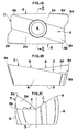
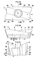
- Fig. 1A to Fig. 3C show the first embodiment of the throw-away tip
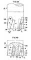
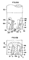
- Fig. 4A to Fig. 6 show the throw-away type cutter, in which the firs embodiment of the tip is installed
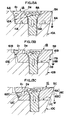
- Fig. 7A to Fig. 9C show the second embodiment of the throw-away tip
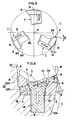
- Fig. 10A to Fig. 12 show the throw-away type cutter employing the second embodiment of the tip.
- the first embodiment of the throw-away tip 1 shown in Figs. 1A to 3C forms cutting edges 5 on both of the curved longitudinal side edges of a cutting or rake surface 2 formed into substantially parallelogramic shape in plan view and has a screw insertion hole 4 extending from the center portion of the cutting surface 2 to the bottom surface 3 on the opposite side. Then, each cutting edge 5 is tilted so that the height from the position of the bottom surface 3 of the tip on the side of the cutting edge 5a is higher than that on the side of the base portion 5b. On the other hand, on the cutting surface 2, the tilted surfaces 2a descending from the cutting edges 5 on both sides to the center side of the tip are formed. The center portion 2a of the cutting surface 2 is formed into flat.
- the tilted surfaces 2a may be formed into slightly curved surface other than the flat surface, as a matter of course.
- the tip 1 is used as the cutting edge of the cutter per one side of the cutting edges 5 by turning over 180°.
- overall tip 1 is formed symmetric about the center line of the screw insertion hole as the axis of symmetry.
- the cutting edge portions 5a and the base portions 5b of both cutting edges 5 are arranged in diagonal direction.
- the screw insertion hole 4 is constituted of a large diameter upper portion 4a, an intermediate portion 4b of reduced diameter with a peripheral surface of curved convex shape, and a small diameter lower portion 4c.
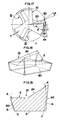
- the flank surfaces 6 on both sides as side surfaces along respective cutting edges 5 are formed into the convex arc-shaped surface extending from the cutting edges 5 to the bottom portion.
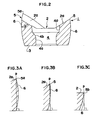
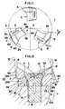
- the convex arc-shaped surface are shown in Figs. 3A to 3C, in which Fig. 3A shows the section of the cutting edge portion 5a, Fig. 3B shows the section of the intermediate portion and Fig. 3C shows the section of the base portion 5b.
- the convex arc-shaped surface is bulged outwardly from the perpendicular line p extended from the peak of the edge to the bottom of the tip and is continuous in a form tilted toward inside of the tip from the perpendicular line p.
- the tilted surface 2a of the cutting surface 2 is set to increase the width from the base portion 5b of the cutting edge 5 to the cutting edge portion 5a. Over the entire length of the cutting edge 5, substantially equal wedge angle q (see Fig. 2) is provided.
- the contour line of the cutting edge 5 becomes an intersecting line between the flank surface 6 of the convex arc-shaped surface and the tilted surface 2a as a plane surface of the cutting surface 2, which is a curved line moderately bulging toward a direction of extension of the flank surface 6 from the straight line ab connecting the side of the cutting edge portion 5a and the side of the base portion 5b.
- the curved line of the cutting edge 5 becomes an elliptic arc shape by forming the convex arc-shaped surface in the flank surface 6 with a cylindrical peripheral surface having an axis intersecting with the planar surface including the tilted angle 2a in the cutting surface 2 at acute angle less than or equal to 45°, by the tip production method which will be discussed later. As shown in Figs.
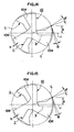
- the throw-away type cutter 10 installed with the first embodiment of the throw-away type 1 is formed with back metal portions 10a arranged radially in three directions with a phase difference of 120° about the axial center portion O by providing cut-out portions 10b at circumferential three portions on the tip end side.
- pocket form tip seats 11 are defined by the side surface portions 12 and the bottom surface portions 13. Then, in each tip seat 11, the throw-away tip 1 is fixed by means of the mounting screw 8 in a position slightly projecting the cutting edge 5 on one side outwardly from the outer periphery of the cutter body 10.
- Each tip seat 11 has the bottom surface tilted with respect to the axial direction of the cutter body 10 so as to provide the axial rake angle for the tip. Since the tip 1 per se is formed into a shape having the axial rake angle by the cutting edge 5 tilted to be higher on the side of the cutting edge portion 5a, the axial rake angle ⁇ of the cutting edge 5 in the condition mounted in the cutter body 10 is large positive angle as shown in Fig. 4A. On the other hand, as shown in Fig. 5, since the tip 1 has descending gradient from the cutting edge 5 toward the center of the cutting surface, the radial rake angle ⁇ is also large positive angle.
- flank surface 6 of the tip bulges outwardly on the side of the cutting edge portion 5a of the cutting edge 5 to form the convex arc-shaped to be gradually tilted toward inside of the tip to the side of the base portion 5b. Therefore, the flank angle ⁇ is held substantially constant appropriate small angle (6 to 8°) over the entire length from the side of the cutting edge portion 5a to the base portion 5b.
- the throw-away tip 1 in the throw-away type cutter is fixed on the cutter body 10 by tightening the mounting screw 8 into the threaded hole 14 formed in the bottom surface 13 of the tip seat 11 through the screw insertion hole 4.
- the side surface portion of the tip seat 11 is in two-step form.
- the upper side surface 12a is placed away with respect to the upper side of the flank surface 6 of the tip 1.
- the lower side surface 12b is formed into concave arc-shaped configuration for tightly fitted with the lower portion of the flank surface 6.
- the corner portion 15 between the side surface portion 12 and the bottom surface portion 13 is formed into a cut-away portion for avoiding interference with the edge portion of the tip 1.
- the second embodiment of the throw-away tip 1 shown in Figs. 7A to 9C is similar to the first embodiment of the tip 1 except for the flank surfaces 6 on both sides.
- the common portions with the first embodiment will be represented by the same reference numerals and the detailed description thereof will be neglected in order to keep the disclosure simple enough by avoiding redundant discussion for facilitating clear understanding of the present invention.
- the flank surface 6 of the tip is constituted of a first flank surface 6a formed into convex arc-shape on the side of the cutting edge 5, a flat second flank surface 6b stepped down from the first flank surface 6a via the step 7, and a third flank surface 6c located at a position further inclined toward the bottom side than the second flank surface 6b.
- the first flank surface 6a and the third flank surface 6c form a common convex arc-shaped surface as connected by a phantom line shown in the outside of the second flank surface in Fig. 7C and Fig. 8.
- the first flank surface 6a is bulged outwardly from the perpendicular line p extended from the peak of the edge to the position of the bottom of the tip on the side of the cutting edge portion 5a of the cutting edge 5, as shown in Figs. 9A to 9C, in which Fig. 9A shows the section on the side of the cutting edge portion 5a, Fig. 5B shows the section on the intermediate portion and Fig. 5C shows the section on the side of the base portion 5b and is formed into the convex arc-shape continuous to gradually tilt toward inside of the tip from the perpendicular line p extended from the side of the cutting edge portion 5a to the side of the base portion 5b.
- the curved line of the cutting edge 5 becomes elliptic arc-shape by forming the convex arc-shaped surface in the flank surface with the cylindrical peripheral surface having the axis intersecting with the tilted flat surface including the tilted surface 2a in the cutting surface 2 at an acute angle less than or equal to 45° by the following tip production method.
- height difference between the lower edge of the first flank surface 6a and the upper edge of the second flank surface 6b by the step 7, is preferably set within a range of 0.1 to 0.8 mm.
- the angle ⁇ (see Fig. 8) between the second flank surface 6b and the bottom surface 3 of the tip is preferred to be in a range of 90 to 101°.
- the substantially the same wedge angle q (see Fig. 8) is provided over the entire length of the cutting edge 5.
- the throw-away type cutter installed with the foregoing second embodiment of the throw-away tip 1 is, similarly to the cutter installed with the first embodiment of the tip, has back metal portions 10a arranged radially in three directions by forming the cut-outs 10b at three circumferential positions on the tip end side.
- the throw-away tip 1 is fixed by means of the mounting screw 8 in a condition where the one of the cutting edges 5 is slightly bulged from the outer periphery of the cutter body 10.
- each tip seat 11 is titled with respect to the axial direction of the cutter body 10 for providing the axial rake angle. Since the tip per se has the axial rake angle by the cutting edge 5 tilted to be higher on the side of the cutting edge 5a, the axial rake angle ⁇ of the cutting edge 5 in the condition mounted in the cutter body 10 is large positive angle as shown in Fig. 10A. On the other hand, as shown in Fig. 11, since the tip 1 has descending gradient from the cutting edge 5 toward the center of the cutting surface, the radial rake angle ⁇ is also large positive angle.
- the first flank surface 6a of the tip 1 bulges outwardly on the side of the cutting edge portion 5a of the cutting edge 5 to form the convex arc-shaped to be gradually tilted toward inside of the tip to the side of the base portion 5b. Therefore, the flank angle ⁇ is held substantially constant appropriate small angle (6 to 8°) over the entire length from the side of the cutting edge portion 5a to the base portion 5b.
- the throw-away tip 1 is fixed on the cutter body 10 by tightening the mounting screw 8 into the threaded hole 14 formed in the bottom surface 13 of the tip seat 11 through the screw insertion hole 4.
- the side surface portion of the tip seat 11 is in two-step form.
- the upper side surface 12a is placed away with respect to the upper side of the flank surface 6 of the tip 1.
- the lower side surface 12b is tightly fitted with the lower portion of the flank surface 6.
- a gap is formed between the third flank surface 6c.
- the first or second embodiment of the throw-away tip can provide the axial rake angle ⁇ and the radial rake angle ⁇ at large positive angle to make cutting resistance small to achieve superior cutting ability.
- the flank surface 6 of the tip 1 is formed into the convex arc-shaped surface on the side of the cutting edge portion 5a (overall flank surface 6 in the first embodiment and the first flank surface 6a in the second embodiment), the flank angle ⁇ can be maintained within the proper small angular range of 6 to 8° even when wearing of the cutting edge 5 is progressed to continue stable cutting.
- the wedge angle q of the cutting edge 5 is large to achieve superior strength of the cutting edge, high durability of the cutting edge can be achieved.
- the distance D 1 between the upper side of the flank surface 6 contacting with the lower side surface 12b of the tip seat 11 is shorter than the distance D 2 between the lower side of the flank surface and the cutting edge
- the force to lift the tip 1 away from the tip seat is borne by the cutter body 10 at the contact portion between the lower side surface 12b of the tip seat 11 and the tip.
- the tip 1 may have self-holding force to hardly exert the reactive force to the mounting screw 8 to achieve quite high durability for the cutting load.
- the distances D 1 and D 2 shown by the phantom lines represent the same distance at the position of the cutting edge portion 5b.
- the distances D 1 and D 2 between the cutting edge 5 on the side of cutting in the throw-away tip 1 and upper and lower positions of the contact portion with respect to the side surface portion 12 of the tip seat 11 becomes D 1 ⁇ D 2 .
- convex arc-shaped surface of the flank surface 6 is bulged outwardly in the lower portion than the peak of the cutting edge on the side of the cutting edge portion 5a of the cutting edge 5 (the first flank surface 6a of the second embodiment to achieve large self-holding force on the tip 1.
- the step 7 is provided between the first flank surface 6a and the second flank surface 6b to make it possible to reduce the gradient of the second flank surface 6b in surface contact with the surface of the tip seat 11.
- a difference between the distances D 1 and D 2 can be set large.
- the cutting edge portion 5B may propagate to the position to the step 7B to make it impossible to position and restrict the tip once breakage is caused to use the tip in the reversed position.
- the cutting edge portion 5B may propagate to the position to the step 7B to make it impossible to position and restrict the tip once breakage is caused to use the tip in the reversed position.
- the deposition to the titled flat surface portion 61B due to deposition to the titled flat surface portion 61B, fluctuation of the cutting edge position upon using with reversal and unstability of the mounting position can be caused.
- the positioning the restricting surface is formed by forming the flank surface 6C of the throw-away tip 1C with a moderately tilted portion 61C on the side of the cutting edge portion 5C and a steep tilted portion 62C on the side of the bottom portion, is established by contacting the steep tilted position 62C on the bottom side onto the side surface portion 12C of the tip seat 11C in the cutter body 10, no problem will be caused in positioning and restricting upon reversal due to breakage of the cutting edge portion 5C and deposition.
- the cutting edge is mounted with locating the axis of the cutting edge at high position. As shown in Fig. 14 (installing the tip of the first embodiment) and in Fig.
- a height u of the cutting edge 5 with taking a radial direction r parallel to the bottom surface of the tip 1 of the cutter body 10 is set high and the flank angle ⁇ is set at a proper angular range (6 to 8°), the rigidity of the cutter body 10 can be increased by increasing the thickness of the back metal portion 10a and the diameter of the radial center portion. Furthermore, the overhang of the tip can be restricted minimum.
- the wedge angle q per se can be large.
- the tip 1 is set at high axis position as shown in Fig. 16A, if the flank angle ⁇ 2 on the base portion side is certainly provided (frequently greater than or equal to 10°), and the flank angle ⁇ 1 on the cutting edge side becomes extremely large (possibly exceed 20°). Furthermore, overhang h becomes large to lower strength of the edge portion.
- the radial rake angle ⁇ becomes large negative angle to significantly increase the cutting resistance, increasing of rigidity of the cutter body 10 by installing the tip at high axis position becomes meaningless.
- the tip breaker (a shape where both sides along the cutting edge 5D of the cutting surface 2D are risen) as a tip 1D shown in Fig. 17, to set the radial rake angle ⁇ at the high axis position at positive angle, if the flank angle ⁇ 2 on the base portion side is certainly provided (frequently greater than or equal to 10°), and the flank angle ⁇ 1 on the cutting edge side becomes extremely large (possibly exceed 20°). Furthermore, overhang h becomes large to lower strength of the edge portion. Also, since the wedge angle q of the cutting edge portion becomes small to extremely weaken the strength of the cutting edge portion to cancel effect of increasing of rigidity of the cutter body 10 by high axis position.
- the throw-away type cutter 10 has small cutting resistance, small magnitude in vibration or so forth in cutting, to achieve smooth cut, to exhibit high adaptability of the strength of the cutting edge for high load cutting and to achieve superior durability for long life, and thus can provide quite high total performance.
- the flat second flank surface 6b of the tip 1 is taken as a restricting surface to establish surface contact with the lower side surface of the tip seat 11 to establish stable mounting condition without causing fear of play or so forth during cutting.
- the mounting screw 8 is threadingly tightened into the thread hole 14 of the tip seat 11 upon mounting, strong taper contact between the second flank surface 6b and the lower side surface 12b of the tip seat 11 can be contacted under pressure, quite firm fixing condition can be established.
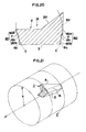
- a raw material 1a of the tip is prepared by press molding of a powder state cemented material under heating condition to have tilted surfaces 2a on both sides of the cutting surface 2 and a machining allowance in a portion to be the flank surface 6. After sintering the press molded raw material, the flank surface 6 is formed into the convex arc-shaped surface by grinding process.
- a raw material 1a of the tip in which entire length of both side surfaces 60 to be the flank surface 6 is formed into flat surface, is employed.
- the raw material of the second embodiment of the tip as shown in Fig. 20, the raw material 1a of the tip having both side surfaces 60 of stepped two level form consisted of a planar surface 60a providing the machining allowance in a region corresponding to the first flank surface 6a, and a planar surface 60b providing the machining allowance in the third flank surface in a form where the flat second flank surface 6b is extended to the bottom surface 3.
- both side surfaces 60 of the raw material 1a of the tip is ground in arc-shape up to the cut line C shown by the phantom line of Figs. 19 and 20.
- the second flank surface 6b in the second embodiment of the tip 1 is formed in a region of the planar surface 6b left as non-ground portion.
- the intersecting angle of the tilted flat surface and the axis corresponds to the axial rake angle ⁇ upon installation to the cutter body 10.
- the cutting edge is mounted on the cutter body in an excessively tilted form to make the cutting width short in the direction of the cutter axis to make the side of the cutting edge portion 5a of the cutting edge thinner to easily cause breakage.
- the raw material 1a of the tip is mounted on a rotary shaft to be a supporting base body in an arrangement substantially similar to a condition of installation of the cutter body 10, and, with rotating the rotary shaft, a cutting tool, such as a bite or o forth is contacted from the side portion for form the convex arc-shaped flank surface 6 by cutting one of the side surface 60, and by mounting the raw material 1a of the tip on the rotary shaft in the position reversed over 180°, the other side surface 60 is cut in similar manner to form the flank surface 6.
- a cutting tool such as a bite or o forth
- the tip is mounted on the tip seat by means of the mounting screw 8, the raw material 1a of the tip is fixed on the rotary shaft in a condition where the one of the side surface 60 of the entire length is extended outwardly beyond the machining allowance from the outer periphery of the rotary shaft.
- Fig. 21 shows a relationship of arrangement of the grinding cylinder ⁇ upon termination of grinding and the tip 1 in cylindrical grinding. It should be noted that, in order to facilitate understanding, the first embodiment of the tip 1 is illustrated in a further simplified form.
- the hatching of the broken line shows a section of the tip along the diametrical direction f the grinding cylinder ⁇ .
- the reference sing k represents a radius of the grinding cylinder ⁇ and ⁇ shows the axis of the grinding cylinder ⁇ .
- the throw-away tip 1 obtained by forming the flank surfaces 6 by grinding process is, in the condition installed on the cutter body 10, is pivoted from a condition where the flank surface 6 on the cutting side extending along the grinding cylinder L centered at the axis O of the cutter body 10 t have no flank angle ⁇ to move the flank surface 6 away from the grinding cylinder L with taking both ends of the contour of the cutting edge 5 on the cutting side as fulcrums to certainly provide the flank angle ⁇ .
- the cutter body 10 having the tip seat 11 to be placed in the arrangement condition shown by solid line in Fig. 22 may be employed. Therefore, the tip seat 11 is desired to be a size and shape where the end edge of the bottom surface 3 of the flank surface 6 of the tip 1 installed in the foregoing arrangement condition and the outer end edge of the back metal portion 10a are consistent. It should be noted that, in the drawing, the reference sign i is a radius of the cutter body 10 (back metal portion 10a).
- the flank angle ⁇ is certainly provided in a form translated the attitude similarly to the foregoing even when k ⁇ R.
- the condition the flank surface 6 of the tip 1 extends along the cutting circumferential periphery L of the cutter body 10 represents the state where the small circle of the grinding cylinder ⁇ internally contacts with the large circle of the cutting circumferential periphery L, in which the flank surface 6 is placed away from the cutting circumferential periphery L at greater magnitude at closer position to the bottom surface 3.
- flank angle ⁇ is zero to tightly contact in the vicinity of the cutting edge 5 to be placed in a condition impossible to grind, in this arrangement, only by placing the tip in the attitude pivoted about both ends of the cutting edge 5 as fulcrum, the flank angle ⁇ is certainly provided.
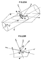
- Fig. 23A shows a relationship between the tilted flat surface S and the grinding cylinder ⁇ forming the flank surface 6 with taking the tilted flat surface including the tilted surface 2a in the cutting surface of the tip 1 being the tilted flat surface S.
- Fig. 23B is an enlarged illustration of the portion of the flank surface 6 on one side of the tip 1 in Fig. 23A.
- the intersection between the tilted flat surface S and the peripheral surface of the grinding cylinder ⁇ becomes elliptic. Therefore, the contour of the cutting edge 5 becomes elliptic arc-shape.
- a method for deriving the expression of the curve of the contour will be discussed.
- both ends of the contour line of the cutting edge 5 are a and b (the end on the side of the cutting edge portion 5a is taken is a and the end on the side of the base portion 5b is taken as b), a direction of a line ab connecting the points a and b by straight line is x-axis, a mid point of the line ab is an origin m, an intermediate point of the contour line is point n, a leg of the perpendicular line extended downwardly from the axis ⁇ of the grinding cylinder ⁇ from the point m is m', a direction of the perpendicular line mm' is y-axis, a direction perpendicularly intersecting with the x-axis and y-axis through the point m is z-axis, an angle formed by the y-axis (perpendicular line mm') and the tilted flat surface S is ⁇ , an intersection angle between the tilted flat surface S
- Fig. 24A is a projected view of the flank surface 6a on the plane perpendicular to the line ab. Since the direction of line ab corresponds to x-axis, a projected surface becomes yz plane.
- the expression of the contour line of the cutting edge 5, namely the intersection line of the tilted flat surface S and the grinding cylinder ⁇ is obtained by solving the simultaneous expression (2) and (5). Since solving this simultaneous expression is difficult, coordinate conversion (x, y, z ⁇ X, Y, Z) so that the tilted flat surface S lies on the xy plane.
- Fig. 24 shows coordinate conversion.
- the foregoing equation (10) provides strict expression of the contour including the curve (ellipse). This means that Y is not even function of X and is not simple curve of the second order.
- the tilted flat surface S can be rotated about the line ab as the axis of rotation and the angle ⁇ formed by the tilted flat surface S and the y-axis is variable.
- the axial rake angle of the cutting edge 5 in the grinding cylinder ⁇ is the intersection angle ⁇ between the line ab and the axis ⁇ of the grinding cylinder ⁇ and is invariable even if the angle ⁇ is varied.
- the angle ⁇ is a parameter independent of the axial rake angle and can be remained as free parameter even when the axial rake angle is determined. This means that upon production of the tip, the range of selection of the elliptic arc of the contour line of the cutting edge becomes wide and leads to the advantageous point to be adapted to the difference of the use condition of the cutter.
- the first stage differentiation becomes - sin ⁇ cos ⁇ sin ⁇ (k 2 - d 2 ) + 2dX sin ⁇ cos ⁇ + X 2 sin 2 ⁇ cos ⁇ sin ⁇ 2(d cos ⁇ - X sin ⁇ cos ⁇ sin ⁇ ) 2
- the second stage differentiation becomes - sin 2 ⁇ d 2 cos 2 ⁇ + (k 2 - d 2 ) cos 2 ⁇ sin 2 ⁇ + 2dX sin ⁇ cos ⁇ sin ⁇ cos ⁇ (d cos ⁇ - X sin ⁇ cos ⁇ sin ⁇ ) 2
- the curve radius can be expressed by: [4(d cos ⁇ -X sin ⁇ cos ⁇ sin ⁇ ) 4 +sin 2 ⁇ cos ⁇ sin ⁇ (k 2 -d 2 )+2dX sin ⁇ cos ⁇ +X 2 sin 2 ⁇ cos ⁇ sin ⁇ 2 ] 3/2 sin 2 ⁇ d 2 cos 2 ⁇ +(k 2 -d 2 )cos 2 ⁇ sin 2 ⁇ +2dX sin ⁇ cos ⁇ sin ⁇ cos ⁇ (d cos ⁇ -X sin ⁇ cos ⁇ sin ⁇ ) 3
- the tip formed with the flank surface 6 through grinding process by means of the grinding cylinder ⁇ having a radius k is fixed in the attitude pivoted about both ends of the cutting edge 5 serving as fulcrum, namely about the line ab from the arrangement condition in the grinding cylinder ⁇ upon effecting the grinding process for forming the flank surface 6, over an angle ⁇ .
- the equation of the contour line of the cutting edge expressed by the foregoing expression (11) and the curve radius expressed by the foregoing expression (18) can be established on any point of the ellipse Q, on which the contour line forms an intersection line between the tilted flat plane S and the grinding cylinder ⁇ .
- the actual contour line of the cutting edge 5 forms a curve moderately bulging in the direction of extension of the flank surface 6 beyond the line ab connecting the cutting edge portion 5a and the base portion 5b, the elliptic arc at the position where the center portion of the contour line conversely form concave shape, is inappropriate.
- the contour line of the cutting edge 5 is inclined in the cutting direction to make the axial rake angle to be extremely large to cause the same problem as that the intersection angle between the axis ⁇ of the grinding cylinder ⁇ and the tilted flat surface S exceeds 45°.
- the tip of the present invention is fixed at the attitude pivoted inwardly from the arrangement position in the grinding cylinder ⁇ upon machining the convex arc-shaped surface of the flank surface 6 over an angle ⁇ about the line ab, with respect to the cutter body 10.
- a trace of rotation of the contour of the cutting edge 5 does not become cylindrical but becomes convex drum shape.
- conversion of attitude becomes a condition of S' by pivoting the tilted flat surface S over the angle ⁇ about the X axis to for the curve placing the intermediate point n of the contour line at a position n'.
- the contour line becomes a curve projecting in the radius direction.
- the projecting amount t of the intermediate point n' of the contour line after attitude conversion is merely 8.4 ⁇ m and is extremely smaller in comparison with the cutting radius about 10 mm. Therefore, no particular problem will be caused in cutting process by the cutter, such as the end mill.
- the radius k of the grinding cylinder ⁇ is not necessarily the same as the radius R of the cutting circumferential periphery L upon cutting process of the cutting object by means of the throw-away type cutter installed the tip set forth above.
- the R is 20 mm whereas k is 22 mm, 23 mm or 21 mm.
- the projection amount t of the center portion of the contour of the cutting edge 5 becomes small.
- the radius k of the grinding cylinder ⁇ is preferred to be equivalent to the radius R of the cutting circumferential periphery L upon cutting process by the cutter or greater.
- the flank surface 6 at least on the side of the cutting edge 5 into convex arc-shaped surface and the convex arc-shaped surface of the flank surface 6 can be formed by cylindrical grinding to satisfactorily compensate the drawback that pivoting trace of the contour line of the cutting edge 5 becomes slightly convex drum shape.
- the convex arc-shaped surface can be formed only by mounting the raw material 1a of the tip on the rotary shaft to be the holding body in the predetermined attitude and contacting the cutting tool, such as bite or so forth from the side portion with rotating the rotary shaft. Therefore, no complicate control operation is required in the grinding process to permit quite easily and stably produce the tip at high dimensional precision without causing any fluctuation.
- special curve surface processing facility investment and production cost can be reduced significantly to permit supply of the tip at low cost.
- the second flank surface 6b can be formed by press molding upon production of the raw material 1a of the tip. Therefore, upon grinding of the first flank surface 6a of the convex arc-shape by cylindrical grinding of the raw material 1a of the tip after sintering, it is advantageous to permit grinding process with taking the flat surface form second flank surface 6b as reference for positioning in the tip width direction. Furthermore, in the construction where the convex arc-shaped third flank surface 6c is provided as in the second embodiment of the tip, the third flank surface 6c chamfers the edge portion of the bottom of the tip 1. Therefore, it becomes unnecessary to provide a cut-out portion in the corner portion 15 between the side surface 12 and the bottom surface 13 of the tip seat 11 of the cutter body 10 to avoid interference with the edge portion of the tip. Thus, production of the cutter body is facilitated.
- the throw-away tip according to the present invention includes various different shaped of the edge portion on the side of the shorter edge of the cutting surface.
- the throw-away type cutter according to the present invention may be a construction, in which two or four tips 1 may be installed instead of three tips as in the cutter body 10.
- the convex arc-shaped surface in the flank surface is constructed with a peripheral surface of a cylinder having an axis intersecting with the flat tilted surface including the titled surface in the cutting surface at an acute angle, the contour line of the cutting edge becomes elliptic arc as the intersection line between the peripheral surface of the cylinder and the tilted flat surface. Therefore, the convex arc-shaped surface of the flank surface can be easily formed by cylindrical grinding.
- the contour line forming elliptic arc expressed by particular expression. Particularly for facilitating production, uniform flank angle can be set over the entire length of the cutting edge upon installation onto the cutter body. Also, upon production of the tip, since the selection range of the contour line of the cutting edge can be wide to adapt to difference of use condition of the cutter.
- the radius of the cylinder forming the convex arc-shaped surface in the flank surface can be set to be equal to or greater than a radius of cutting when the throw-away tip is installed on the cutter body.
- a difference of degree of projection in the radial direction of the cutter of the base portion side and the cutting edge portion side versus the center portion of the cutting edge becomes small.
- an overhang of the overall tip from the cutter body becomes small to increase ability of adapting to high load cutting with high strength of the cutting edge in the cutter.
- the tip having the simple shape and being easily produced can be provided.
- the tip can be firmly fixed in the stable condition on the cutter body, and in conjunction therewith, high dimensional precision and high stability of quality can be achieved in manufacturing of the tip.
- the throw-away tip may avoid necessity for forming the cut-out for avoiding interference of the edge portion of the tip to the corner portion between the side surface and the bottom surface of the tip seat in the cutter body. Thus, production of the tip can be facilitated.
- the throw-away tip can be mounted in stable condition and the overhang of the cutting edge can be minimized.
- the convex arc-shaped surface of the flank surface can be easily and precisely formed by cylindrical grinding of both side surfaces of the raw material of the tip formed by press of a super hard material and sintering thereof.
- cylindrical grinding is performed by fixing the raw material of the tip on a rotary shaft, contacting the grinding tool from the side with rotating the rotary shaft to form each side surface to be the flank surface of the raw material of the tip
- the raw material of the tip is mounted on the rotary shaft substantially similar condition as mounting on the cutter body. Then, the convex arc-shaped flank surface can be easily formed by simply contacting the grinding tool onto the side surface from the side portion with rotating the rotary shaft.
- a throw-away type cutter according to the present invention constructed by fixing the throw-away tip according to the present invention set forth above can set both of the axial rake angle and the radial rake angle at large positive angles.
- the flank angle can be small to certainly maintain the wedge angle of the cutting edge sufficiently large.
- the flank angle to achieve small vibration during cutting for small cutting resistance, smooth cut.
- the strength of the cutting edge can achieve high adaptability for high load cutting to exhibit high durability to achieve superior performance in total.
- the throw-away type cutter may achieve high holding strength and high stability of seating of the throw-away tip to withstand for cutting process under high load.
Applications Claiming Priority (2)
| Application Number | Priority Date | Filing Date | Title |
|---|---|---|---|
| JP34608897 | 1997-12-16 | ||
| JP34608897A JP4315480B2 (ja) | 1997-12-16 | 1997-12-16 | スローアウェイチップ |
Publications (3)
| Publication Number | Publication Date |
|---|---|
| EP0925863A2 true EP0925863A2 (de) | 1999-06-30 |
| EP0925863A3 EP0925863A3 (de) | 2002-01-16 |
| EP0925863B1 EP0925863B1 (de) | 2004-11-24 |
Family
ID=18381064
Family Applications (1)
| Application Number | Title | Priority Date | Filing Date |
|---|---|---|---|
| EP98116958A Expired - Lifetime EP0925863B1 (de) | 1997-12-16 | 1998-09-08 | Schneideinsatz, Herstellungsmethode und Fräser |
Country Status (3)
| Country | Link |
|---|---|
| EP (1) | EP0925863B1 (de) |
| JP (1) | JP4315480B2 (de) |
| DE (1) | DE69827753T2 (de) |
Cited By (13)
| Publication number | Priority date | Publication date | Assignee | Title |
|---|---|---|---|---|
| EP1344595A3 (de) * | 2002-03-11 | 2003-11-19 | Mitsubishi Materials Corporation | Schneideinsatz und Schneidwerkzeug |
| EP1462199A1 (de) | 2003-03-22 | 2004-09-29 | Walter Ag | Schneiplatte und Fräswerkzeug |
| WO2005065874A1 (de) * | 2003-12-23 | 2005-07-21 | EMUGE-Werk Richard Glimpel GmbH & Co. KG Fabrik für Präzisionswerkzeuge | Schneidelement und werkzeug mit wenigstens einem schneidelement |
| EP1736266A1 (de) * | 2005-06-23 | 2006-12-27 | Hartmetall-Werkzeugfabrik Paul Horn Gmbh | Schneideinsatz |
| DE10144735C5 (de) * | 2001-09-11 | 2007-01-18 | Maier Gmbh | Schneideinsätze und Rotations-Umfangsfräser mit austauschbaren Schneideinsätzen |
| WO2009121459A1 (de) * | 2008-03-31 | 2009-10-08 | Hartmetall-Werkzeugfabrik Paul Horn Gmbh | Schneidwerkzeug für spanende bearbeitung von werkstücken, sowie halter für ein schneideinsatz |
| WO2010023659A1 (en) * | 2008-08-31 | 2010-03-04 | Iscar Ltd. | Cutting tool and round double sided cutting insert therefor |
| US20110123280A1 (en) * | 2008-05-30 | 2011-05-26 | Kennametal Inc. | End Mill Cutter |
| EP2415544A1 (de) * | 2009-04-02 | 2012-02-08 | Tungaloy Corporation | Schneideinsatz und wendeschneidwerkzeug |
| US8142113B2 (en) | 2004-09-29 | 2012-03-27 | Kyocera Corporation | Throwaway insert and milling tool equipped with the same |
| DE102012104082A1 (de) * | 2012-05-09 | 2013-11-14 | Walter Ag | Wendeschneidplatte für Eckfräser |
| EP2977136A4 (de) * | 2013-03-19 | 2016-11-23 | Tungaloy Corp | Schneideinsatz und schneidwerkzeug mit auswechselbarer schneidkante |
| US10207342B2 (en) | 2013-09-11 | 2019-02-19 | Mitsubishi Hitachi Tool Engineering, Ltd. | Indexable rotary cutting tool and insert used therein |
Families Citing this family (21)
| Publication number | Priority date | Publication date | Assignee | Title |
|---|---|---|---|---|
| JP2003019617A (ja) * | 2001-07-09 | 2003-01-21 | Daishowa Seiki Co Ltd | 切削工具用インサート及び切削工具 |
| AT5969U1 (de) | 2001-12-21 | 2003-02-25 | Plansee Tizit Ag | Fräswerkzeug |
| JP4247709B2 (ja) * | 2003-05-21 | 2009-04-02 | 株式会社安川電機 | レーザ溶接装置 |
| JP4859364B2 (ja) * | 2003-11-27 | 2012-01-25 | 京セラ株式会社 | スローアウェイエンドミル |
| JP4823266B2 (ja) * | 2003-11-27 | 2011-11-24 | 京セラ株式会社 | 切削方法 |
| US7004689B2 (en) * | 2004-01-09 | 2006-02-28 | Kennametal Inc. | High-speed milling cutter and insert |
| IL160223A (en) * | 2004-02-04 | 2008-11-26 | Carol Smilovici | Double-sided cutting insert and milling cutter |
| JP4706284B2 (ja) * | 2004-04-06 | 2011-06-22 | 三菱マテリアル株式会社 | インサート着脱式転削工具 |
| JP4859494B2 (ja) * | 2005-03-31 | 2012-01-25 | 京セラ株式会社 | スローアウェイチップおよびそれを備える転削用工具 |
| JP4797462B2 (ja) * | 2005-06-24 | 2011-10-19 | 株式会社タンガロイ | 回転工具 |
| JP4983351B2 (ja) * | 2007-04-05 | 2012-07-25 | 三菱マテリアル株式会社 | 切削インサートおよびインサート着脱式転削工具 |
| JP4983352B2 (ja) * | 2007-04-05 | 2012-07-25 | 三菱マテリアル株式会社 | 切削インサートおよびインサート着脱式転削工具 |
| DE102009020373A1 (de) * | 2009-05-08 | 2010-11-11 | Kennametal Inc. | Fräser-Schneideinsatz |
| DE102010006796B4 (de) | 2010-02-04 | 2011-12-08 | Kennametal Inc. | Verfahren zur Herstellung eines Bohrers, sowie Bohrer |
| DE102010006797B4 (de) | 2010-02-04 | 2011-12-22 | Kennametal Inc. | Bohrwerkzeug |
| JP5196077B2 (ja) * | 2010-06-21 | 2013-05-15 | 株式会社タンガロイ | 切削用インサートおよび刃先交換式転削工具 |
| DE102010026271B4 (de) | 2010-07-06 | 2019-02-14 | Kennametal Inc. | Bohrwerkzeug |
| US9623495B2 (en) | 2014-10-06 | 2017-04-18 | Kennametal Inc. | Cutting insert with asymmetric cutting edge |
| JP6035697B1 (ja) * | 2015-12-24 | 2016-11-30 | 株式会社タンガロイ | 切削インサートおよび切削工具 |
| CN108673075A (zh) * | 2018-05-21 | 2018-10-19 | 哈尔滨汽轮机厂有限责任公司 | 一种三齿非工作面车刀的加工方法 |
| US11865629B2 (en) | 2021-11-04 | 2024-01-09 | Kennametal Inc. | Rotary cutting tool with high ramp angle capability |
Citations (3)
| Publication number | Priority date | Publication date | Assignee | Title |
|---|---|---|---|---|
| US5513931A (en) * | 1994-07-19 | 1996-05-07 | Valenite Inc. | Elliptical cutting insert for a milling cutting tool |
| US5556239A (en) * | 1993-10-18 | 1996-09-17 | Valenite Inc. | Positive cutting insert with compound clearance faces |
| WO1997010916A1 (en) * | 1995-09-18 | 1997-03-27 | Iscar Ltd. | Milling cutting insert |
-
1997
- 1997-12-16 JP JP34608897A patent/JP4315480B2/ja not_active Expired - Lifetime
-
1998
- 1998-09-08 DE DE69827753T patent/DE69827753T2/de not_active Expired - Lifetime
- 1998-09-08 EP EP98116958A patent/EP0925863B1/de not_active Expired - Lifetime
Patent Citations (3)
| Publication number | Priority date | Publication date | Assignee | Title |
|---|---|---|---|---|
| US5556239A (en) * | 1993-10-18 | 1996-09-17 | Valenite Inc. | Positive cutting insert with compound clearance faces |
| US5513931A (en) * | 1994-07-19 | 1996-05-07 | Valenite Inc. | Elliptical cutting insert for a milling cutting tool |
| WO1997010916A1 (en) * | 1995-09-18 | 1997-03-27 | Iscar Ltd. | Milling cutting insert |
Cited By (23)
| Publication number | Priority date | Publication date | Assignee | Title |
|---|---|---|---|---|
| DE10144735C5 (de) * | 2001-09-11 | 2007-01-18 | Maier Gmbh | Schneideinsätze und Rotations-Umfangsfräser mit austauschbaren Schneideinsätzen |
| EP1344595A3 (de) * | 2002-03-11 | 2003-11-19 | Mitsubishi Materials Corporation | Schneideinsatz und Schneidwerkzeug |
| US7014395B2 (en) | 2002-03-11 | 2006-03-21 | Mitsubishi Materials Corporation | Throwaway insert and cutting tool having throwaway insert |
| EP1462199A1 (de) | 2003-03-22 | 2004-09-29 | Walter Ag | Schneiplatte und Fräswerkzeug |
| WO2005065874A1 (de) * | 2003-12-23 | 2005-07-21 | EMUGE-Werk Richard Glimpel GmbH & Co. KG Fabrik für Präzisionswerkzeuge | Schneidelement und werkzeug mit wenigstens einem schneidelement |
| US8142113B2 (en) | 2004-09-29 | 2012-03-27 | Kyocera Corporation | Throwaway insert and milling tool equipped with the same |
| EP1736266A1 (de) * | 2005-06-23 | 2006-12-27 | Hartmetall-Werkzeugfabrik Paul Horn Gmbh | Schneideinsatz |
| WO2009121459A1 (de) * | 2008-03-31 | 2009-10-08 | Hartmetall-Werkzeugfabrik Paul Horn Gmbh | Schneidwerkzeug für spanende bearbeitung von werkstücken, sowie halter für ein schneideinsatz |
| US20110123280A1 (en) * | 2008-05-30 | 2011-05-26 | Kennametal Inc. | End Mill Cutter |
| CN102131606A (zh) * | 2008-08-31 | 2011-07-20 | 伊斯卡有限公司 | 切削工具及其圆形双面切削刀块 |
| WO2010023659A1 (en) * | 2008-08-31 | 2010-03-04 | Iscar Ltd. | Cutting tool and round double sided cutting insert therefor |
| CN103737093A (zh) * | 2008-08-31 | 2014-04-23 | 伊斯卡有限公司 | 切削工具及其圆形双面切削刀块 |
| US8206066B2 (en) | 2008-08-31 | 2012-06-26 | Iscar, Ltd. | Cutting tool and round double sided cutting insert therefor |
| CN103737093B (zh) * | 2008-08-31 | 2017-03-01 | 伊斯卡有限公司 | 切削工具及其圆形双面切削刀块 |
| USRE45845E1 (en) | 2008-08-31 | 2016-01-19 | Iscar, Ltd. | Cutting tool and round double sided cutting insert therefor |
| EP2415544A1 (de) * | 2009-04-02 | 2012-02-08 | Tungaloy Corporation | Schneideinsatz und wendeschneidwerkzeug |
| US8696263B2 (en) | 2009-04-02 | 2014-04-15 | Tungaloy Corporation | Cutting insert and cutting edge replaceable cutting tool |
| EP2415544A4 (de) * | 2009-04-02 | 2013-12-11 | Tungaloy Corp | Schneideinsatz und wendeschneidwerkzeug |
| EP3050656A1 (de) * | 2009-04-02 | 2016-08-03 | Tungaloy Corporation | Schneideinsatz und wendeschneidwerkzeug |
| DE102012104082A1 (de) * | 2012-05-09 | 2013-11-14 | Walter Ag | Wendeschneidplatte für Eckfräser |
| US9821382B2 (en) | 2012-05-09 | 2017-11-21 | Walter Ag | Indexable insert for shoulder milling cutter and shoulder milling cutter with mounting cutouts for indexable inserts |
| EP2977136A4 (de) * | 2013-03-19 | 2016-11-23 | Tungaloy Corp | Schneideinsatz und schneidwerkzeug mit auswechselbarer schneidkante |
| US10207342B2 (en) | 2013-09-11 | 2019-02-19 | Mitsubishi Hitachi Tool Engineering, Ltd. | Indexable rotary cutting tool and insert used therein |
Also Published As
| Publication number | Publication date |
|---|---|
| JPH11179611A (ja) | 1999-07-06 |
| EP0925863A3 (de) | 2002-01-16 |
| JP4315480B2 (ja) | 2009-08-19 |
| DE69827753D1 (de) | 2004-12-30 |
| DE69827753T2 (de) | 2005-10-27 |
| EP0925863B1 (de) | 2004-11-24 |
Similar Documents
| Publication | Publication Date | Title |
|---|---|---|
| EP0925863B1 (de) | Schneideinsatz, Herstellungsmethode und Fräser | |
| KR100290497B1 (ko) | 인접해있는리세스를갖고있는나선형으로비틀린릴리이프면을갖고있는절삭삽입체 | |
| JP4971162B2 (ja) | 転削工具、転削工具用転削インサート、及び一体型転削工具 | |
| JP3037635B2 (ja) | 切削チップおよびフライス工具 | |
| US8282320B2 (en) | Eight-edged cutting insert, and tool holder for same | |
| US7014395B2 (en) | Throwaway insert and cutting tool having throwaway insert | |
| US6273651B1 (en) | Cutting tip for cutting out profiles | |
| KR102603847B1 (ko) | 절삭 인서트 및 밀링 공구 | |
| MX2007016200A (es) | Inserto de corte. | |
| JPH07276130A (ja) | 切削チップ特に転回式切削チップ | |
| CA2682309A1 (en) | Eight-edged cutting insert, and tool holder for same | |
| JPWO2015163326A1 (ja) | 切削インサートおよび切削工具 | |
| WO2016084898A1 (ja) | 切削インサート、工具ボデーおよび切削工具 | |
| JP3701380B2 (ja) | スローアウエイチップ | |
| JPH0733525U (ja) | スローアウェイ式切削工具 | |
| KR20200140904A (ko) | 절삭 인서트 및 밀링 공구 | |
| JP4048685B2 (ja) | スローアウェイチップ | |
| JP2005501748A (ja) | 切刃板と該切刃板を備えた切削工具 | |
| JP2017189855A (ja) | 切削インサート及び刃先交換式回転切削工具 | |
| EP3808482B1 (de) | Schneideeinsatz und fräswerkzeug | |
| JPH09174322A (ja) | スローアウェイ式切削工具 | |
| JP2519794Y2 (ja) | スローアウェイチップ | |
| JP2677712B2 (ja) | 切削工具 | |
| KR20210127149A (ko) | 금속 절삭을 위한 선삭 인서트 | |
| JP2023141115A (ja) | 切削インサート及び旋削工具 |
Legal Events
| Date | Code | Title | Description |
|---|---|---|---|
| PUAI | Public reference made under article 153(3) epc to a published international application that has entered the european phase |
Free format text: ORIGINAL CODE: 0009012 |
|
| AK | Designated contracting states |
Kind code of ref document: A2 Designated state(s): AT BE CH CY DE DK ES FI FR GB GR IE IT LI LU MC NL PT SE Kind code of ref document: A2 Designated state(s): CH DE FR GB IT LI |
|
| AX | Request for extension of the european patent |
Free format text: AL;LT;LV;MK;RO;SI |
|
| PUAL | Search report despatched |
Free format text: ORIGINAL CODE: 0009013 |
|
| AK | Designated contracting states |
Kind code of ref document: A3 Designated state(s): AT BE CH CY DE DK ES FI FR GB GR IE IT LI LU MC NL PT SE |
|
| AX | Request for extension of the european patent |
Free format text: AL;LT;LV;MK;RO;SI |
|
| 17P | Request for examination filed |
Effective date: 20020508 |
|
| AKX | Designation fees paid |
Free format text: CH DE FR GB IT LI |
|
| 17Q | First examination report despatched |
Effective date: 20030827 |
|
| GRAP | Despatch of communication of intention to grant a patent |
Free format text: ORIGINAL CODE: EPIDOSNIGR1 |
|
| GRAS | Grant fee paid |
Free format text: ORIGINAL CODE: EPIDOSNIGR3 |
|
| GRAA | (expected) grant |
Free format text: ORIGINAL CODE: 0009210 |
|
| AK | Designated contracting states |
Kind code of ref document: B1 Designated state(s): CH DE FR GB IT LI |
|
| REG | Reference to a national code |
Ref country code: GB Ref legal event code: FG4D |
|
| REG | Reference to a national code |
Ref country code: CH Ref legal event code: EP |
|
| REF | Corresponds to: |
Ref document number: 69827753 Country of ref document: DE Date of ref document: 20041230 Kind code of ref document: P |
|
| REG | Reference to a national code |
Ref country code: IE Ref legal event code: FG4D |
|
| REG | Reference to a national code |
Ref country code: CH Ref legal event code: NV Representative=s name: NOVAGRAAF INTERNATIONAL SA |
|
| ET | Fr: translation filed | ||
| PLBE | No opposition filed within time limit |
Free format text: ORIGINAL CODE: 0009261 |
|
| STAA | Information on the status of an ep patent application or granted ep patent |
Free format text: STATUS: NO OPPOSITION FILED WITHIN TIME LIMIT |
|
| 26N | No opposition filed |
Effective date: 20050825 |
|
| REG | Reference to a national code |
Ref country code: CH Ref legal event code: PFA Owner name: DAISHOWA SEIKI CO., LTD. Free format text: DAISHOWA SEIKI CO., LTD.#3-39, NISHIISHIKIRI-CHO 3-CHOME#HIGASHIOSAKA-SHI, OSAKA 579-8013 (JP) -TRANSFER TO- DAISHOWA SEIKI CO., LTD.#3-39, NISHIISHIKIRI-CHO 3-CHOME#HIGASHIOSAKA-SHI, OSAKA 579-8013 (JP) |
|
| REG | Reference to a national code |
Ref country code: FR Ref legal event code: PLFP Year of fee payment: 19 |
|
| REG | Reference to a national code |
Ref country code: FR Ref legal event code: PLFP Year of fee payment: 20 |
|
| PGFP | Annual fee paid to national office [announced via postgrant information from national office to epo] |
Ref country code: FR Payment date: 20170928 Year of fee payment: 20 Ref country code: IT Payment date: 20170926 Year of fee payment: 20 Ref country code: CH Payment date: 20170921 Year of fee payment: 20 Ref country code: GB Payment date: 20170921 Year of fee payment: 20 Ref country code: DE Payment date: 20170928 Year of fee payment: 20 |
|
| REG | Reference to a national code |
Ref country code: DE Ref legal event code: R071 Ref document number: 69827753 Country of ref document: DE |
|
| REG | Reference to a national code |
Ref country code: CH Ref legal event code: PL |
|
| REG | Reference to a national code |
Ref country code: GB Ref legal event code: PE20 Expiry date: 20180907 |
|
| PG25 | Lapsed in a contracting state [announced via postgrant information from national office to epo] |
Ref country code: GB Free format text: LAPSE BECAUSE OF EXPIRATION OF PROTECTION Effective date: 20180907 |