EP0925628B1 - Methods and apparatus for providing startup power to a genset-backed uninterruptible power supply - Google Patents
Methods and apparatus for providing startup power to a genset-backed uninterruptible power supply Download PDFInfo
- Publication number
- EP0925628B1 EP0925628B1 EP97940968A EP97940968A EP0925628B1 EP 0925628 B1 EP0925628 B1 EP 0925628B1 EP 97940968 A EP97940968 A EP 97940968A EP 97940968 A EP97940968 A EP 97940968A EP 0925628 B1 EP0925628 B1 EP 0925628B1
- Authority
- EP
- European Patent Office
- Prior art keywords
- power
- energy storage
- power supply
- level
- circuit
- Prior art date
- Legal status (The legal status is an assumption and is not a legal conclusion. Google has not performed a legal analysis and makes no representation as to the accuracy of the status listed.)
- Expired - Lifetime
Links
- 238000000034 method Methods 0.000 title claims description 7
- 238000004146 energy storage Methods 0.000 claims abstract description 37
- 238000012544 monitoring process Methods 0.000 claims description 22
- 238000012546 transfer Methods 0.000 claims description 11
- 239000007858 starting material Substances 0.000 claims description 5
- 238000006243 chemical reaction Methods 0.000 claims 1
- 239000002253 acid Substances 0.000 description 4
- 239000003990 capacitor Substances 0.000 description 3
- 238000010586 diagram Methods 0.000 description 3
- 230000007812 deficiency Effects 0.000 description 2
- 239000000446 fuel Substances 0.000 description 2
- 238000012423 maintenance Methods 0.000 description 2
- 230000007797 corrosion Effects 0.000 description 1
- 238000005260 corrosion Methods 0.000 description 1
- 230000002950 deficient Effects 0.000 description 1
- 239000002283 diesel fuel Substances 0.000 description 1
- 230000007613 environmental effect Effects 0.000 description 1
- 238000012986 modification Methods 0.000 description 1
- 230000004048 modification Effects 0.000 description 1
- 238000012545 processing Methods 0.000 description 1
- 239000000126 substance Substances 0.000 description 1
- 238000001356 surgical procedure Methods 0.000 description 1
Images


Classifications
-
- H—ELECTRICITY
- H02—GENERATION; CONVERSION OR DISTRIBUTION OF ELECTRIC POWER
- H02J—CIRCUIT ARRANGEMENTS OR SYSTEMS FOR SUPPLYING OR DISTRIBUTING ELECTRIC POWER; SYSTEMS FOR STORING ELECTRIC ENERGY
- H02J9/00—Circuit arrangements for emergency or stand-by power supply, e.g. for emergency lighting
- H02J9/04—Circuit arrangements for emergency or stand-by power supply, e.g. for emergency lighting in which the distribution system is disconnected from the normal source and connected to a standby source
- H02J9/06—Circuit arrangements for emergency or stand-by power supply, e.g. for emergency lighting in which the distribution system is disconnected from the normal source and connected to a standby source with automatic change-over, e.g. UPS systems
- H02J9/062—Circuit arrangements for emergency or stand-by power supply, e.g. for emergency lighting in which the distribution system is disconnected from the normal source and connected to a standby source with automatic change-over, e.g. UPS systems for AC powered loads
-
- H—ELECTRICITY
- H02—GENERATION; CONVERSION OR DISTRIBUTION OF ELECTRIC POWER
- H02J—CIRCUIT ARRANGEMENTS OR SYSTEMS FOR SUPPLYING OR DISTRIBUTING ELECTRIC POWER; SYSTEMS FOR STORING ELECTRIC ENERGY
- H02J7/00—Circuit arrangements for charging or depolarising batteries or for supplying loads from batteries
- H02J7/02—Circuit arrangements for charging or depolarising batteries or for supplying loads from batteries for charging batteries from AC mains by converters
- H02J7/04—Regulation of charging current or voltage
- H02J7/06—Regulation of charging current or voltage using discharge tubes or semiconductor devices
- H02J7/08—Regulation of charging current or voltage using discharge tubes or semiconductor devices using discharge tubes only
-
- Y—GENERAL TAGGING OF NEW TECHNOLOGICAL DEVELOPMENTS; GENERAL TAGGING OF CROSS-SECTIONAL TECHNOLOGIES SPANNING OVER SEVERAL SECTIONS OF THE IPC; TECHNICAL SUBJECTS COVERED BY FORMER USPC CROSS-REFERENCE ART COLLECTIONS [XRACs] AND DIGESTS
- Y02—TECHNOLOGIES OR APPLICATIONS FOR MITIGATION OR ADAPTATION AGAINST CLIMATE CHANGE
- Y02B—CLIMATE CHANGE MITIGATION TECHNOLOGIES RELATED TO BUILDINGS, e.g. HOUSING, HOUSE APPLIANCES OR RELATED END-USER APPLICATIONS
- Y02B70/00—Technologies for an efficient end-user side electric power management and consumption
- Y02B70/30—Systems integrating technologies related to power network operation and communication or information technologies for improving the carbon footprint of the management of residential or tertiary loads, i.e. smart grids as climate change mitigation technology in the buildings sector, including also the last stages of power distribution and the control, monitoring or operating management systems at local level
-
- Y—GENERAL TAGGING OF NEW TECHNOLOGICAL DEVELOPMENTS; GENERAL TAGGING OF CROSS-SECTIONAL TECHNOLOGIES SPANNING OVER SEVERAL SECTIONS OF THE IPC; TECHNICAL SUBJECTS COVERED BY FORMER USPC CROSS-REFERENCE ART COLLECTIONS [XRACs] AND DIGESTS
- Y04—INFORMATION OR COMMUNICATION TECHNOLOGIES HAVING AN IMPACT ON OTHER TECHNOLOGY AREAS
- Y04S—SYSTEMS INTEGRATING TECHNOLOGIES RELATED TO POWER NETWORK OPERATION, COMMUNICATION OR INFORMATION TECHNOLOGIES FOR IMPROVING THE ELECTRICAL POWER GENERATION, TRANSMISSION, DISTRIBUTION, MANAGEMENT OR USAGE, i.e. SMART GRIDS
- Y04S20/00—Management or operation of end-user stationary applications or the last stages of power distribution; Controlling, monitoring or operating thereof
- Y04S20/20—End-user application control systems
Definitions
- UPS uninterruptible power supply
- GENSET standby diesel generator set
- UPS systems are often installed in environments in which continuous operation is critical, even in the event of a loss of main power.
- such systems may be installed in airports, hospitals, processing plants and computer centers.
- a total loss of power may lead to catastrophic results (e.g., a loss of power in the middle of surgery may result in the death of the patient).
- circuitry In typical UPS systems, circuitry is provided that monitors power being supplied from a main source of power, often via a connection to a DC buss.
- a bank of batteries often lead-acid batteries, is connected to a DC buss that feeds the critical load to provide temporary power as soon as the voltage on the buss drops below battery voltage.
- the batteries are intended to provide temporary power only until a standby power source, such as the GENSET described above, can be brought on-line. Therefore, the batteries typically provide power for a very short time, until the standby generator is running at full speed and providing backup power.
- the UPS includes an AC-to-DC converter circuit which is connected to a DC-to-AC converter circuit.
- the output of the DC-to-AC converter is connected to the load.
- a monitoring circuit monitors for a power failure, which triggers the starting of an engine that is mechanically coupled to the AC motor and DC generator of the AC-to-DC converter circuit.
- a flywheel is connected to the shaft of the AC motor to provide temporary power until the engine is running.
- an uninterruptible power supply in which the backup power source receives its initial power from an energy storage system that also provides the temporary power to the critical load.
- the preferred embodiments include flywheel energy storage devices that provide both the temporary power during the time the backup power source is being accelerated to full speed, as well as the startup power to the backup power source.
- the flywheel energy storage device which is activated by a monitoring circuit whenever a main power fault is detected, provides temporary power throughout the entire powerup cycle of the GENSET. While temporary power is being supplied, additional power is provided from the flywheel device to the GENSET until the GENSET is operating self-sufficiently (i.e., running on fuel such as diesel or gasoline), which is typically less than thirty seconds.
- Temporary power is continuously supplied from the flywheel until the GENSET reaches a predetermined rotational speed (where the appropriate level of power can be supplied by the GENSET).
- FIG. 1 shows a conventional GENSET-backed battery powered uninterruptible power supply 100 (UPS 100).
- UPS 100 is connected between main power source 102, which may simply be power supplied from a utility company, and critical load 104.
- Critical load 104 represents any one of several different applications in which a continuous supply of power is critical, such as the aforementioned airport, hospital, etc.
- UPS 100 provides backup power to critical load 104 in the event that main power source 102 fails.
- UPS 100 includes a transfer switch 106, an AC-to-DC converter 108, a DC-to-AC converter 110, a GENSET 112, a monitoring circuit 114, a temporary power battery bank 116 and a startup battery 118.
- Transfer switch 106 transfers the power supply from main power source 102 to GENSET 112 after main source 102 fails and GENSET 112 is providing power at a sufficient level.
- AC-to-DC converter 108 takes the AC power provided by either main power source 102 or GENSET 112 and converts it to DC power.
- Converter 108 may be a simple rectifier circuit, or it may be any other conventional circuit that is used to convert power from AC to DC as long as the proper power levels are maintained.
- Converter 110 may be a simple inverter circuit, or it may be any other conventional circuit used to convert power from DC to AC.
- DC buss 120 is monitored by monitoring circuit 114 (while monitoring circuit 114 is only shown to receive signals indicative of the status of DC buss 120, additional "main power failure" input signals may be received by monitoring the input to AC-to-DC converter 108 and/or the output from DC-to-AC converter 110). Once a main power failure has been detected, monitoring circuit 114 sends signals along line 124 that may cause backup power to be supplied to critical load 104 from GENSET 112. Temporary power battery bank 116 supplies DC power to DC buss 120 as soon as the voltage on DC buss 120 drops below battery voltage. Battery bank 116 will continue to supply power to buss 120 until either the batteries are drained or until adequate power is being supplied to critical load 104 from another source (i.e., either main power source 102 or GENSET 112).
- the signal on line 124 triggers GENSET 112 to begin a powerup cycle.
- GENSET 112 which includes a startup motor (not shown) similar to an automobile starter that is driven by startup battery 118, will powerup normally to provide backup power to critical load 104 as long as startup battery 118 is not defective (unless GENSET 112 has a major fault itself).
- Startup battery 118 may be, for example, a 24 volt battery that needs somewhat constant maintenance to insure proper operation. Faults may occur, for example, due to the corrosive nature of the terminal connections between battery 118 and GENSET 112, or battery 118 may fail due to changing environmental conditions (e.g., excessive heat or cold).
- typical lead-acid batteries have a limited lifespan (anywhere from three to eight years, on the average) that, unfortunately, may expire near the critical moment it is needed.
- FIG. 2 shows a GENSET-backed uninterruptible power supply 200 (UPS 200) that, in accordance with the principles of the present invention, overcomes the deficiencies of conventional GENSET-backed UPS systems.
- UPS 200 includes many of the same components as UPS 100. For example, transfer switch 106, AC-to-DC converter 108, DC-to-AC converter 110 and GENSET 112.
- the monitoring circuit is shown as monitoring circuit 214 in view of the fact that different control signals are required in UPS 200 (e.g., the signal on line 222).
- UPS 200 also includes energy storage system 230, which is preferably a flywheel energy storage system, but may be a bank of batteries similar to temporary power battery bank 116.
- energy storage system 230 is indeed a bank of batteries, however, additional circuit modifications (not shown) must be made to step the DC voltage down to 24 volts (the battery bank alternative is somewhat less practical because the additional circuitry may include another pair of converters to go from DC to AC and back).
- UPS system 230 While the reliability of the UPS system is improved in either instance due to the use of a single source of power for DC buss 120 and for GENSET 112, the most significant increase in reliability is achieved when energy storage system 230 is a flywheel energy storage device.
- a flywheel energy storage device provides a more reliable, better monitored source of power for both the GENSET and the temporary power requirement because it is a mechanical system, rather than a chemical system.
- UPS 200 normally operates in a monitoring mode, whereby monitoring circuit 214 monitors DC buss 120 until the voltage on buss 120 drops below a predetermined threshold (as described above, monitoring circuit 214 may also be activated by sensor inputs at either the input to AC-to-DC converter 108, the output to DC-to-AC converter 110, or both).
- monitoring circuit 214 may also be activated by sensor inputs at either the input to AC-to-DC converter 108, the output to DC-to-AC converter 110, or both).
- a trigger signal is applied via line 222 that brings energy storage system 230 online to DC buss 120 (to provide temporary power until GENSET 112 is up and running).
- the trigger signal also directs energy storage system 230 to provide startup power to GENSET 112, which is switched on by a trigger signal on line 224.
- Energy storage system 230 provides startup power to GENSET 112 until GENSET 112 is running independently on its external fuel supply (e.g., diesel fuel or gasoline). Once GENSET 112 is producing power at the proper level, transfer switch 106 transfers the input power from main power source 102 to GENSET 112 and energy storage system 230 ceases to provide power to DC buss 120.
- GENSET 112 is running independently on its external fuel supply (e.g., diesel fuel or gasoline).
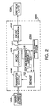
- FIG. 3 shows a representative example of a converter circuit 300 that may be used by energy storage system 230 of FIG. 2 to provide startup power to GENSET 112 from the same source that supplies temporary backup power to DC buss 120.
- Converter circuit 300 includes flywheel energy storage device 302, transformers 304, 306 and 308, diode pairs 310, 312, 314, capacitor 316, terminal 318, diode pairs 320, 322 and 324, and terminals 326.
- Flywheel device 302 produces a three-phase AC output (i.e., phases A, B and C) that is connected across the primaries of transformers 304, 306 and 308.
- the three phase output of the secondaries of transformers 304, 306 and 308 are connected across diode pairs 310, 312 and 314, which rectify the AC output into a DC output.
- the DC signal may be further refined by the addition of small filter capacitor 316 (shown in a dashed box to indicate that the use of capacitor 316 is optional).
- the 24 volt DC output is provided at terminal 318, which may be connected directly to the starter of the engine that drives GENSET 112.
- the three-phase output of flywheel device 302 is also fed to diode pairs 320, 322 and 324, which rectify the three-phase output into a high voltage DC signal that is connected to buss 120 via terminals 326.
- FIG. 3 shows one specific configuration of a converter circuit to produce a 24 volt output from energy storage system 230
- other configurations may also be used without departing from the scope of the present invention.
- a single three-phase transformer could be used in place of individual transformers 304, 306 and 308.
- Another configuration may make use of only two outputs from the secondary and two diode pairs to produce the 24 volt output signal (but the use of all three phases is preferred).
Landscapes
- Engineering & Computer Science (AREA)
- Power Engineering (AREA)
- Business, Economics & Management (AREA)
- Emergency Management (AREA)
- Stand-By Power Supply Arrangements (AREA)
- Charge And Discharge Circuits For Batteries Or The Like (AREA)
- Power Sources (AREA)
Applications Claiming Priority (3)
| Application Number | Priority Date | Filing Date | Title |
|---|---|---|---|
| US08/709,578 US5767591A (en) | 1996-09-09 | 1996-09-09 | Method and apparatus for providing startup power to a genset-backed uninterruptible power supply |
| US709578 | 1996-09-09 | ||
| PCT/US1997/015956 WO1998010503A1 (en) | 1996-09-09 | 1997-09-09 | Methods and apparatus for providing startup power to a genset-backed uninterruptible power supply |
Publications (2)
| Publication Number | Publication Date |
|---|---|
| EP0925628A1 EP0925628A1 (en) | 1999-06-30 |
| EP0925628B1 true EP0925628B1 (en) | 2002-08-14 |
Family
ID=24850439
Family Applications (1)
| Application Number | Title | Priority Date | Filing Date |
|---|---|---|---|
| EP97940968A Expired - Lifetime EP0925628B1 (en) | 1996-09-09 | 1997-09-09 | Methods and apparatus for providing startup power to a genset-backed uninterruptible power supply |
Country Status (9)
| Country | Link |
|---|---|
| US (1) | US5767591A (enExample) |
| EP (1) | EP0925628B1 (enExample) |
| JP (1) | JP2001502519A (enExample) |
| AT (1) | ATE222416T1 (enExample) |
| AU (1) | AU731620B2 (enExample) |
| BR (1) | BR9712812A (enExample) |
| CA (1) | CA2264614C (enExample) |
| DE (1) | DE69714746T2 (enExample) |
| WO (1) | WO1998010503A1 (enExample) |
Families Citing this family (79)
| Publication number | Priority date | Publication date | Assignee | Title |
|---|---|---|---|---|
| US5939799A (en) * | 1997-07-16 | 1999-08-17 | Storage Technology Corporation | Uninterruptible power supply with an automatic transfer switch |
| US6108220A (en) * | 1998-02-20 | 2000-08-22 | Union Switch & Signal, Inc. | Solid state fail-safe control of an AC load utilizing synchronous switching |
| JPH11285167A (ja) * | 1998-03-27 | 1999-10-15 | Canon Inc | 半導体デバイス等の製造装置と製造方法、ならびに電力供給システム |
| FR2782680B1 (fr) * | 1998-08-28 | 2000-11-17 | Alstom Technology | Systeme d'alimentation d'un vehicule a traction electrique |
| KR100698231B1 (ko) * | 1998-10-12 | 2007-03-21 | 산요 덴키 가부시키가이샤 | 무정전 전원장치 |
| US6169390B1 (en) | 1999-05-12 | 2001-01-02 | Abb Power T&D Company Inc. | Flywheel-microturbine system |
| US6134124A (en) * | 1999-05-12 | 2000-10-17 | Abb Power T&D Company Inc. | Universal distributed-resource interface |
| US6175166B1 (en) | 1999-06-14 | 2001-01-16 | Abb Power T&D Company Inc. | System for mitigating voltage disturbances and interruptions for power distribution applications |
| US6172432B1 (en) | 1999-06-18 | 2001-01-09 | Gen-Tran Corporation | Automatic transfer switch |
| US6184593B1 (en) | 1999-07-29 | 2001-02-06 | Abb Power T&D Company Inc. | Uninterruptible power supply |
| US6181028B1 (en) * | 1999-08-19 | 2001-01-30 | Generac Power Systems, Inc. | Transfer mechanism for transferring power between a utility source and a stand-by generator |
| US6657320B1 (en) * | 1999-11-03 | 2003-12-02 | Active Power, Inc. | Integrated flywheel uninterruptible power supply system |
| US6700802B2 (en) * | 2000-02-14 | 2004-03-02 | Aura Systems, Inc. | Bi-directional power supply circuit |
| US6433444B1 (en) | 2000-02-18 | 2002-08-13 | General Electric Company | Modular fault tolerant power distribution system |
| JP2001327083A (ja) * | 2000-05-18 | 2001-11-22 | Ngk Insulators Ltd | 高温二次電池による電力貯蔵及び補償システム |
| IL153107A0 (en) * | 2000-05-31 | 2003-06-24 | Sure Power Corp | Power system utilizing a dc bus |
| US6486627B1 (en) * | 2000-06-23 | 2002-11-26 | Indigo Energy, Inc. | Flywheel uninterruptible power source |
| US6725397B1 (en) | 2000-11-14 | 2004-04-20 | International Business Machines Corporation | Method and system for preserving data resident in volatile cache memory in the event of a power loss |
| US6304006B1 (en) | 2000-12-28 | 2001-10-16 | Abb T&D Technology Ltd. | Energy management uninterruptible power supply system |
| US6693371B2 (en) | 2001-02-06 | 2004-02-17 | American Power Corporation | Integrated uninterruptible power supply enclosure |
| US6807073B1 (en) * | 2001-05-02 | 2004-10-19 | Oltronics, Inc. | Switching type power converter circuit and method for use therein |
| DE10140517A1 (de) * | 2001-08-17 | 2003-02-27 | Philips Corp Intellectual Pty | Schaltungsanordnung zur Steuerung eines Sensors |
| US6657321B2 (en) * | 2001-10-02 | 2003-12-02 | General Electric Company | Direct current uninterruptible power supply method and system |
| US6737762B2 (en) | 2001-10-26 | 2004-05-18 | Onan Corporation | Generator with DC boost for uninterruptible power supply system or for enhanced load pickup |
| US6943531B2 (en) * | 2002-03-20 | 2005-09-13 | Yamaha Hatsudoki Kabushiki Kaisha | Portable power supply incorporating a generator driven by an engine |
| US6831442B2 (en) * | 2002-07-03 | 2004-12-14 | General Motors Corporation | Utilizing zero-sequence switchings for reversible converters |
| US7180210B1 (en) * | 2002-10-11 | 2007-02-20 | Joel Jorgenson | Standby generator integration system |
| AU2003282994A1 (en) * | 2002-10-22 | 2004-05-13 | Youtility, Inc. | Hybrid variable speed generator/uninterruptible power supply power converter |
| US7786616B2 (en) * | 2003-02-07 | 2010-08-31 | Cummins Power Generation Inc. | Generator with DC boost and split bus bidirectional DC-to-DC converter for uninterruptible power supply system or for enhanced load pickup |
| US20060022524A1 (en) * | 2003-02-10 | 2006-02-02 | Bryde Jan H | Distributed power generation, conversion, and storage system |
| US20060017328A1 (en) * | 2003-02-10 | 2006-01-26 | Bryde Jan H | Control system for distributed power generation, conversion, and storage system |
| US20040155527A1 (en) * | 2003-02-10 | 2004-08-12 | Bryde Jan Henrik | Distributed power generation, conversion, and storage system |
| US7042110B2 (en) * | 2003-05-07 | 2006-05-09 | Clipper Windpower Technology, Inc. | Variable speed distributed drive train wind turbine system |
| US7119450B2 (en) * | 2004-06-01 | 2006-10-10 | Illinois Tool Works Inc. | Fuel saving engine driven aircraft ground power device and method of use |
| US7358620B2 (en) * | 2004-09-30 | 2008-04-15 | Rockwell Automation Technologies, Inc. | Methods and apparatus for ride-through operation of a complementary device to a transient power source |
| JP2006217780A (ja) * | 2005-02-07 | 2006-08-17 | Yamaha Motor Co Ltd | インバータ式交流発電装置 |
| US7710081B2 (en) | 2006-10-27 | 2010-05-04 | Direct Drive Systems, Inc. | Electromechanical energy conversion systems |
| US7915760B2 (en) * | 2007-12-12 | 2011-03-29 | Evans Sr Bruce Jonathan | Electric power conservation system for storing electric power for use during off-peak hours |
| US20090152951A1 (en) * | 2007-12-18 | 2009-06-18 | Caterpillar Inc. | Electric system for providing uninterruptible power |
| US7962772B2 (en) | 2008-02-07 | 2011-06-14 | Ainet Registry, Llc | Backup power system and method |
| US8203235B2 (en) * | 2008-04-11 | 2012-06-19 | Liebert Corporation | AC and DC uninterruptible online power supplies |
| US8253298B2 (en) | 2008-07-28 | 2012-08-28 | Direct Drive Systems, Inc. | Slot configuration of an electric machine |
| KR101029249B1 (ko) * | 2009-05-21 | 2011-04-18 | 서울기연(주) | 발전기를 이용한 무정전 전원 공급장치 및 무정전 전원 공급방법 |
| KR200454645Y1 (ko) * | 2009-05-21 | 2011-07-19 | 서울기연(주) | 전원의 자동 절체 시스템 |
| US20110215645A1 (en) * | 2010-03-05 | 2011-09-08 | Active Power, Inc. | Containerized continuous power system and method |
| JP5355617B2 (ja) * | 2011-04-25 | 2013-11-27 | 三菱電機株式会社 | 電源装置 |
| JP5658360B2 (ja) | 2011-05-10 | 2015-01-21 | 三菱電機株式会社 | 直流電源装置および電力変換方法 |
| US10236817B2 (en) * | 2011-11-11 | 2019-03-19 | The Boeing Company | Integrated control architecture and method for a bi-directional AC-to-AC converter |
| JP2013230063A (ja) * | 2012-04-27 | 2013-11-07 | Mitsubishi Electric Corp | 電源装置 |
| US20150061384A1 (en) * | 2013-08-27 | 2015-03-05 | Amazon Technologies, Inc. | Shared Backup Power For Data Centers |
| KR20150069613A (ko) * | 2013-12-13 | 2015-06-24 | 주식회사 엘지씨엔에스 | 무정전 전원 공급 장치(ups)를 활용한 에너지 저장 시스템 |
| US9577471B2 (en) | 2014-02-13 | 2017-02-21 | Power Group International Corporation | Power system for providing an uninterruptible power supply to an external load |
| CN104079064B (zh) * | 2014-06-04 | 2018-01-23 | 华中科技大学 | 一种自备电源系统 |
| US20190113014A1 (en) * | 2016-04-01 | 2019-04-18 | Aldelano Ip Holdings, Llc | Automatic generator start system for a portable generator having electric start |
| US10519933B2 (en) | 2017-04-24 | 2019-12-31 | General Electric Company | Method of operating a wind turbine system including an energy storage system |
| US10523088B2 (en) | 2017-04-24 | 2019-12-31 | General Electric Company | Energy storage system for doubly fed induction generator |
| WO2019021627A1 (ja) * | 2017-07-26 | 2019-01-31 | パナソニックIpマネジメント株式会社 | 電源監視データ処理装置、電源監視データ処理方法、および電源監視データ処理プログラム |
| US12294238B2 (en) | 2017-11-13 | 2025-05-06 | Potencia Industrial Llc | Uninterruptible power supply system with engine start-up |
| US11788499B2 (en) | 2017-11-13 | 2023-10-17 | Potencia Industrial Llc | Uninterruptible power supply system with engine start-up |
| US11025083B2 (en) | 2018-04-24 | 2021-06-01 | General Electric Company | Energy storage system |
| CN214887011U (zh) | 2020-11-24 | 2021-11-26 | 烟台杰瑞石油装备技术有限公司 | 压裂系统 |
| US11746636B2 (en) | 2019-10-30 | 2023-09-05 | Yantai Jereh Petroleum Equipment & Technologies Co., Ltd. | Fracturing apparatus and control method thereof, fracturing system |
| US11680474B2 (en) | 2019-06-13 | 2023-06-20 | Yantai Jereh Petroleum Equipment & Technologies Co., Ltd. | Fracturing apparatus and control method thereof, fracturing system |
| US12173594B2 (en) | 2019-06-13 | 2024-12-24 | Yantai Jereh Petroleum Equipment & Technologies Co., Ltd. | Fracturing system |
| US12326074B2 (en) | 2019-06-13 | 2025-06-10 | Yantai Jereh Petroleum Equipment & Technologies Co., Ltd. | Fracturing apparatus and control method thereof, fracturing system |
| US11710970B2 (en) | 2020-01-17 | 2023-07-25 | BWR Innovations LLC | Remotely controlled electrical power generating system |
| US11018508B1 (en) | 2020-01-17 | 2021-05-25 | BWR Innovations LLC | Electrical power generating system |
| US12156950B2 (en) | 2020-07-08 | 2024-12-03 | BWR Innovations LLC | Software architecture and system for delivering selected sanitation protocols for multiple pathogens and pests |
| EP4182550A4 (en) | 2020-07-13 | 2024-08-07 | Potencia Industrial, LLC | Uninterruptible power supply system with engine start-up |
| US11662384B2 (en) | 2020-11-13 | 2023-05-30 | Yantai Jereh Petroleum Equipment & Technologies Co., Ltd. | Motor malfunction monitoring device, drive motor system and motor malfunction monitoring method |
| CA3157232A1 (en) | 2020-11-24 | 2022-05-24 | Yantai Jereh Petroleum Equipment & Technologies Co., Ltd. | Fracturing system |
| TR202020888A2 (tr) * | 2020-12-18 | 2021-03-22 | Kz Enerji Coezuemleri Ve Dis Tic Ltd Sti | Hi̇bri̇t güç kutusu |
| US11668289B2 (en) | 2021-05-12 | 2023-06-06 | Yantai Jereh Petroleum Equipment & Technologies Co., Ltd. | Fracturing apparatus |
| US12442370B2 (en) * | 2021-04-07 | 2025-10-14 | Yantai Jereh Petroleum Equipment & Technologies Co., Ltd. | Fracturing equipment having multiple electric-power supplies |
| CN214887020U (zh) | 2021-04-07 | 2021-11-26 | 烟台杰瑞石油装备技术有限公司 | 压裂井场系统 |
| US11945338B2 (en) | 2021-08-13 | 2024-04-02 | BWR Innovations LLC | Fuel cell auxiliary power generation system for a vehicle |
| CN115776169A (zh) * | 2021-09-06 | 2023-03-10 | 华为数字能源技术有限公司 | 一种供电系统 |
| WO2023060803A1 (zh) | 2021-10-14 | 2023-04-20 | 烟台杰瑞石油装备技术有限公司 | 压裂设备 |
| WO2023155038A1 (zh) * | 2022-02-15 | 2023-08-24 | 烟台杰瑞石油装备技术有限公司 | 电驱泵送系统及其驱动方法 |
Family Cites Families (16)
| Publication number | Priority date | Publication date | Assignee | Title |
|---|---|---|---|---|
| DE1199393B (de) * | 1956-03-19 | 1965-08-26 | Siemens Ag | Anlage fuer die unterbrechungslose Stromversorgung von Verbrauchern |
| JPS5720573A (en) * | 1980-07-10 | 1982-02-03 | Mitsubishi Electric Corp | Flywheel-type electric energy storage device |
| US4395845A (en) * | 1981-06-08 | 1983-08-02 | Markowitz Edward M | Plant protector |
| US4412170A (en) * | 1981-07-02 | 1983-10-25 | Precise Power Corporation | Motor-generator system providing prolonged uninterrupted power supply to a load |
| US4406950A (en) * | 1981-07-06 | 1983-09-27 | Precise Power Corporation | Greatly prolonged period non-interruptible power supply system |
| FR2511558B1 (fr) * | 1981-08-17 | 1987-04-30 | Aerospatiale | Equipement pour le stockage de l'energie sous forme cinetique et la restitution de celle-ci sous forme electrique, et procede de mise en oeuvre de cet equipement |
| US4471233A (en) * | 1982-08-09 | 1984-09-11 | Emergency Power Engineering, Inc. | Emergency power system |
| US4460834A (en) * | 1983-08-29 | 1984-07-17 | Power Group International Corp. | Uninterruptible power system |
| JPS62107647A (ja) * | 1985-10-31 | 1987-05-19 | 三菱電機株式会社 | フライホイ−ル電源装置 |
| US4686379A (en) * | 1985-12-24 | 1987-08-11 | Eikoh Giken Co., Ltd. | No-break power supply system |
| US4827152A (en) * | 1988-04-18 | 1989-05-02 | Otto Farkas | Uninterruptible power supply system |
| US4857755A (en) * | 1988-09-27 | 1989-08-15 | Comstock W Kenneth | Constant power system and method |
| US5065060A (en) * | 1989-03-06 | 1991-11-12 | Mitsubishi Denki Kabushiki Kaisha | Flywheel type energy storage apparatus |
| US5198698A (en) * | 1991-02-11 | 1993-03-30 | Best Power Technology, Inc. | Auxiliary power supply system for providing dc power on demand |
| JP2656684B2 (ja) * | 1991-06-12 | 1997-09-24 | 三菱電機株式会社 | エレベータの停電時運転装置 |
| US5532525A (en) * | 1994-06-02 | 1996-07-02 | Albar, Inc. | Congeneration power system |
-
1996
- 1996-09-09 US US08/709,578 patent/US5767591A/en not_active Expired - Lifetime
-
1997
- 1997-09-09 AT AT97940968T patent/ATE222416T1/de not_active IP Right Cessation
- 1997-09-09 AU AU42630/97A patent/AU731620B2/en not_active Ceased
- 1997-09-09 WO PCT/US1997/015956 patent/WO1998010503A1/en not_active Ceased
- 1997-09-09 DE DE69714746T patent/DE69714746T2/de not_active Expired - Lifetime
- 1997-09-09 EP EP97940968A patent/EP0925628B1/en not_active Expired - Lifetime
- 1997-09-09 BR BR9712812-0A patent/BR9712812A/pt not_active IP Right Cessation
- 1997-09-09 JP JP10512999A patent/JP2001502519A/ja not_active Ceased
- 1997-09-09 CA CA002264614A patent/CA2264614C/en not_active Expired - Fee Related
Also Published As
| Publication number | Publication date |
|---|---|
| US5767591A (en) | 1998-06-16 |
| AU731620B2 (en) | 2001-04-05 |
| JP2001502519A (ja) | 2001-02-20 |
| BR9712812A (pt) | 1999-11-23 |
| WO1998010503A1 (en) | 1998-03-12 |
| EP0925628A1 (en) | 1999-06-30 |
| DE69714746D1 (de) | 2002-09-19 |
| AU4263097A (en) | 1998-03-26 |
| ATE222416T1 (de) | 2002-08-15 |
| CA2264614A1 (en) | 1998-03-12 |
| DE69714746T2 (de) | 2003-04-24 |
| CA2264614C (en) | 2004-11-23 |
Similar Documents
| Publication | Publication Date | Title |
|---|---|---|
| EP0925628B1 (en) | Methods and apparatus for providing startup power to a genset-backed uninterruptible power supply | |
| US5994794A (en) | Methods and apparatus for providing protection to batteries in an uninterruptible power supply | |
| US6304006B1 (en) | Energy management uninterruptible power supply system | |
| US5646458A (en) | Uninterruptible power system with a flywheel-driven source of standby power | |
| EP1306958B1 (en) | Generator with DC boost | |
| US6845020B2 (en) | Power converter system | |
| EP0500665B1 (en) | Uninterruptible power supply | |
| EP0476431B1 (en) | External backup power supply | |
| JPH06507539A (ja) | 要求に応じてdc電力を供給するための予備電源システム | |
| JPH07238929A (ja) | 磁気軸受装置 | |
| KR101378503B1 (ko) | Dc 전력 시스템 | |
| MXPA99002260A (en) | Methods and apparatus for providing startup power to a genset-backed uninterruptible power supply | |
| JP4276193B2 (ja) | 瞬時電圧低下補償装置の充電方法 | |
| JPS6087635A (ja) | 直流発電機の出力端子の開放故障検出装置 | |
| KR0133492Y1 (ko) | 보조 전원장치 보호회로 | |
| KR200276819Y1 (ko) | 컴퓨터 시스템용 무정전 전원 공급 장치 | |
| JPH0511751U (ja) | 無停電電源装置の制御電源回路 | |
| JPS6389031A (ja) | 無停電電源装置の制御電源回路 | |
| JPS6134835Y2 (enExample) | ||
| JPS6375302A (ja) | 回転機械の軸受潤滑油供給装置 | |
| JPS61244236A (ja) | 無停電電源装置 | |
| WO2004100352A2 (en) | Output augmentation equipment | |
| KR19980013665A (ko) | 전원공급장치의 배터리 충전전압 및 시스템 직류 출력전압 감지회로 및 방법 | |
| JPH05115135A (ja) | 無停電電源装置 | |
| JPH05103434A (ja) | 無停電電源装置 |
Legal Events
| Date | Code | Title | Description |
|---|---|---|---|
| PUAI | Public reference made under article 153(3) epc to a published international application that has entered the european phase |
Free format text: ORIGINAL CODE: 0009012 |
|
| 17P | Request for examination filed |
Effective date: 19990319 |
|
| AK | Designated contracting states |
Kind code of ref document: A1 Designated state(s): AT CH DE FI FR GB LI |
|
| 17Q | First examination report despatched |
Effective date: 19991124 |
|
| GRAG | Despatch of communication of intention to grant |
Free format text: ORIGINAL CODE: EPIDOS AGRA |
|
| GRAG | Despatch of communication of intention to grant |
Free format text: ORIGINAL CODE: EPIDOS AGRA |
|
| GRAH | Despatch of communication of intention to grant a patent |
Free format text: ORIGINAL CODE: EPIDOS IGRA |
|
| GRAH | Despatch of communication of intention to grant a patent |
Free format text: ORIGINAL CODE: EPIDOS IGRA |
|
| GRAA | (expected) grant |
Free format text: ORIGINAL CODE: 0009210 |
|
| AK | Designated contracting states |
Kind code of ref document: B1 Designated state(s): AT CH DE FI FR GB LI |
|
| PG25 | Lapsed in a contracting state [announced via postgrant information from national office to epo] |
Ref country code: LI Free format text: LAPSE BECAUSE OF FAILURE TO SUBMIT A TRANSLATION OF THE DESCRIPTION OR TO PAY THE FEE WITHIN THE PRESCRIBED TIME-LIMIT Effective date: 20020814 Ref country code: FI Free format text: LAPSE BECAUSE OF FAILURE TO SUBMIT A TRANSLATION OF THE DESCRIPTION OR TO PAY THE FEE WITHIN THE PRESCRIBED TIME-LIMIT Effective date: 20020814 Ref country code: CH Free format text: LAPSE BECAUSE OF FAILURE TO SUBMIT A TRANSLATION OF THE DESCRIPTION OR TO PAY THE FEE WITHIN THE PRESCRIBED TIME-LIMIT Effective date: 20020814 Ref country code: AT Free format text: LAPSE BECAUSE OF FAILURE TO SUBMIT A TRANSLATION OF THE DESCRIPTION OR TO PAY THE FEE WITHIN THE PRESCRIBED TIME-LIMIT Effective date: 20020814 |
|
| REF | Corresponds to: |
Ref document number: 222416 Country of ref document: AT Date of ref document: 20020815 Kind code of ref document: T |
|
| REG | Reference to a national code |
Ref country code: GB Ref legal event code: FG4D |
|
| REG | Reference to a national code |
Ref country code: CH Ref legal event code: EP |
|
| REF | Corresponds to: |
Ref document number: 69714746 Country of ref document: DE Date of ref document: 20020919 |
|
| REG | Reference to a national code |
Ref country code: CH Ref legal event code: PL |
|
| ET | Fr: translation filed | ||
| PLBE | No opposition filed within time limit |
Free format text: ORIGINAL CODE: 0009261 |
|
| STAA | Information on the status of an ep patent application or granted ep patent |
Free format text: STATUS: NO OPPOSITION FILED WITHIN TIME LIMIT |
|
| 26N | No opposition filed |
Effective date: 20030515 |
|
| PGFP | Annual fee paid to national office [announced via postgrant information from national office to epo] |
Ref country code: DE Payment date: 20130919 Year of fee payment: 17 |
|
| PGFP | Annual fee paid to national office [announced via postgrant information from national office to epo] |
Ref country code: FR Payment date: 20130919 Year of fee payment: 17 Ref country code: GB Payment date: 20130919 Year of fee payment: 17 |
|
| REG | Reference to a national code |
Ref country code: DE Ref legal event code: R082 Ref document number: 69714746 Country of ref document: DE |
|
| REG | Reference to a national code |
Ref country code: DE Ref legal event code: R119 Ref document number: 69714746 Country of ref document: DE |
|
| GBPC | Gb: european patent ceased through non-payment of renewal fee |
Effective date: 20140909 |
|
| REG | Reference to a national code |
Ref country code: FR Ref legal event code: ST Effective date: 20150529 |
|
| PG25 | Lapsed in a contracting state [announced via postgrant information from national office to epo] |
Ref country code: DE Free format text: LAPSE BECAUSE OF NON-PAYMENT OF DUE FEES Effective date: 20150401 Ref country code: GB Free format text: LAPSE BECAUSE OF NON-PAYMENT OF DUE FEES Effective date: 20140909 |
|
| PG25 | Lapsed in a contracting state [announced via postgrant information from national office to epo] |
Ref country code: FR Free format text: LAPSE BECAUSE OF NON-PAYMENT OF DUE FEES Effective date: 20140930 |