EP0924852A2 - Automatische Kalibrierung der Parameter eines feldorietierten Aufzugmotorantriebs unter Verwendung von Messungen im Motorstillstand - Google Patents
Automatische Kalibrierung der Parameter eines feldorietierten Aufzugmotorantriebs unter Verwendung von Messungen im Motorstillstand Download PDFInfo
- Publication number
- EP0924852A2 EP0924852A2 EP98310410A EP98310410A EP0924852A2 EP 0924852 A2 EP0924852 A2 EP 0924852A2 EP 98310410 A EP98310410 A EP 98310410A EP 98310410 A EP98310410 A EP 98310410A EP 0924852 A2 EP0924852 A2 EP 0924852A2
- Authority
- EP
- European Patent Office
- Prior art keywords
- motor
- rated
- calculating
- imag
- frequency
- Prior art date
- Legal status (The legal status is an assumption and is not a legal conclusion. Google has not performed a legal analysis and makes no representation as to the accuracy of the status listed.)
- Granted
Links
Images
Classifications
-
- H—ELECTRICITY
- H03—ELECTRONIC CIRCUITRY
- H03H—IMPEDANCE NETWORKS, e.g. RESONANT CIRCUITS; RESONATORS
- H03H9/00—Networks comprising electromechanical or electro-acoustic devices; Electromechanical resonators
- H03H9/02—Details
- H03H9/05—Holders; Supports
- H03H9/10—Mounting in enclosures
- H03H9/1007—Mounting in enclosures for bulk acoustic wave [BAW] devices
- H03H9/1035—Mounting in enclosures for bulk acoustic wave [BAW] devices the enclosure being defined by two sealing substrates sandwiching the piezoelectric layer of the BAW device
-
- H—ELECTRICITY
- H02—GENERATION; CONVERSION OR DISTRIBUTION OF ELECTRIC POWER
- H02P—CONTROL OR REGULATION OF ELECTRIC MOTORS, ELECTRIC GENERATORS OR DYNAMO-ELECTRIC CONVERTERS; CONTROLLING TRANSFORMERS, REACTORS OR CHOKE COILS
- H02P21/00—Arrangements or methods for the control of electric machines by vector control, e.g. by control of field orientation
- H02P21/14—Estimation or adaptation of machine parameters, e.g. flux, current or voltage
- H02P21/16—Estimation of constants, e.g. the rotor time constant
-
- H—ELECTRICITY
- H03—ELECTRONIC CIRCUITRY
- H03H—IMPEDANCE NETWORKS, e.g. RESONANT CIRCUITS; RESONATORS
- H03H9/00—Networks comprising electromechanical or electro-acoustic devices; Electromechanical resonators
- H03H9/02—Details
- H03H9/05—Holders; Supports
- H03H9/0595—Holders; Supports the holder support and resonator being formed in one body
Definitions
- This invention relates to calibrating a field-oriented motor drive and more particularly to automatic calibration of field-oriented (or vector-controlled) drive parameters for an elevator motor drive.
- Objects of the invention include provision of automatic, on-site, calibration of motor parameters for field-oriented drives and/or controls for elevators, which does not require removal or uncoupling of the motor from the elevator system, and which uses only standstill measurements of the motor.
- the present invention represents a significant improvement over the prior art by providing automatic calibration of a field-oriented (or vector-controlled) induction motor controller for an elevator system based on standstill measurements of the induction motor.
- the invention provides motor parameters such as the rotor time constant ( ⁇ R ), torque constant (K T *), and rated magnetizing current I dRATED , without disconnecting the motor from the elevator system or from the gearbox.
- the invention also computes transient inductance L ⁇ , magnetizing inductance L ⁇ , stator resistance Rs, and rated torque current I qRATED , as needed by a given application. Further, the invention does not require a specially trained engineer with special test equipment to tune the motor/drive system.
- the invention greatly reduces cost associated with tuning the motor drive when new motors drives are retrofit into job sites. Accordingly, automatic calibration of motor parameters at the field site saves both time and money. As a result, the present invention makes it more attractive for building owners to upgrade their elevator systems to modern controls, which are currently economically impractical due to the high cost of determining parameters of older motors found in modernization job sites.
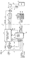
- Fig. 1 is a schematic block diagram of a motor controller with auto-calibration logic, in accordance with the present invention.
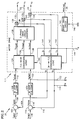
- Fig. 2 is a schematic block diagram of a current regulator/motor drive, in accordance with the present invention.
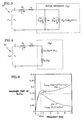
- Fig. 3 is a schematic drawing of an equivalent circuit model of an induction motor controlled by field orientation, in accordance with the present invention.
- Fig. 4 is a simplified schematic diagram of the equivalent circuit of Fig. 3, in accordance with the present invention.
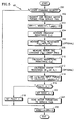
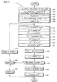
- Fig. 5 is a logic flow diagram of the auto-calibration logic of Fig. 1, in accordance with the present invention.
- Fig. 6 is a graph of the imaginary part of the rotor impedance and of the motor impedance versus frequency, in accordance with the present invention.
- Fig. 7 is a logic flow diagram of a portion of the auto-calibration logic of Fig. 5, in accordance with the present invention.
- a portion of an elevator motor controller 7 shown to the left of the line 9, includes a field-oriented (or vector-based) motor control that has two control loops each corresponding to a different control axis, a d-axis relating to motor magnetization, and a q-axis relating to torque.
- the d-axis loop has a d-axis current reference input signal I dREF provided on a line 14.
- I dREF is set to a predetermined constant value so as to provide appropriate magnetic flux in the motor based on motor magnetization curves, e.g., I dRATED or I NO-LOAD , discussed more hereinafter.
- the I dREF signal is fed to a field-oriented current regulator/motor drive circuit 20, described more hereinafter with Fig. 2.
- the q-axis current loop has a first q-axis current reference input signal I qREF1 on a line 15 is fed to one input of a switch 19.
- I qREF1 is provided by other logic (not shown), such as speed loop compensation logic (not shown), which closes a motor speed control loop which provides the q-axis current reference signal to the controller when it is not in auto-calibration.
- the other input to the switch 19 is a second q-axis current reference input signal I qREF2 on a line 17.
- the output of the switch 19 is the q-axis current loop reference signal I qREF on a line 18, which is set equal to I qREF1 or I qREF2 based on the state of the MODE signal provided to the switch 19 on the line 13.
- the I qREF signal is fed to the field-oriented current regulator/motor drive circuit 20, described more hereinafter with Fig. 2.
- Model LUGA-225LB-04A by Loher, having a rated power of 45KW, rated voltage of 355 volts, rated speed of 1480, and rated frequency of 50 Hz, in a geared configuration
- Model 156MST by Tatung (of Taiwan), having a rated power of 40KW, rated voltage of 500 volts, rated speed of 251, and rated frequency of 16.7 Hz, in a gearless configuration.
- Other motors having other rated parameters may be used if desired.
- the circuit 20 provides three phase voltage signals Vx,Vy,Vz on lines 22 to a motor 24, e.g., a three phase induction motor.
- the motor 24 is connected by a mechanical linkage 26, e.g, a shaft and/or a gearbox, to a sheave 28.
- a rope or cable 30 is wrapped around the sheave 28 and has one end connected to an elevator car 32 and the other end connected to a counterweight 34.
- the weight of the counterweight is typically equal to the weight of an empty car plus 40-50% of the max load in the car.
- elevator system configurations and with or without a counterweight, with or without a gearbox, may be used if desired to convert the output torque of the motor 24 to movement of the elevator cab 32, such as dual lift (where two elevator cars are connected to a single rope, the cars move in opposite directions and each car provides a counterweight for the other car), drum machine (where the rope is wrapped around a drum driven by a motor), etc.
- dual lift where two elevator cars are connected to a single rope, the cars move in opposite directions and each car provides a counterweight for the other car
- drum machine where the rope is wrapped around a drum driven by a motor
- a brake 37 e.g., an electro-magnetic actuated disk brake, is disposed on the shaft 26, and is driven by an electrical brake command signal BRKCMD on a line 38 from the circuit 20.
- the brake 37 when activated or “dropped”, clamps onto the shaft 26 and prevents the motor shaft 26 from turning, i.e., locks the rotor, and thus prevents the sheave 28 from moving.
- the field-oriented current regulator/motor drive 20 of Fig. 1 comprises two current control loops, one for the d-axis current Id and one for q-axis current Iq.
- the Id loop receives the I dREF signal on the line 14 to a positive input to a summer 102.
- a measured or feedback d-axis current signal Id on a line 104 is fed to a negative input to the summer 102.
- the output of the summer 102 is an error signal I dERR on a line 106 which is fed to control compensation logic 108, such as proportional-plus-integral (P-I) current loop control. Other current loop control compensation may be used if desired.
- the logic 108 provides a d-axis voltage command signal V dCMD on a line 110.
- the Iq loop receives the I qREF signal on the line 18 to a positive input to a summer 114.
- a measured or feedback q-axis current signal Iq on a line 116 is fed to a negative input to the summer 114.
- the output of the summer 114 is an error signal I qERR on a line 118 which is fed to control compensation logic 120, e.g., proportional-plus-integral (P-I) logic similar to the logic 108.
- control compensation logic 120 e.g., proportional-plus-integral (P-I) logic similar to the logic 108.
- the output of the logic 120 is a q-axis voltage command signal V qCMD on a line 122.
- Other control compensation e.g., proportional, lead-lag, etc., may be used for the logics 108,120.
- the form of compensation used is not critical to the present invention.
- the voltage commands V dCMD and V qCMD are fed to known field-oriented to three-phase conversion logic 124 which converts the d-axis and q-axis voltage commands to three phase voltage commands V XCMD , V YCMD , V ZCMD on lines 126.
- the phase voltage commands V XCMD , V YCMD , V ZCMD are fed to a known three phase drive circuit (or inverter) 128 which provides three phase voltages V X ,V Y ,V Z on lines 130, 132, 134, respectively (collectively, the lines 22), to drive the motor 24.
- each of the voltage commands V XCMD , V YCMD , V ZCMD on lines 126 are converted to percent duty cycle commands indicative of the corresponding input voltage level.
- the percent duty cycle is converted into a pulse-width-modulated drive signal which drives power transistors to provide the pulse-width-modulated, variable frequency, three phase voltages V X ,V Y ,V Z on lines 130, 132, 134, respectively.
- the conversions within the drive 128 are performed using electronic components and/or software well known in the art of motor drive circuits. Any other type of drive circuit that receives input voltage commands and provides output phase voltages may be used, and the phase voltages need not be pulse-width modulated.
- Phase currents I X ,I Y ,I Z associated with the voltages V X ,V Y ,V Z , respectively, are measured by known current sensors 136, 138, 140, e.g., closed-loop Hall-effect current sensors (such as LEMS), respectively, and are provided on lines 132, 134, 136, respectively.
- the phase currents I X ,I Y ,I Z are fed to known three phase to field oriented conversion logic 142, which provides a known conversion from phase currents to d-axis and q-axis currents on the lines 104, 116 which are fed to the summers 102,114, respectively.
- the converters 124,150 provide known conversions between vector (d and q axis) parameters and per-phase parameters, such as that described in D. Novotny, et al, "Vector Control and Dynamics of AC Drives", Oxford University Press, 1996, Ch 5, pp 203-251.
- the converters 124,15 may likely implement such conversions in software using a microprocessor or the like.
- the motor drive logic 111 also includes a brake drive circuit 145 which receives an input signal BRK on a line 146 and provides a BRKCMD signal on the line 38.
- the present invention comprises auto-calibration logic 48 which automatically computes the motor parameters ⁇ R , K T *, I dRATED , and provides ⁇ R on the line 144 to the circuit 20, provides I dRATED as I dREF on the line 14 to the circuit 20, and provides K T * on a line 160 to speed loop compensation logic (not shown).
- the logic 48 also computes other motor parameters such as transient inductance L ⁇ , magnetizing inductance L ⁇ , stator resistance Rs (or R1) and rated torque current I qRATED .
- the logic 48 receives Vq and Iq from the circuit 20.
- the logic 48 also provides the current reference signal IqREF2 to the switch 19, and provides I dREF to the circuit 20 on the line 14.
- the logic 48 comprises known electronic components, which may include a microprocessor, interface circuitry, memory, software, and/or firmware, capable of performing the functions described herein.
- the logic 48 also provides the MODE1 signal on the line 13 to the switch 19.
- the MODE1 flag causes the current reference signal I qREF2 from the calibration logic 48 to be fed to the logic 20.
- the logic 48 also provides a break request signal BRK on the line 146 to the circuit 20.
- the calculation logic 48 also communicates with a service tool 80 over a serial link 82.
- the service tool 80 includes a display 84 and a keypad (or keyboard) 86 for entering data into the service tool 80 and over the link 82 to the controller 7.
- the logic 48 receives a start command over the link 82 from the service tool 80, which controls when auto-calibration is started.
- the logic 66 also provides a DONE signal and a FAULT signal to the service tool 80 over the link 82.
- the DONE signal indicates when auto-calibration has completed without faults and the FAULT signal indicates when a fault has been detected during auto-calibration.
- a known equivalent circuit 90 of an induction motor is similar to that described in "Vector Control and Dynamics of AC Drives", Novotny and Lipo, Oxford 1996, Chapter 5.
- Fig. 3 is a per-phase equivalent circuit for AC steady state operation where the current I1 and voltage V1 are phasor quantities.
- the circuit 90 comprises a resistor Rs in series with an equivalent "transient” inductor L ⁇ in series with a rotor impedance Z R which comprises a "magnetizing" inductance L ⁇ in parallel with an equivalent resistance R 2 /S.
- rotor time constant ⁇ R and motor torque constant K T * are related to the parameters of the circuit 90 as follows:
- the circuit 92 is an equivalent to the circuit 90 of Fig. 3 with the rotor impedance Z R transformed into an equivalent series circuit impedance having a real part Real(Z R ) and an imaginary part Imag(Z R ) equal to ⁇ Lx.
- the equivalent circuit 92 with the transformation of Z R is useful for determining the rotor time constant ⁇ R (discussed more hereinafter).
- a top level flow chart for the logic 48 begins at a step 200 which determines whether a start command has been received from the service tool 80. If it has not, the logic exits. If a start command has been received, a step 202 requests and receives motor parameters from the service tool 80 over the link 82 (Fig. 1), which are entered by service personnel.
- the motor parameters received are: the rated motor shaft power in watts (PWR_RATED); the rated motor speed in rpm (RPM_RATED); the rated rms line-to-line voltage in volts (VLL_RATED); the rated frequency in hertz (HZ_RATED); and number of poles (POLES), all of which may be obtained from the motor nameplate data.
- a step 204 measures the transient inductance L ⁇ , by providing a sinusoidal current signal into the q-axis of the reference current I qREF2 on the line 17 (Fig. 1) at a frequency F HIGH high enough such that the motor impedance will be dominated by the transient inductance L ⁇ , e.g., 31.25 Hertz. Other frequencies may be used if desired, e.g., greater than 30 Hz.
- the sinewave input signal is generated digitally by a signal processor, such as a digital signal processor, e.g., a Motorola DSP 56002 processor, with an update (or sample) rate of 5KHz. Other hardware and/or software techniques or update rates may be used to generate the sinusoidal input signals.
- the step 204 reads the q-axis feedback current Iq and the q-axis output voltage Vq (equal to the motor current I 1 and motor voltage V 1 , respectively, as discussed hereinbefore).
- the step 204 uses the aforementioned digital signal processor to perform a Discrete Fourier Transform (DFT) of Iq and Vq to determine the first harmonic Fourier coefficients.
- DFT Discrete Fourier Transform
- the first harmonic is used to calculate the impedance primarily so that non-linearities in the system do not distort the calculation.
- a DFT standard sine and cosine waves of unit amplitude at the test frequency are generated within the logic 48.
- the measured signal (Iq,Vq) is multiplied by the standard sinewave and the product is integrated over one period of the excitation to yield the Fourier series coefficient A of the signal. Multiplying the signal by the standard cosine and integrating yields the B coefficient.
- integrating over 15 periods of the input signal it is sufficient to filter out any transients in the system response. Other numbers of periods may be used if desired.
- other types of Fourier transforms may be used if desired, e.g., a Fast Fourier Transform (FFT), etc., provided the first harmonic of the desired signal is obtained.
- any other filtering or spectrum analysis technique may be used for determining the first harmonic of the desired signals.
- the step 204 then computes the real and imaginary parts of Z M from the Fourier coefficients.
- the imaginary part of the motor impedance Z M at F HIGH Hertz is dominated by the transient inductance term ⁇ L ⁇ .
- R TOT Real(Zm) @ F HIGH
- F HIGH used in step 204
- the inductance L ⁇ in the circuit 90 is large and the real part of Z M will be equal to R TOT .
- the value of R TOT is saved for later use to calculate Rs (see step 212).
- a step 208 measures the rotor time constant ⁇ R as follows.
- the step 208 produces a progression of low frequency sinusoidal input q-axis reference currents I qREF2 from 0.1 to 8.0 Hertz in increments defined by a search algorithm, discussed hereinafter.
- the sinewave input signal is generated digitally as discussed hereinbefore with step 204.
- the motor current Iq and voltage Vq are measured and a DFT of the current I 1 and the motor voltage V 1 signals are computed separately.
- the fundamental or first harmonic Fourier coefficients are obtained as discussed hereinbefore with step 204.
- a known search algorithm e.g., a "golden section line search” algorithm, varies the input frequency and determines the frequency Fpeak at which the maximum value of ⁇ Lx occurs.
- a step 210 calculates the magnetizing inductance L ⁇ .
- the ⁇ L X is also equal to 1 ⁇ 2 ⁇ L ⁇ (the magnetizing reactance).
- the rotor impedance Z R is equal to j ⁇ L ⁇ in parallel with R 2 , as shown below:
- Z R j ⁇ L ⁇ R 2 /(R 2 + j ⁇ L ⁇ )
- Z R ⁇ 2 L ⁇ 2 R 2 /(R 2 2 + ⁇ 2 L ⁇ 2 ) + j ⁇ L ⁇ R 2 2 /(R 2 2 + ⁇ 2 L ⁇ 2 )
- R 2 L ⁇ / ⁇ R where L ⁇ and ⁇ R were previously calculated in steps 204,208, respectively.
- a step 214 uses L ⁇ , ⁇ R , and the input parameters PWR_RATED, RPM_RATED, VLL_RATED, HZ_RATED, and POLES, obtained in the step 202, to simulate motor parameters and to iterate and calculate the rated magnetizing current I dRATED , and the torque constant K T *, as shown in Fig. 7.
- a step 300 calculates the rated rotational speed of the motor referred to the electrical reference frame ⁇ R_ RATED.
- a step 302 converts rated line-to-line voltage (VLL_RATED) to rated line-to-neutral voltage (or per-phase voltage) Vph_RATED.
- a step 303 calculates the rated torque T_RATED based on rated power and rated RPM.
- a step 304 calculates the stator inductance Ls as the sum of the transient inductance L ⁇ and the magnetizing L ⁇ .
- a step 306 calculates an initial value for simulated d-axis current Id* based on a first order approximation of Id using rated voltage and speed.
- a step 308 sets a variable COUNT equal to zero.
- a series of steps 310 - 322 calculates K T * and a simulated motor voltage V M * using various simulated motor parameters based on the value of L ⁇ calculated in step 210 (Fig. 5), the parameters calculated in steps 300-308 above, and using known relationships for a field-oriented motor controller, some of which are discussed hereinbefore.
- a step 310 calculates the torque constant K T * based on L ⁇ calculated in step 210 (Fig. 5) and the current value of the magnetizing current Id*.
- a step 312 calculates the torque current Iq*.
- a step 314 calculates a simulated slip frequency ⁇ S * which is used in a next step 316 to calculate a simulated electrical current frequency ⁇ E * which is equal to the rotational frequency (or speed) of the motor (emulated as the rated speed) ⁇ R_ RATED plus the slip frequency ⁇ S *.
- a step 318 calculates a simulated q-axis output voltage Vq* based on the magnetizing current Id* and a step 320 calculates a simulated d-axis output voltage Vd* based on the torque current Iq*. Then, a step 322 calculates a simulated vector sum total motor voltage Vm* equal to the square root of the sum of the squares of the d-axis and q-axis output voltages Vd*,Vq*, respectively.
- a step 324 calculates a Ratio parameter equal to the ratio of the rated phase voltage Vph_RATED to the simulated per-phase motor voltage Vm*. The logic iterates until the Ratio goes to 1 within the desired tolerance, e.g., 0.001. When the ratio equals 1 the value of Id* will produce the rated voltage at the rated RPM and rated torque.
- a step 326 calculates a next value for Id* equal to the value of the Ratio times the current value of Id*.
- a step 328 checks whether Ratio is within a predetermined tolerance of 1, e.g., 0.001. If it is not within the desired tolerance, a step 330 checks whether COUNT is greater than or equal to ten (i.e., whether the loop has iterated at least ten times). If the loop has iterated at least ten times, a FAULT flag is set equal to 1 at a step 332 and output to the service tool 80 over the link 82 (Fig. 1) and the logic is exited. If it has iterated less than ten times, a step 334 increments COUNT by one and the logic 214 goes the step 310 to iterate again.
- a step 340 sets the d-axis current reference I dREF equal to Id* which is equal to I dRATED and a step 344 sets I qRATED equal to Iq*. Then the logic 214 exits and returns to the logic 48 of Fig. 5.
- step 224 some or all of the motor parameters ⁇ R , K T *, I dRATED , L ⁇ , L ⁇ , Rs, and I qRATED are transmitted via the serial link 82 to the service tool 80 in a step 224.
- the service tool 80 displays the parameters for use by the service personnel.
Landscapes
- Physics & Mathematics (AREA)
- Acoustics & Sound (AREA)
- Engineering & Computer Science (AREA)
- Power Engineering (AREA)
- Control Of Ac Motors In General (AREA)
- Elevator Control (AREA)
Applications Claiming Priority (2)
| Application Number | Priority Date | Filing Date | Title |
|---|---|---|---|
| US08/996,265 US5883344A (en) | 1997-12-22 | 1997-12-22 | Automatic calibration of field-oriented elevator motor drive parameters using standstill motor measurements |
| US996265 | 1997-12-22 |
Publications (3)
| Publication Number | Publication Date |
|---|---|
| EP0924852A2 true EP0924852A2 (de) | 1999-06-23 |
| EP0924852A3 EP0924852A3 (de) | 2000-05-24 |
| EP0924852B1 EP0924852B1 (de) | 2007-02-14 |
Family
ID=25542696
Family Applications (1)
| Application Number | Title | Priority Date | Filing Date |
|---|---|---|---|
| EP98310410A Expired - Lifetime EP0924852B1 (de) | 1997-12-22 | 1998-12-18 | Automatische Kalibrierung der Parameter eines feldorientierten Aufzugmotorantriebs unter Verwendung von Messungen im Motorstillstand |
Country Status (5)
| Country | Link |
|---|---|
| US (1) | US5883344A (de) |
| EP (1) | EP0924852B1 (de) |
| JP (1) | JP4205795B2 (de) |
| CN (1) | CN1090404C (de) |
| DE (1) | DE69837073T2 (de) |
Cited By (6)
| Publication number | Priority date | Publication date | Assignee | Title |
|---|---|---|---|---|
| EP0924851A2 (de) * | 1997-12-22 | 1999-06-23 | Otis Elevator Company | Automatische Feinabstimmung der Rotorzeitkonstanten und des Magnetisierungsstromes in feldorientierten Aufzugsmotorantrieben |
| EP0924850A2 (de) * | 1997-12-22 | 1999-06-23 | Otis Elevator Company | Automatische Kalibrierung der Stromregler-Kompensation eines Aufzugmotorantriebs mit blockiertem Rotor |
| EP0933869A2 (de) * | 1997-12-22 | 1999-08-04 | Otis Elevator Company | Automatische Feinabstimmung der Rotorzeitkonstante für eine feldorientierten Aufzugsantriebsmotor |
| EP0936730A2 (de) * | 1997-12-22 | 1999-08-18 | Otis Elevator Company | Selbsttätiger Inbetriebnahmeregler für ein feldorientiertes Aufzugsmotorantriebssystem |
| EP1715576A1 (de) * | 2005-04-22 | 2006-10-25 | ABB Oy | Methode zur Bestimmung der Summe des Stator- und Rotor- Widerstandes |
| CN105680751A (zh) * | 2016-03-11 | 2016-06-15 | 深圳易能电气技术股份有限公司 | 实时读取和发送电机电阻、电感和磁链的方法及系统 |
Families Citing this family (23)
| Publication number | Priority date | Publication date | Assignee | Title |
|---|---|---|---|---|
| KR100459694B1 (ko) * | 1998-04-08 | 2005-04-06 | 삼성전자주식회사 | 모터 토크 상수 측정방법 |
| US6211634B1 (en) * | 1999-07-29 | 2001-04-03 | Otis Elevator Company | Method and apparatus for initialization and operation of field-commutated motors and machines incorporating field-commutated motors |
| US6452360B1 (en) | 1999-12-03 | 2002-09-17 | Square D. Company | Auto tuning and parameter identification of a control circuit |
| US6401875B1 (en) * | 2001-02-12 | 2002-06-11 | Otis Elevator Company | Absolute position sensing method and apparatus for synchronous elevator machines by detection stator iron saturation |
| US6566840B1 (en) | 2002-02-11 | 2003-05-20 | Ford Global Technologies, Inc. | Method and system for self-calibration of an induction machine drive |
| US6646412B2 (en) | 2002-02-11 | 2003-11-11 | Ford Global Technologies, Llc | Method and system for controlling torque in a powertrain that includes an induction motor |
| US6756763B2 (en) * | 2002-05-02 | 2004-06-29 | Visteon Global Technologies, Inc. | Sensorless induction motor control |
| US6670785B1 (en) * | 2002-06-20 | 2003-12-30 | Ford Motor Company | Electrical machine drive system and method |
| US6838852B1 (en) | 2003-04-01 | 2005-01-04 | General Motors Corporation | Plug and play electric machine |
| DE602005010675D1 (de) * | 2005-06-02 | 2008-12-11 | Abb Oy | Verfahren zur Ermittlung der Rotorzeitkonstanten einer Asynchronmaschine |
| JP4946118B2 (ja) * | 2006-03-23 | 2012-06-06 | 株式会社Ihi | 回転機制御装置及び回転機制御方法 |
| US8210319B2 (en) * | 2007-08-31 | 2012-07-03 | John W. Boyd | Hydraulic elevating platform assembly |
| DE102009045822A1 (de) * | 2009-10-20 | 2011-04-28 | Robert Bosch Gmbh | Elektronisch kommutierter Elektromotor mit kalibrierter Motormomentkonstante |
| ITVI20100066A1 (it) * | 2010-03-12 | 2011-09-13 | Sael S R L | Procedimento per stimare i parametri del circuito equivalente di un motore asincrono, particolarmente in un azionamento vettoriale sensorless. |
| CN103064021B (zh) * | 2011-10-18 | 2015-12-09 | 台达电子企业管理(上海)有限公司 | 感应电机励磁参数的测量装置及方法 |
| CN103185839B (zh) * | 2011-12-30 | 2015-07-08 | 台达电子企业管理(上海)有限公司 | 永磁电机电感参数测量装置及其方法 |
| US20140285124A1 (en) * | 2013-03-12 | 2014-09-25 | Universiteit Gent | Control method and device therefor |
| CN103326656B (zh) * | 2013-06-09 | 2015-09-16 | 深圳市汇川技术股份有限公司 | 异步电机转子磁场定向角度修正系统及方法 |
| US9573789B2 (en) | 2014-03-27 | 2017-02-21 | Thyssenkrupp Elevator Corporation | Elevator load detection system and method |
| US10787340B2 (en) | 2016-06-13 | 2020-09-29 | Otis Elevator Company | Sensor and drive motor learn run for elevator systems |
| US11007101B2 (en) | 2017-05-02 | 2021-05-18 | Liko Research & Development Ab | Adaptive compensation of wear in person lifting assemblies |
| CN111913104B (zh) | 2019-05-08 | 2023-01-13 | 博格华纳公司 | 用于电动马达的调试过程中确定马达参数的方法 |
| EP3885300B1 (de) * | 2020-03-27 | 2024-05-01 | KONE Corporation | Verfahren zur identifizierung von magnetisierungachsen- und drehmomentachseinduktivitäten eines permanentmagnetmotors eines aufzugs, und aufzugsantriebseinheit |
Citations (8)
| Publication number | Priority date | Publication date | Assignee | Title |
|---|---|---|---|---|
| DE3715462A1 (de) * | 1986-05-09 | 1987-11-12 | Hitachi Ltd | Verfahren und vorrichtung zur steuerung eines stromrichters mit selbsteinstellung von steuerparametern |
| DE4411149A1 (de) * | 1993-03-31 | 1995-02-02 | Otis Elevator Co | Einer Phase eines Stators eines Motors mit Trägheitsverhalten zugeführte Rechteckspannung führt zu einer leichten Identifikation von Motorparametern |
| EP0704709A2 (de) * | 1994-09-29 | 1996-04-03 | LUST ANTRIEBSTECHNIK GmbH | Verfahren zur Bestimmung der elektrischen Parameter von Asynchronmotoren |
| US5689169A (en) * | 1995-03-10 | 1997-11-18 | Allen-Bradley Company, Inc. | Transient inductance identifier for motor control |
| EP0924851A2 (de) * | 1997-12-22 | 1999-06-23 | Otis Elevator Company | Automatische Feinabstimmung der Rotorzeitkonstanten und des Magnetisierungsstromes in feldorientierten Aufzugsmotorantrieben |
| EP0924850A2 (de) * | 1997-12-22 | 1999-06-23 | Otis Elevator Company | Automatische Kalibrierung der Stromregler-Kompensation eines Aufzugmotorantriebs mit blockiertem Rotor |
| EP0933869A2 (de) * | 1997-12-22 | 1999-08-04 | Otis Elevator Company | Automatische Feinabstimmung der Rotorzeitkonstante für eine feldorientierten Aufzugsantriebsmotor |
| EP0936730A2 (de) * | 1997-12-22 | 1999-08-18 | Otis Elevator Company | Selbsttätiger Inbetriebnahmeregler für ein feldorientiertes Aufzugsmotorantriebssystem |
Family Cites Families (1)
| Publication number | Priority date | Publication date | Assignee | Title |
|---|---|---|---|---|
| US5476158A (en) * | 1993-03-31 | 1995-12-19 | Otis Elevator Company | Rotor time constant adaptation for induction motor in vector controlled elevator drive |
-
1997
- 1997-12-22 US US08/996,265 patent/US5883344A/en not_active Expired - Lifetime
-
1998
- 1998-12-18 EP EP98310410A patent/EP0924852B1/de not_active Expired - Lifetime
- 1998-12-18 DE DE69837073T patent/DE69837073T2/de not_active Expired - Lifetime
- 1998-12-18 JP JP36043298A patent/JP4205795B2/ja not_active Expired - Fee Related
- 1998-12-21 CN CN98125532A patent/CN1090404C/zh not_active Expired - Fee Related
Patent Citations (8)
| Publication number | Priority date | Publication date | Assignee | Title |
|---|---|---|---|---|
| DE3715462A1 (de) * | 1986-05-09 | 1987-11-12 | Hitachi Ltd | Verfahren und vorrichtung zur steuerung eines stromrichters mit selbsteinstellung von steuerparametern |
| DE4411149A1 (de) * | 1993-03-31 | 1995-02-02 | Otis Elevator Co | Einer Phase eines Stators eines Motors mit Trägheitsverhalten zugeführte Rechteckspannung führt zu einer leichten Identifikation von Motorparametern |
| EP0704709A2 (de) * | 1994-09-29 | 1996-04-03 | LUST ANTRIEBSTECHNIK GmbH | Verfahren zur Bestimmung der elektrischen Parameter von Asynchronmotoren |
| US5689169A (en) * | 1995-03-10 | 1997-11-18 | Allen-Bradley Company, Inc. | Transient inductance identifier for motor control |
| EP0924851A2 (de) * | 1997-12-22 | 1999-06-23 | Otis Elevator Company | Automatische Feinabstimmung der Rotorzeitkonstanten und des Magnetisierungsstromes in feldorientierten Aufzugsmotorantrieben |
| EP0924850A2 (de) * | 1997-12-22 | 1999-06-23 | Otis Elevator Company | Automatische Kalibrierung der Stromregler-Kompensation eines Aufzugmotorantriebs mit blockiertem Rotor |
| EP0933869A2 (de) * | 1997-12-22 | 1999-08-04 | Otis Elevator Company | Automatische Feinabstimmung der Rotorzeitkonstante für eine feldorientierten Aufzugsantriebsmotor |
| EP0936730A2 (de) * | 1997-12-22 | 1999-08-18 | Otis Elevator Company | Selbsttätiger Inbetriebnahmeregler für ein feldorientiertes Aufzugsmotorantriebssystem |
Non-Patent Citations (1)
| Title |
|---|
| DATABASE INSPEC [Online] INSTITUTE OF ELECTRICAL ENGINEERS, STEVENAGE, GB SCHIERLING H: "Self-commissioning-a novel feature of modern inverter-fed induction motor drives" Database accession no. 3239252 XP000892216 & THIRD INTERNATIONAL CONFERENCE ON POWER ELECTRONICS AND VARIABLE-SPEED DRIVES (CONF. PUBL. NO.291), LONDON, UK, 13-15 JULY 1988, pages 287-290, 1988, London, UK, IEE, UK ISBN: 0-85296-364-5 * |
Cited By (11)
| Publication number | Priority date | Publication date | Assignee | Title |
|---|---|---|---|---|
| EP0924851A2 (de) * | 1997-12-22 | 1999-06-23 | Otis Elevator Company | Automatische Feinabstimmung der Rotorzeitkonstanten und des Magnetisierungsstromes in feldorientierten Aufzugsmotorantrieben |
| EP0924850A2 (de) * | 1997-12-22 | 1999-06-23 | Otis Elevator Company | Automatische Kalibrierung der Stromregler-Kompensation eines Aufzugmotorantriebs mit blockiertem Rotor |
| EP0933869A2 (de) * | 1997-12-22 | 1999-08-04 | Otis Elevator Company | Automatische Feinabstimmung der Rotorzeitkonstante für eine feldorientierten Aufzugsantriebsmotor |
| EP0936730A2 (de) * | 1997-12-22 | 1999-08-18 | Otis Elevator Company | Selbsttätiger Inbetriebnahmeregler für ein feldorientiertes Aufzugsmotorantriebssystem |
| EP0924850B1 (de) * | 1997-12-22 | 2006-06-07 | Otis Elevator Company | Automatische Kalibrierung der Stromregler-Kompensation eines Aufzugmotorantriebs mit blockiertem Rotor |
| EP0936730B1 (de) * | 1997-12-22 | 2006-06-21 | Otis Elevator Company | Selbsttätiger Inbetriebnahmeregler für ein feldorientiertes Aufzugsmotorantriebssystem |
| EP0933869B1 (de) * | 1997-12-22 | 2006-06-21 | Otis Elevator Company | Automatische Feinabstimmung der Rotorzeitkonstante für eine feldorientierten Aufzugsantriebsmotor |
| EP0924851B1 (de) * | 1997-12-22 | 2006-08-30 | Otis Elevator Company | Automatische Feinabstimmung der Rotorzeitkonstanten und des Magnetisierungsstromes in feldorientierten Aufzugsmotorantrieben |
| EP1715576A1 (de) * | 2005-04-22 | 2006-10-25 | ABB Oy | Methode zur Bestimmung der Summe des Stator- und Rotor- Widerstandes |
| US7262577B2 (en) | 2005-04-22 | 2007-08-28 | Abb Oy | Method for estimating the sum of stator and rotor resistances |
| CN105680751A (zh) * | 2016-03-11 | 2016-06-15 | 深圳易能电气技术股份有限公司 | 实时读取和发送电机电阻、电感和磁链的方法及系统 |
Also Published As
| Publication number | Publication date |
|---|---|
| EP0924852B1 (de) | 2007-02-14 |
| JPH11252999A (ja) | 1999-09-17 |
| JP4205795B2 (ja) | 2009-01-07 |
| CN1090404C (zh) | 2002-09-04 |
| US5883344A (en) | 1999-03-16 |
| DE69837073D1 (de) | 2007-03-29 |
| CN1221250A (zh) | 1999-06-30 |
| DE69837073T2 (de) | 2007-11-08 |
| EP0924852A3 (de) | 2000-05-24 |
Similar Documents
| Publication | Publication Date | Title |
|---|---|---|
| US5883344A (en) | Automatic calibration of field-oriented elevator motor drive parameters using standstill motor measurements | |
| EP0924850B1 (de) | Automatische Kalibrierung der Stromregler-Kompensation eines Aufzugmotorantriebs mit blockiertem Rotor | |
| EP0936730B1 (de) | Selbsttätiger Inbetriebnahmeregler für ein feldorientiertes Aufzugsmotorantriebssystem | |
| JP4160676B2 (ja) | 界磁有向性エレベータモータ駆動における回転子時定数と磁化電流の自動微同調 | |
| US20020041171A1 (en) | Sensorless vector control system of induction motor and method thereof | |
| US8169172B2 (en) | Synchronous disturbance suppression in a variable speed motor drive | |
| TW307739B (de) | ||
| US8587250B2 (en) | Apparatus and method for rotating-sensor-less identification of magneto-mechanical parameters of an AC synchronous motor | |
| US10491146B2 (en) | System and method for compensating for generator-induced flicker in a wind turbine | |
| CN111693864B (zh) | 一种基于永磁同步电机的螺旋桨特性模拟实验装置 | |
| US20160290320A1 (en) | Noise control for a wind turbine | |
| EP0933869A2 (de) | Automatische Feinabstimmung der Rotorzeitkonstante für eine feldorientierten Aufzugsantriebsmotor | |
| CN104993521B (zh) | 基于虚拟同步逆变控制的储能方法 | |
| EP3282538A1 (de) | System und verfahren zur steuerung von negativsequenzstrom in einem windturbinengenerator | |
| US11863107B2 (en) | Device and method for controlling rotary electric machine | |
| JP4160675B2 (ja) | 界磁有向性エレベータモータ駆動における回転子時定数と磁化電流の自動微同調 | |
| KR100303005B1 (ko) | 유도 전동기의 회전자 시정수 측정방법 | |
| Wieser et al. | Dynamic brake test stands | |
| KR20040072880A (ko) | 유도전동기의 자화전류 측정방법 | |
| KR20020010995A (ko) | 유도 전동기의 상호 인덕턴스 측정방법 | |
| Wolff et al. | Identification and Resolution of a One-Times Slip Frequency Synchronous Motor Field Start Up Problem | |
| JP2004153949A (ja) | 電動機制御装置 |
Legal Events
| Date | Code | Title | Description |
|---|---|---|---|
| PUAI | Public reference made under article 153(3) epc to a published international application that has entered the european phase |
Free format text: ORIGINAL CODE: 0009012 |
|
| AK | Designated contracting states |
Kind code of ref document: A2 Designated state(s): DE FR GB |
|
| AX | Request for extension of the european patent |
Free format text: AL;LT;LV;MK;RO;SI |
|
| PUAL | Search report despatched |
Free format text: ORIGINAL CODE: 0009013 |
|
| AK | Designated contracting states |
Kind code of ref document: A3 Designated state(s): AT BE CH CY DE DK ES FI FR GB GR IE IT LI LU MC NL PT SE |
|
| AX | Request for extension of the european patent |
Free format text: AL;LT;LV;MK;RO;SI |
|
| 17P | Request for examination filed |
Effective date: 20000913 |
|
| AKX | Designation fees paid |
Free format text: DE FR GB |
|
| GRAP | Despatch of communication of intention to grant a patent |
Free format text: ORIGINAL CODE: EPIDOSNIGR1 |
|
| GRAS | Grant fee paid |
Free format text: ORIGINAL CODE: EPIDOSNIGR3 |
|
| GRAA | (expected) grant |
Free format text: ORIGINAL CODE: 0009210 |
|
| AK | Designated contracting states |
Kind code of ref document: B1 Designated state(s): DE FR GB |
|
| REG | Reference to a national code |
Ref country code: GB Ref legal event code: FG4D |
|
| REF | Corresponds to: |
Ref document number: 69837073 Country of ref document: DE Date of ref document: 20070329 Kind code of ref document: P |
|
| ET | Fr: translation filed | ||
| PLBE | No opposition filed within time limit |
Free format text: ORIGINAL CODE: 0009261 |
|
| STAA | Information on the status of an ep patent application or granted ep patent |
Free format text: STATUS: NO OPPOSITION FILED WITHIN TIME LIMIT |
|
| 26N | No opposition filed |
Effective date: 20071115 |
|
| PGFP | Annual fee paid to national office [announced via postgrant information from national office to epo] |
Ref country code: GB Payment date: 20141217 Year of fee payment: 17 |
|
| REG | Reference to a national code |
Ref country code: FR Ref legal event code: PLFP Year of fee payment: 18 |
|
| GBPC | Gb: european patent ceased through non-payment of renewal fee |
Effective date: 20151218 |
|
| PG25 | Lapsed in a contracting state [announced via postgrant information from national office to epo] |
Ref country code: GB Free format text: LAPSE BECAUSE OF NON-PAYMENT OF DUE FEES Effective date: 20151218 |
|
| REG | Reference to a national code |
Ref country code: FR Ref legal event code: PLFP Year of fee payment: 19 |
|
| PGFP | Annual fee paid to national office [announced via postgrant information from national office to epo] |
Ref country code: DE Payment date: 20161121 Year of fee payment: 19 Ref country code: FR Payment date: 20161121 Year of fee payment: 19 |
|
| REG | Reference to a national code |
Ref country code: DE Ref legal event code: R082 Ref document number: 69837073 Country of ref document: DE Representative=s name: SCHMITT-NILSON SCHRAUD WAIBEL WOHLFROM PATENTA, DE |
|
| REG | Reference to a national code |
Ref country code: DE Ref legal event code: R119 Ref document number: 69837073 Country of ref document: DE |
|
| REG | Reference to a national code |
Ref country code: FR Ref legal event code: ST Effective date: 20180831 |
|
| PG25 | Lapsed in a contracting state [announced via postgrant information from national office to epo] |
Ref country code: FR Free format text: LAPSE BECAUSE OF NON-PAYMENT OF DUE FEES Effective date: 20180102 Ref country code: DE Free format text: LAPSE BECAUSE OF NON-PAYMENT OF DUE FEES Effective date: 20180703 |