EP0924850A2 - Automatische Kalibrierung der Stromregler-Kompensation eines Aufzugmotorantriebs mit blockiertem Rotor - Google Patents
Automatische Kalibrierung der Stromregler-Kompensation eines Aufzugmotorantriebs mit blockiertem Rotor Download PDFInfo
- Publication number
- EP0924850A2 EP0924850A2 EP98310406A EP98310406A EP0924850A2 EP 0924850 A2 EP0924850 A2 EP 0924850A2 EP 98310406 A EP98310406 A EP 98310406A EP 98310406 A EP98310406 A EP 98310406A EP 0924850 A2 EP0924850 A2 EP 0924850A2
- Authority
- EP
- European Patent Office
- Prior art keywords
- sub
- current
- gain
- motor
- rated
- Prior art date
- Legal status (The legal status is an assumption and is not a legal conclusion. Google has not performed a legal analysis and makes no representation as to the accuracy of the status listed.)
- Granted
Links
Images

Classifications
-
- B—PERFORMING OPERATIONS; TRANSPORTING
- B66—HOISTING; LIFTING; HAULING
- B66B—ELEVATORS; ESCALATORS OR MOVING WALKWAYS
- B66B1/00—Control systems of elevators in general
- B66B1/24—Control systems with regulation, i.e. with retroactive action, for influencing travelling speed, acceleration, or deceleration
- B66B1/28—Control systems with regulation, i.e. with retroactive action, for influencing travelling speed, acceleration, or deceleration electrical
- B66B1/30—Control systems with regulation, i.e. with retroactive action, for influencing travelling speed, acceleration, or deceleration electrical effective on driving gear, e.g. acting on power electronics, on inverter or rectifier controlled motor
-
- H—ELECTRICITY
- H02—GENERATION; CONVERSION OR DISTRIBUTION OF ELECTRIC POWER
- H02P—CONTROL OR REGULATION OF ELECTRIC MOTORS, ELECTRIC GENERATORS OR DYNAMO-ELECTRIC CONVERTERS; CONTROLLING TRANSFORMERS, REACTORS OR CHOKE COILS
- H02P21/00—Arrangements or methods for the control of electric machines by vector control, e.g. by control of field orientation
- H02P21/14—Estimation or adaptation of machine parameters, e.g. flux, current or voltage
- H02P21/16—Estimation of constants, e.g. the rotor time constant
-
- B—PERFORMING OPERATIONS; TRANSPORTING
- B66—HOISTING; LIFTING; HAULING
- B66B—ELEVATORS; ESCALATORS OR MOVING WALKWAYS
- B66B19/00—Mining-hoist operation
- B66B19/007—Mining-hoist operation method for modernisation of elevators
Definitions
- This invention relates to automatic calibration of a motor/drive system and more particularly to automatic calibration of current regulator control compensation for an elevator motor drive.
- Objects of the invention include provision of automatic, on-site, calibration of control parameters for a current regulator for elevator motor drives, which does not require removal or uncoupling of the motor from the elevator system.
- a method for calculating a proportional gain, an integral gain of an integrator, and an overall gain for an elevator motor controller current regulator compensation, the controller and motor forming a current loop including: a) minimizing the contribution of the integrator to the controller during steps (b) - (f); b) setting the proportional gain to an initial value; c) setting the overall gain based on a first test frequency; d) providing a sinusoidal current reference signal to the current regulator at the first test frequency; e) calculating an open loop gain of the current loop at the first test frequency; f) varying the proportional gain and performing steps (e) until the open loop gain is within a predetermined tolerance of 1; g) providing the sinusoidal current reference signal to the current regulator at a second test frequency; h) calculating a closed loop gain of the current loop at the second test frequency; and i) varying the integral gain and performing step (h) until the closed loop gain is within a predetermined tolerance of 1.
- the invention represents a significant improvement over the prior art by allowing the current regulator control parameters (K I , K P , Gc) to be automatically determined at the job site.
- the invention does not require removing the motor from the job site or uncoupling the motor from the elevator system.
- the invention does not require a specially trained engineer with special test equipment to tune the motor/drive system.
- the invention greatly reduces cost associated with tuning the current regulator when new motors drives are retrofit into job sites. Accordingly, automatic fine-tuning of the control parameters at the field site saves both time and money.
- the present invention makes it more attractive for building owners to upgrade their elevator systems to modern controls, which are currently economically impractical due to the high cost of determining parameters of older motors found in modernization job sites.
- the present invention allows existing elevator motion control and safety systems to remain in place throughout the calibration procedure of the present invention.
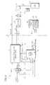
- Fig. 1 is a schematic block diagram of a portion of an elevator motor controller including a current regulator/motor drive having auto-calibration logic, in accordance with the present invention.
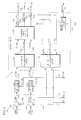
- Fig. 2 is a schematic block diagram of the current regulator/motor drive of Fig. 1, in accordance with the present invention.
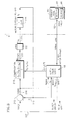
- Fig. 3 is a control system block diagram of system of Fig. 1, in accordance with the present invention.
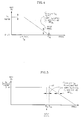
- Fig. 4 is a plot of the magnitude frequency response of the open loop transfer function of the control system of Fig. 3, in accordance with the present invention.
- Fig. 5 is a plot of the magnitude frequency response of the closed loop transfer function of the control system of Fig. 3, in accordance with the present invention.
- Fig. 6 is a logic flow diagram of the auto-calibration logic of Fig. 1, in accordance with the present invention.
- a portion of an elevator motor controller 7 shown to the left of the line 9, includes a field-oriented (or vector-based) motor control that has two control loops each corresponding to a different control axis, a d-axis relating to motor magnetization, and a q-axis relating to torque.
- the d-axis loop has a d-axis current reference input signal I dREF provided on a line 14.
- I dREF is set to a predetermined constant value so as to provide appropriate magnetic flux in the motor based on motor magnetization curves, e.g., I dRATED or I NO-LOAD , discussed more hereinafter.
- the I dREF signal is fed to a field-oriented current regulator/motor drive circuit 20, described more hereinafter with Fig. 2.
- the q-axis current loop has a first q-axis current reference input signal I qREF1 on a line 15 is fed to one input of a switch 19.
- I qREF1 is provided by other logic (not shown), such as speed loop compensation logic (not shown), which closes a motor speed control loop which provides the q-axis current reference signal to the controller when it is not in auto-calibration.
- the other input to the switch 19 is a second q-axis current reference input signal I qREF2 on a line 17.
- the output of the switch 19 is the q-axis current loop reference signal I qREF on a line 18, which is set equal to I qRef1 or I qREF2 based on the state of the MODE1 signal provided to the switch 19 on the line 13.
- the I qREF signal is fed to the field-oriented current regulator/motor drive circuit 20, described more hereinafter with Fig. 2.
- Model LUGA-225LB-04A by Loher, having a rated power of 45KW, rated voltage of 355 volts, rated speed of 1480, and rated frequency of 50 Hz, in a geared configuration
- Model 156MST by Tatung (of Taiwan), having a rated power of 40KW, rated voltage of 500 volts, rated speed of 251, and rated frequency of 16.7 Hz, in a gearless configuration.
- Other motors having other rated parameters may be used if desired.
- the circuit 20 provides three phase voltage signals Vx,Vy,Vz on lines 22 to a motor 24, e.g., a three phase induction motor.
- the motor 24 is connected by a mechanical linkage 26, e.g, a shaft and/or a gearbox, to a sheave 28.
- a rope or cable 30 is wrapped around the sheave 28 and has one end connected to an elevator car 32 and the other end connected to a counterweight 34.
- the weight of the counterweight is typically equal to the weight of an empty car plus 40-50% of the max load in the car.
- elevator system configurations and with or without a counterweight, with or without a gearbox, may be used if desired to convert the output torque of the motor 24 to movement of the elevator cab 32, such as dual lift (where two elevator cars are connected to a single rope, the cars move in opposite directions and each car provides a counterweight for the other car), drum machine (where the rope is wrapped around a drum driven by a motor), etc.
- dual lift where two elevator cars are connected to a single rope, the cars move in opposite directions and each car provides a counterweight for the other car
- drum machine where the rope is wrapped around a drum driven by a motor
- a brake 37 e.g., an electro-magnetic actuated disk brake, is disposed on the shaft 26, and is driven by an electrical brake command signal BRKCMD on a line 38 from the circuit 20.
- the brake 37 when activated or “dropped”, clamps onto the shaft 26 and prevents the motor shaft 26 from turning, i.e., locks the rotor, and thus prevents the sheave 28 from moving.
- the field-oriented current regulator/motor drive 20 of Fig. 1 comprises two current control loops, one for the d-axis current Id and one for q-axis current Iq.
- the Id loop receives the I dREF signal on the line 14 to a positive input to a summer 102.
- a measured or feedback d-axis current signal Id on a line 104 is fed to a negative input to the summer 102.
- the output of the summer 102 is an error signal I dERR on a line 106 which is fed to control compensation logic 108, such as proportional-plus-integral (P-I) current loop control, having a proportional gain K P , an integral gain K I , and an overall gain Gc, provided on lines 121, as described more hereinafter.
- P-I proportional-plus-integral
- the logic 108 provides a d-axis voltage command signal V dCMD on a line 110.
- the Iq loop receives the I qREF signal on the line 18 to a positive input to a summer 114.
- a measured or feedback q-axis current signal Iq on a line 116 is fed to a negative input to the summer 114.
- the output of the summer 114 is an error signal I qERR on a line 118 which is fed to control compensation logic 120, e.g., proportional-plus-integral (P-I) logic similar to the logic 108, having the proportional gain K P , the integral gain K I , and the overall gain Gc, the same as the gains for logic 108.
- the output of the logic 120 is a q-axis voltage command signal V qCMD on a line 122.
- the voltage commands V dCMD and V qCMD are fed to known field-oriented to three-phase conversion logic 124 which converts the d-axis and q-axis voltage commands to three phase voltage commands V XCMD , V YCMD , V ZCMD on lines 126.
- the phase voltage commands V XCMD , V YCMD , V ZCMD are fed to a known three phase drive circuit (or inverter) 128 which provides three phase voltages V X , V Y , V Z on lines 130, 132, 134, respectively (collectively, the lines 22), to drive the motor 24 (Fig. 1).
- each of the voltage commands V XCMD , V YCMD , V ZCMD on lines 126 are converted to percent duty cycle commands indicative of the corresponding input voltage level.
- the percent duty cycle is converted into a pulse-width-modulated drive signal which drives power transistors to provide the pulse-width-modulated, variable frequency, three phase voltages V X , V Y , V Z on lines 130, 132, 134, respectively.
- the conversions within the drive 128 are performed using electronic components and/or software well known in the art of motor drive circuits. Any other type of drive circuit that receives input voltage commands and provides output phase voltages may be used, and the phase voltages need not be pulse-width modulated.
- the phase currents I X , I Y , I Z are fed to known three phase to field-oriented conversion logic 150, which provides a known conversion from phase currents to d axis and q axis currents Id, Iq, on the lines 104,116 which are fed to the summers 102,114, respectively, as feedback currents.
- the converters 124,150 provide known conversions between vector (d and q axis) parameters and per-phase parameters, such as that described in D. Novotny, et al, "Vector Control and Dynamics of AC Drives", Oxford University Press, 1996, Ch 5, pp 203-251.
- the converters 124,150 may likely implement such conversions in software using a microprocessor or the like.
- the motor drive logic 111 also includes a brake drive circuit 145 which receives an input signal BRK on a line 146 and provides a BRKCMD signal on the line 38.
- the present invention comprises auto-calibration logic 48 which automatically computes the control parameters K I , K P , Gc and provides them on the lines 121 to the circuit 20.
- the logic 48 receives I qERR and Iq from the circuit 20.
- the logic 48 also provides the current reference signals I qREF2 to the switch 19 and I dREF to the circuit 20 on the line 14.
- the logic 48 also provides the MODE1 signal on the line 13 to the switch 19.
- the MODE1 flag causes the current reference signal I qREF2 from the calibration logic 48 to be fed to the logic 20.
- the logic 48 also provides a break request signal BRK on the line 146 to the circuit 20.
- the calculation logic 48 also communicates with a service tool 80 over a serial link 82.
- the service tool 80 includes a display 84 and a keypad (or keyboard) 86 for entering data into the service tool 80 and over the link 82 to the controller 7.
- the logic 48 receives a Start command and a Stop command over the link 82 from the service tool 80, which controls when auto-calibration is started and stopped (or aborted), respectively.
- the logic 66 also provides a DONE signal and a FAULT signal to the service tool 80 over the link 82.
- the DONE signal indicates when auto-calibration has completed without any faults and the FAULT signal indicates when a fault has been detected during auto-calibration.
- the logic 48 comprises known electronic components, which may include a microprocessor, interface circuitry, memory, software, and/or firmware, capable of performing the functions described herein.
- a control system block diagram equivalent diagram of the q-axis current loop with the auto-calibration logic 48 of Figs. 1 and 2 is shown when the MODE1 signal (Fig. 1) commands the switch 19 to set I qREF equal to I qREF2 as the reference to the q-axis current loop (i.e., auto-calibration mode).
- the control system of Fig. 3 may be analogized to the portions of the schematic block diagrams of Figs. 1 and 2.
- the control system of Fig. 3 comprises the q-axis current reference signal I qREF on a line 210 (analogous to the line 18 of Fig.
- the compensation 218 comprises a known proportional-plus-integral (P-I) control transfer function: Gc (K P + K I /s) where K I is the integral gain, K P is the proportional gain, Gc is the overall gain, and "s" is the known Laplace transform operator.
- the compensation 218 provides a voltage command signal V qCMD on a line 220 to a box 222 indicative of the transfer function of the motor drive 111 (Fig. 2) which, in the frequency range of interest, has a transfer function of 1.
- the drive 222 provides a per-phase drive voltage Vph on a line 224 to a box 226 representing the transfer function of the motor 24 (Fig. 1).
- the transfer function of the motor 24 is approximated by a first order lag having an equation: 1/(Ls + R) where L is the per-phase inductance of the motor, R is the per-phase resistance of the motor, and "s" is the Laplace transform operator.
- the motor 24 is a three-phase induction motor but may be any type of motor having a similar transfer function.
- the q-axis current Iq of the motor is indicated on a line 214 and is fed back to the summer 212. Iq is actually measured within the drive 111 (Fig. 2); however, the transfer function of the motor is part of the control system loop dynamics as shown in Fig. 3.
- the auto-calibration logic 48 provides I qREF2 to the q-axis current loop on the line 210 (as well as the MODE1 and the I dREF signals, destination not shown in Fig. 3), which in this case, is equal to the q-axis current loop reference I qREF , receives the signals I qERR , Iq on lines 216,214, respectively, (analogous to the lines 118,116 of Fig. 2) from the q-axis current loop, provides the control parameters K I ,K P ,Gc on lines 219 (analogous to lines 121 of Fig. 2) to the compensation 218, and receives and provides parameters over the serial link 82.
- the auto-calibration logic 48 sets Gc and adjusts K I and K P to obtain the desired overall drive/motor loop response without disconnecting or removing the motor.
- the frequency at which the open loop gain crosses through 1 (0 dB), i.e., the open loop cross-over frequency (F OL ) is equal to the frequency at which the closed loop response is less than 1 (0 dB) by a predetermined amount (e.g., 3 dB), i.e., the closed loop bandwidth.
- the auto-calibration logic 48 receives the value of Gc and/or F OL over the link 82 from the service tool 80 (computes Gc or F OL ) and provides Gc to the circuit 20.
- the logic 48 also determines the value of K I and K P using a two-step process (discussed in more detail hereinafter with Fig. 6).
- Other techniques may be used if desired to minimize integrator contribution, such as temporarily disabling the integrator, switching the integrator out of the system, or holding the output of the integrator to zero.
- a sinusoidal input signal is then provided as the reference current I qREF to the loop, where the input signal has a frequency F OL equal to the desired open loop cross-over frequency.
- the open loop magnitude is calculated by calculating the ratio of the signals Iq/I qERR . Kp is varied until the magnitude of the open loop gain is within a predetermined tolerance of 1 (0 dB).
- the open loop response at the open loop crossover frequency resembles that of an integrator. Accordingly, the closed loop bandwidth (indicated by a point 400), i.e., the frequency at which the closed loop frequency response or gain begins to drop off or attenuate, will be substantially equal to the open loop crossover frequency F OL .
- the integral gain K I is tuned with K P set to the value determined from the aforementioned first step.
- Multipliers other than 0.8 may be used if desired based on the desired system response.
- K I is varied until the magnitude of the closed loop transfer function is within a predetermined tolerance of 1 (0dB).
- a top-level flow diagram for the auto-calibration logic 48 begins at a step 300, which checks whether a start command has been received from the service tool 80 (Fig. 1). If a start command has not been received, the logic 48 exits. If a start command has been received, a step 302 requests and receives the necessary parameters to perform auto-calibration, discussed hereinafter.
- I dREF 0.25 x I_BASE
- I_BASE is the motor "base” current calculated from nameplate data as (PWR_RATED)/((3) 1 ⁇ 2 x VLL_RATED).
- Other settings may be used for I dREF if desired, provided the appropriate amount of flux is generated in the motor.
- K P-INIT and I dREF may be calculated by the logic 48 using the nameplate parameters PWR_RATED, RPM_RATED, VLL_RATED, and HZ_RATED, entered into the service tool 80 by service personnel and sent over the link 82 to the logic 48.
- the values of K P-INIT and I dREF may be calculated by service personnel and entered into the service tool 80 and sent over the link 82 to the logic 48.
- a step 310 sets I qREF2 equal to a sinewave having a test frequency of F OL equal to the desired open loop crossover frequency, e.g., 180 to 333 Hz. Other frequencies may be used if desired.
- the sinusoid is generated digitally by a signal processor, such as a digital signal processor, e.g., Motorola DSP 56002 processor, with an update (or sample) rate of 5 KHz. Other hardware and/or software techniques or update rates may be used to generate the sinusoidal input signals.
- a step 312 monitors the signals I qERR and I q on the lines 118, 116, respectively, and uses the aforementioned digital signal processor to perform a Discrete Fourier Transform (DFT) of the individual signals I qERR and I q to obtain the magnitude of the fundamental or first harmonic of the I qERR and I q signals (I qMAG , I qERR-MAG ) to calculate the open loop gain.
- the first harmonic is used to calculate the open loop gain so that non-linearities in the control system do not distort the calculation.
- the fundamental or first harmonic component of a measured signal from a DFT is Asin( ⁇ t) + Bcos( ⁇ t) where ⁇ is the test frequency (2 ⁇ F OL ).
- a step 314 calculates the magnitude of the first harmonic by the known equation: (A 2 + B 2 ) 1/2 .
- any other filtering or spectrum analysis technique may be used for determining the first harmonic of the desired signals.
- a step 316 calculates the open loop gain G OL as the ratio of the magnitude of the current feedback signal I qMAG to the magnitude of the current loop error I qERR-MAG .
- G OL is greater than one
- K P is decremented by a predetermined amount at a step 328. If G OL is less than one, K P is incremented by a predetermined amount at a step 330. In either case, next a step 332 increments the counter COUNT by one and the logic goes to the step 310 to recalculate G OL with a new value of K P .
- KP may be changed by a small amount e.g., 1%, each iteration until the desired tolerance is reached. Any other search techniques that converges within the desired time may be used if desired.
- the integral gain K I is then determined based on the desired closed loop frequency response to a sinusoidal input frequency.
- the sinusoid is generated as described hereinbefore with the open loop test of step 310.
- a step 344 monitors the feedback current signal Iq on the lines 116 and computes the discrete Fourier transform (DFT) of the signal Iq to obtain the magnitude of the fundamental or first harmonic of the Iq signal (I qMAG ) used to calculate the closed loop gain so that non-linearities in the control system do not distort the calculation, in a similar fashion to that done for the open loop gain discussed hereinbefore.
- a step 346 calculates the magnitude of the first harmonic by the known equation: (A 2 + B 2 ) 1/2 .
- the number of integration periods for the DFT are the same as that discussed hereinbefore.
- a step 348 calculates the closed loop gain G CL as the ratio of the magnitude of the current feedback signal I qMAG to the magnitude of the input current loop reference signal I qMAG (which was provided by the logic 48, and thus need not be measured).
- K I is incremented by a predetermined amount at a step 358. In either case, next a step 362 increments the counter COUNT by one and the logic goes to the step 342 to recalculate G CL with a new value of K I .
- K I may be changed by a small amount e.g., 1%, each iteration until the desired tolerance is reached. Any other search or iteration techniques that converges within the desired time may be used if desired.
Applications Claiming Priority (2)
| Application Number | Priority Date | Filing Date | Title |
|---|---|---|---|
| US996234 | 1997-12-22 | ||
| US08/996,234 US5880415A (en) | 1997-12-22 | 1997-12-22 | Automatic calibration of current regulator control compensation for an elevator motor drive with locked rotor |
Publications (3)
| Publication Number | Publication Date |
|---|---|
| EP0924850A2 true EP0924850A2 (de) | 1999-06-23 |
| EP0924850A3 EP0924850A3 (de) | 2000-05-10 |
| EP0924850B1 EP0924850B1 (de) | 2006-06-07 |
Family
ID=25542657
Family Applications (1)
| Application Number | Title | Priority Date | Filing Date |
|---|---|---|---|
| EP98310406A Expired - Lifetime EP0924850B1 (de) | 1997-12-22 | 1998-12-18 | Automatische Kalibrierung der Stromregler-Kompensation eines Aufzugmotorantriebs mit blockiertem Rotor |
Country Status (5)
| Country | Link |
|---|---|
| US (1) | US5880415A (de) |
| EP (1) | EP0924850B1 (de) |
| JP (1) | JP4189071B2 (de) |
| CN (1) | CN1145577C (de) |
| DE (1) | DE69834798T2 (de) |
Cited By (7)
| Publication number | Priority date | Publication date | Assignee | Title |
|---|---|---|---|---|
| EP0924852A2 (de) * | 1997-12-22 | 1999-06-23 | Otis Elevator Company | Automatische Kalibrierung der Parameter eines feldorietierten Aufzugmotorantriebs unter Verwendung von Messungen im Motorstillstand |
| EP0924851A2 (de) * | 1997-12-22 | 1999-06-23 | Otis Elevator Company | Automatische Feinabstimmung der Rotorzeitkonstanten und des Magnetisierungsstromes in feldorientierten Aufzugsmotorantrieben |
| EP0933869A2 (de) * | 1997-12-22 | 1999-08-04 | Otis Elevator Company | Automatische Feinabstimmung der Rotorzeitkonstante für eine feldorientierten Aufzugsantriebsmotor |
| EP0936730A2 (de) * | 1997-12-22 | 1999-08-18 | Otis Elevator Company | Selbsttätiger Inbetriebnahmeregler für ein feldorientiertes Aufzugsmotorantriebssystem |
| EP1696556A2 (de) * | 2005-02-23 | 2006-08-30 | Certance LLC | Vorspannungs-Kalibrierung eines Stromregelkreises durch Integration |
| JP2013201803A (ja) * | 2012-03-23 | 2013-10-03 | Mori Seiki Co Ltd | 同期モータの制御装置、同期モータの制御方法 |
| WO2017036509A1 (en) * | 2015-08-31 | 2017-03-09 | Otis Elevator Company | Conveyor drive unit with initialization of the adaptive power supply unit and identification of the motor |
Families Citing this family (23)
| Publication number | Priority date | Publication date | Assignee | Title |
|---|---|---|---|---|
| JP3291224B2 (ja) * | 1997-06-30 | 2002-06-10 | オークマ株式会社 | 速度制御装置 |
| DE19734208A1 (de) * | 1997-08-07 | 1999-02-11 | Heidenhain Gmbh Dr Johannes | Verfahren und Schaltungsanordnung zur Ermittlung optimaler Reglerparamter für eine Drehzahlregelung |
| US6711556B1 (en) | 1999-09-30 | 2004-03-23 | Ford Global Technologies, Llc | Fuzzy logic controller optimization |
| US6452360B1 (en) | 1999-12-03 | 2002-09-17 | Square D. Company | Auto tuning and parameter identification of a control circuit |
| US6622099B2 (en) * | 2000-08-14 | 2003-09-16 | Kollmorgen Corporation | Frequency domain auto-tune for an internal motor controller |
| JP4146141B2 (ja) * | 2002-03-12 | 2008-09-03 | 東芝エレベータ株式会社 | 振動調整装置および振動調整方法 |
| US6895352B2 (en) * | 2002-03-12 | 2005-05-17 | Itt Manufacturing Enterprises, Inc. | Simultaneous rapid open and closed loop bode plot measurement using a binary pseudo-random sequence |
| US6838852B1 (en) | 2003-04-01 | 2005-01-04 | General Motors Corporation | Plug and play electric machine |
| JP4704182B2 (ja) * | 2005-10-20 | 2011-06-15 | 台達電子工業股▲ふん▼有限公司 | 電流センサレス交流サーボ駆動装置 |
| CN101707465B (zh) * | 2009-11-10 | 2012-05-30 | 深圳市雷赛机电技术开发有限公司 | 电机电流环参数整定方法 |
| US8587233B2 (en) | 2010-01-25 | 2013-11-19 | Sntech, Inc. | Speed-defined torque control |
| US8965538B2 (en) * | 2010-05-19 | 2015-02-24 | The Boeing Company | Methods and apparatus for state limiting in a control system |
| US8942942B2 (en) | 2010-07-23 | 2015-01-27 | Caterpillar Inc. | Generator set calibration controller |
| US8478550B2 (en) * | 2010-07-23 | 2013-07-02 | Caterpillar Inc. | Generator set calibration controller |
| TW201230657A (en) * | 2010-10-08 | 2012-07-16 | Panasonic Corp | Current control gain adjusting method for pm motor, current control method, and control device |
| JP5888567B2 (ja) * | 2014-02-12 | 2016-03-22 | 株式会社デンソー | 交流電動機の制御装置 |
| US9618582B2 (en) | 2014-10-30 | 2017-04-11 | Delphi Technologies, Inc. | System and method of electric motor fault detection |
| JP6106226B2 (ja) * | 2015-07-31 | 2017-03-29 | ファナック株式会社 | ゲインの最適化を学習する機械学習装置及び機械学習装置を備えた電動機制御装置並びに機械学習方法 |
| FR3066276B1 (fr) * | 2017-05-10 | 2019-04-26 | Schneider Toshiba Inverter Europe Sas | Procede d'identification de la resistance electrique du rotor d'un moteur electrique |
| US11482942B2 (en) | 2017-10-31 | 2022-10-25 | Otis Elevator Company | Single phase operation of three phase regenerative drives |
| CN108657893B (zh) * | 2018-05-28 | 2020-07-28 | 苏州汇川技术有限公司 | 一种电梯救援方法、系统以及控制器 |
| CN111913104B (zh) | 2019-05-08 | 2023-01-13 | 博格华纳公司 | 用于电动马达的调试过程中确定马达参数的方法 |
| TW202206952A (zh) * | 2020-08-07 | 2022-02-16 | 永大機電工業股份有限公司 | 決定電梯速度控制係數的方法 |
Citations (7)
| Publication number | Priority date | Publication date | Assignee | Title |
|---|---|---|---|---|
| US5223778A (en) * | 1992-09-16 | 1993-06-29 | Allen-Bradley Company, Inc. | Automatic tuning apparatus for PID controllers |
| US5476158A (en) * | 1993-03-31 | 1995-12-19 | Otis Elevator Company | Rotor time constant adaptation for induction motor in vector controlled elevator drive |
| FR2731568A1 (fr) * | 1995-03-09 | 1996-09-13 | Alsthom Cge Alcatel | Correcteur, dispositif et procede pour la commande du couple electromagnetique d'une machine asynchrone |
| EP0924852A2 (de) * | 1997-12-22 | 1999-06-23 | Otis Elevator Company | Automatische Kalibrierung der Parameter eines feldorietierten Aufzugmotorantriebs unter Verwendung von Messungen im Motorstillstand |
| EP0924851A2 (de) * | 1997-12-22 | 1999-06-23 | Otis Elevator Company | Automatische Feinabstimmung der Rotorzeitkonstanten und des Magnetisierungsstromes in feldorientierten Aufzugsmotorantrieben |
| EP0933869A2 (de) * | 1997-12-22 | 1999-08-04 | Otis Elevator Company | Automatische Feinabstimmung der Rotorzeitkonstante für eine feldorientierten Aufzugsantriebsmotor |
| EP0936730A2 (de) * | 1997-12-22 | 1999-08-18 | Otis Elevator Company | Selbsttätiger Inbetriebnahmeregler für ein feldorientiertes Aufzugsmotorantriebssystem |
-
1997
- 1997-12-22 US US08/996,234 patent/US5880415A/en not_active Expired - Lifetime
-
1998
- 1998-12-17 JP JP35876498A patent/JP4189071B2/ja not_active Expired - Lifetime
- 1998-12-18 EP EP98310406A patent/EP0924850B1/de not_active Expired - Lifetime
- 1998-12-18 DE DE69834798T patent/DE69834798T2/de not_active Expired - Lifetime
- 1998-12-21 CN CNB981255310A patent/CN1145577C/zh not_active Expired - Fee Related
Patent Citations (7)
| Publication number | Priority date | Publication date | Assignee | Title |
|---|---|---|---|---|
| US5223778A (en) * | 1992-09-16 | 1993-06-29 | Allen-Bradley Company, Inc. | Automatic tuning apparatus for PID controllers |
| US5476158A (en) * | 1993-03-31 | 1995-12-19 | Otis Elevator Company | Rotor time constant adaptation for induction motor in vector controlled elevator drive |
| FR2731568A1 (fr) * | 1995-03-09 | 1996-09-13 | Alsthom Cge Alcatel | Correcteur, dispositif et procede pour la commande du couple electromagnetique d'une machine asynchrone |
| EP0924852A2 (de) * | 1997-12-22 | 1999-06-23 | Otis Elevator Company | Automatische Kalibrierung der Parameter eines feldorietierten Aufzugmotorantriebs unter Verwendung von Messungen im Motorstillstand |
| EP0924851A2 (de) * | 1997-12-22 | 1999-06-23 | Otis Elevator Company | Automatische Feinabstimmung der Rotorzeitkonstanten und des Magnetisierungsstromes in feldorientierten Aufzugsmotorantrieben |
| EP0933869A2 (de) * | 1997-12-22 | 1999-08-04 | Otis Elevator Company | Automatische Feinabstimmung der Rotorzeitkonstante für eine feldorientierten Aufzugsantriebsmotor |
| EP0936730A2 (de) * | 1997-12-22 | 1999-08-18 | Otis Elevator Company | Selbsttätiger Inbetriebnahmeregler für ein feldorientiertes Aufzugsmotorantriebssystem |
Non-Patent Citations (4)
| Title |
|---|
| H.SCHIERLING : "SELF-COMMISSIONING -A NOVEL FEATURE OF MODERN INVERTER-FED INDUCTION MOTOR DRIVES" IEEE PROCEEDINGS , vol. 140, no. 3, May 1993 (1993-05), pages 287-290, XP000892216 * |
| K.TUNGPIMORLUT ET AL: "A DIRECT METHOD OF MACHINE PARAMETERS FOR VECTROR-CONTROLLED INDUCTION MOTOR DRIVES" IEEE,1993, pages 997-1002, XP000892218 * |
| T.KUDOR ET AL: "SELF-COMMISSIONING FOR VECTRO CONTROLLED INDUCTION MOTORS" IEEE,1993, pages 528-535, XP000892215 * |
| T.ROWAN ET AL: "A SIMPLE ON-LINE ADAPTATION FOR INDIRECT FIELD ORIENTATION OF AN INDUCTION MACHINE" IEEE TRANSACTIONS ON INDUSTRY APPLICATIONS, vol. 27, no. 4, August 1991 (1991-08), pages 720-727, XP000892217 * |
Cited By (14)
| Publication number | Priority date | Publication date | Assignee | Title |
|---|---|---|---|---|
| EP0924852B1 (de) * | 1997-12-22 | 2007-02-14 | Otis Elevator Company | Automatische Kalibrierung der Parameter eines feldorientierten Aufzugmotorantriebs unter Verwendung von Messungen im Motorstillstand |
| EP0924851A2 (de) * | 1997-12-22 | 1999-06-23 | Otis Elevator Company | Automatische Feinabstimmung der Rotorzeitkonstanten und des Magnetisierungsstromes in feldorientierten Aufzugsmotorantrieben |
| EP0933869A2 (de) * | 1997-12-22 | 1999-08-04 | Otis Elevator Company | Automatische Feinabstimmung der Rotorzeitkonstante für eine feldorientierten Aufzugsantriebsmotor |
| EP0936730A2 (de) * | 1997-12-22 | 1999-08-18 | Otis Elevator Company | Selbsttätiger Inbetriebnahmeregler für ein feldorientiertes Aufzugsmotorantriebssystem |
| EP0936730B1 (de) * | 1997-12-22 | 2006-06-21 | Otis Elevator Company | Selbsttätiger Inbetriebnahmeregler für ein feldorientiertes Aufzugsmotorantriebssystem |
| EP0933869B1 (de) * | 1997-12-22 | 2006-06-21 | Otis Elevator Company | Automatische Feinabstimmung der Rotorzeitkonstante für eine feldorientierten Aufzugsantriebsmotor |
| EP0924852A2 (de) * | 1997-12-22 | 1999-06-23 | Otis Elevator Company | Automatische Kalibrierung der Parameter eines feldorietierten Aufzugmotorantriebs unter Verwendung von Messungen im Motorstillstand |
| EP0924851B1 (de) * | 1997-12-22 | 2006-08-30 | Otis Elevator Company | Automatische Feinabstimmung der Rotorzeitkonstanten und des Magnetisierungsstromes in feldorientierten Aufzugsmotorantrieben |
| EP1696556A2 (de) * | 2005-02-23 | 2006-08-30 | Certance LLC | Vorspannungs-Kalibrierung eines Stromregelkreises durch Integration |
| EP1696556A3 (de) * | 2005-02-23 | 2007-02-14 | Certance LLC | Vorspannungs-Kalibrierung eines Stromregelkreises durch Integration |
| JP2013201803A (ja) * | 2012-03-23 | 2013-10-03 | Mori Seiki Co Ltd | 同期モータの制御装置、同期モータの制御方法 |
| WO2017036509A1 (en) * | 2015-08-31 | 2017-03-09 | Otis Elevator Company | Conveyor drive unit with initialization of the adaptive power supply unit and identification of the motor |
| CN107922169A (zh) * | 2015-08-31 | 2018-04-17 | 奥的斯电梯公司 | 具有自适应电源单元的初始化和电动机的识别的输送机驱动单元 |
| US10399823B2 (en) | 2015-08-31 | 2019-09-03 | Otis Elevator Company | Conveyor drive unit with initialization of the adaptive power supply unit and identification of the motor |
Also Published As
| Publication number | Publication date |
|---|---|
| JP4189071B2 (ja) | 2008-12-03 |
| CN1145577C (zh) | 2004-04-14 |
| DE69834798T2 (de) | 2007-06-06 |
| DE69834798D1 (de) | 2006-07-20 |
| US5880415A (en) | 1999-03-09 |
| EP0924850B1 (de) | 2006-06-07 |
| EP0924850A3 (de) | 2000-05-10 |
| JPH11252964A (ja) | 1999-09-17 |
| CN1229761A (zh) | 1999-09-29 |
Similar Documents
| Publication | Publication Date | Title |
|---|---|---|
| US5880415A (en) | Automatic calibration of current regulator control compensation for an elevator motor drive with locked rotor | |
| US5883344A (en) | Automatic calibration of field-oriented elevator motor drive parameters using standstill motor measurements | |
| EP0936730B1 (de) | Selbsttätiger Inbetriebnahmeregler für ein feldorientiertes Aufzugsmotorantriebssystem | |
| JP4160676B2 (ja) | 界磁有向性エレベータモータ駆動における回転子時定数と磁化電流の自動微同調 | |
| US6262555B1 (en) | Apparatus and method to generate braking torque in an AC drive | |
| US8169172B2 (en) | Synchronous disturbance suppression in a variable speed motor drive | |
| EP1833153B1 (de) | Elektrisches Motorenstartsystem mit aktivem Gleichrichter | |
| US5998958A (en) | Method for estimating resistance values of stator and rotor of induction motor | |
| CA2017074C (en) | Frequency control based on sensing voltage fed to an induction motor | |
| EP2865889B1 (de) | Dämpfung der Schwingungen eines Windturbinenantriebsstrangs | |
| US10100811B2 (en) | Noise control for a wind turbine | |
| US4437051A (en) | Method and apparatus for controlling induction motor | |
| US5880416A (en) | Automatic calibration of motor speed loop gain for an elevator motor control | |
| US5896954A (en) | Automatic fine tuning of rotor time constant in field-oriented elevator motor drive | |
| US6166928A (en) | Method for open-loop and closed-loop control of an electrical drive as well as an apparatus for carrying out the method | |
| EP3282538A1 (de) | System und verfahren zur steuerung von negativsequenzstrom in einem windturbinengenerator | |
| JP4160675B2 (ja) | 界磁有向性エレベータモータ駆動における回転子時定数と磁化電流の自動微同調 | |
| JPH09235079A (ja) | 直流エレベータの制御装置 |
Legal Events
| Date | Code | Title | Description |
|---|---|---|---|
| PUAI | Public reference made under article 153(3) epc to a published international application that has entered the european phase |
Free format text: ORIGINAL CODE: 0009012 |
|
| AK | Designated contracting states |
Kind code of ref document: A2 Designated state(s): DE FR GB |
|
| AX | Request for extension of the european patent |
Free format text: AL;LT;LV;MK;RO;SI |
|
| PUAL | Search report despatched |
Free format text: ORIGINAL CODE: 0009013 |
|
| AK | Designated contracting states |
Kind code of ref document: A3 Designated state(s): AT BE CH CY DE DK ES FI FR GB GR IE IT LI LU MC NL PT SE |
|
| AX | Request for extension of the european patent |
Free format text: AL;LT;LV;MK;RO;SI |
|
| RIC1 | Information provided on ipc code assigned before grant |
Free format text: 7H 02P 21/00 A, 7B 66B 1/28 B, 7G 05B 11/32 B, 7G 05B 23/02 B |
|
| 17P | Request for examination filed |
Effective date: 20000613 |
|
| AKX | Designation fees paid |
Free format text: DE FR GB |
|
| GRAP | Despatch of communication of intention to grant a patent |
Free format text: ORIGINAL CODE: EPIDOSNIGR1 |
|
| GRAS | Grant fee paid |
Free format text: ORIGINAL CODE: EPIDOSNIGR3 |
|
| GRAA | (expected) grant |
Free format text: ORIGINAL CODE: 0009210 |
|
| AK | Designated contracting states |
Kind code of ref document: B1 Designated state(s): DE FR GB |
|
| REG | Reference to a national code |
Ref country code: GB Ref legal event code: FG4D |
|
| REF | Corresponds to: |
Ref document number: 69834798 Country of ref document: DE Date of ref document: 20060720 Kind code of ref document: P |
|
| ET | Fr: translation filed | ||
| PLBE | No opposition filed within time limit |
Free format text: ORIGINAL CODE: 0009261 |
|
| STAA | Information on the status of an ep patent application or granted ep patent |
Free format text: STATUS: NO OPPOSITION FILED WITHIN TIME LIMIT |
|
| 26N | No opposition filed |
Effective date: 20070308 |
|
| PGFP | Annual fee paid to national office [announced via postgrant information from national office to epo] |
Ref country code: GB Payment date: 20141217 Year of fee payment: 17 |
|
| REG | Reference to a national code |
Ref country code: FR Ref legal event code: PLFP Year of fee payment: 18 |
|
| GBPC | Gb: european patent ceased through non-payment of renewal fee |
Effective date: 20151218 |
|
| PG25 | Lapsed in a contracting state [announced via postgrant information from national office to epo] |
Ref country code: GB Free format text: LAPSE BECAUSE OF NON-PAYMENT OF DUE FEES Effective date: 20151218 |
|
| REG | Reference to a national code |
Ref country code: FR Ref legal event code: PLFP Year of fee payment: 19 |
|
| PGFP | Annual fee paid to national office [announced via postgrant information from national office to epo] |
Ref country code: FR Payment date: 20161121 Year of fee payment: 19 Ref country code: DE Payment date: 20161121 Year of fee payment: 19 |
|
| REG | Reference to a national code |
Ref country code: DE Ref legal event code: R082 Ref document number: 69834798 Country of ref document: DE Representative=s name: SCHMITT-NILSON SCHRAUD WAIBEL WOHLFROM PATENTA, DE |
|
| REG | Reference to a national code |
Ref country code: DE Ref legal event code: R119 Ref document number: 69834798 Country of ref document: DE |
|
| REG | Reference to a national code |
Ref country code: FR Ref legal event code: ST Effective date: 20180831 |
|
| PG25 | Lapsed in a contracting state [announced via postgrant information from national office to epo] |
Ref country code: FR Free format text: LAPSE BECAUSE OF NON-PAYMENT OF DUE FEES Effective date: 20180102 Ref country code: DE Free format text: LAPSE BECAUSE OF NON-PAYMENT OF DUE FEES Effective date: 20180703 |