EP0924467B1 - Einrichtung zur Betriebssteuerung eines Haushaltbrenners mittels Flammendetektion - Google Patents
Einrichtung zur Betriebssteuerung eines Haushaltbrenners mittels Flammendetektion Download PDFInfo
- Publication number
- EP0924467B1 EP0924467B1 EP98403165A EP98403165A EP0924467B1 EP 0924467 B1 EP0924467 B1 EP 0924467B1 EP 98403165 A EP98403165 A EP 98403165A EP 98403165 A EP98403165 A EP 98403165A EP 0924467 B1 EP0924467 B1 EP 0924467B1
- Authority
- EP
- European Patent Office
- Prior art keywords
- signal
- flame
- burner
- com
- box
- Prior art date
- Legal status (The legal status is an assumption and is not a legal conclusion. Google has not performed a legal analysis and makes no representation as to the accuracy of the status listed.)
- Expired - Lifetime
Links
- 238000001514 detection method Methods 0.000 claims description 25
- 230000008034 disappearance Effects 0.000 claims description 9
- 230000000903 blocking effect Effects 0.000 claims description 7
- 230000007423 decrease Effects 0.000 claims description 7
- 238000002485 combustion reaction Methods 0.000 claims description 4
- 230000002159 abnormal effect Effects 0.000 claims description 2
- 230000003247 decreasing effect Effects 0.000 claims description 2
- 230000008033 biological extinction Effects 0.000 description 14
- 238000010586 diagram Methods 0.000 description 12
- 230000009471 action Effects 0.000 description 3
- 230000004913 activation Effects 0.000 description 3
- 230000008901 benefit Effects 0.000 description 2
- 238000006073 displacement reaction Methods 0.000 description 2
- 238000010438 heat treatment Methods 0.000 description 2
- 239000007788 liquid Substances 0.000 description 2
- 239000012528 membrane Substances 0.000 description 2
- 229910052751 metal Inorganic materials 0.000 description 2
- 239000002184 metal Substances 0.000 description 2
- 150000002739 metals Chemical class 0.000 description 2
- 238000000034 method Methods 0.000 description 2
- 230000008569 process Effects 0.000 description 2
- 230000004044 response Effects 0.000 description 2
- 230000009849 deactivation Effects 0.000 description 1
- 239000000446 fuel Substances 0.000 description 1
- 239000000203 mixture Substances 0.000 description 1
- 231100000331 toxic Toxicity 0.000 description 1
- 230000002588 toxic effect Effects 0.000 description 1
- 230000001960 triggered effect Effects 0.000 description 1
Images

Classifications
-
- F—MECHANICAL ENGINEERING; LIGHTING; HEATING; WEAPONS; BLASTING
- F23—COMBUSTION APPARATUS; COMBUSTION PROCESSES
- F23N—REGULATING OR CONTROLLING COMBUSTION
- F23N5/00—Systems for controlling combustion
- F23N5/02—Systems for controlling combustion using devices responsive to thermal changes or to thermal expansion of a medium
- F23N5/10—Systems for controlling combustion using devices responsive to thermal changes or to thermal expansion of a medium using thermocouples
- F23N5/102—Systems for controlling combustion using devices responsive to thermal changes or to thermal expansion of a medium using thermocouples using electronic means
-
- F—MECHANICAL ENGINEERING; LIGHTING; HEATING; WEAPONS; BLASTING
- F23—COMBUSTION APPARATUS; COMBUSTION PROCESSES
- F23N—REGULATING OR CONTROLLING COMBUSTION
- F23N2223/00—Signal processing; Details thereof
- F23N2223/14—Differentiation
-
- F—MECHANICAL ENGINEERING; LIGHTING; HEATING; WEAPONS; BLASTING
- F23—COMBUSTION APPARATUS; COMBUSTION PROCESSES
- F23N—REGULATING OR CONTROLLING COMBUSTION
- F23N2227/00—Ignition or checking
- F23N2227/36—Spark ignition, e.g. by means of a high voltage
-
- F—MECHANICAL ENGINEERING; LIGHTING; HEATING; WEAPONS; BLASTING
- F23—COMBUSTION APPARATUS; COMBUSTION PROCESSES
- F23N—REGULATING OR CONTROLLING COMBUSTION
- F23N2231/00—Fail safe
- F23N2231/20—Warning devices
-
- F—MECHANICAL ENGINEERING; LIGHTING; HEATING; WEAPONS; BLASTING
- F23—COMBUSTION APPARATUS; COMBUSTION PROCESSES
- F23N—REGULATING OR CONTROLLING COMBUSTION
- F23N2235/00—Valves, nozzles or pumps
- F23N2235/12—Fuel valves
- F23N2235/14—Fuel valves electromagnetically operated
Definitions
- the invention relates to a device for assisting in the management of operation of a domestic burner by flame detection for any type of gas fuel burner present on the appliances gas-powered domestic appliances such as gas stoves gas, gas ovens, hobs.
- the burners are the parts of the appliance where the combustion of the mixture between the combustible gas and the air. Some burners are fitted with a device to detect the presence flame and activate the opening and closing of a valve gas inlet. This in particular constitutes security in the event of accidental extinction of the flame which may cause a gas leak toxic, for example as a result of a strong draft or liquid spilling onto the flame.
- the most detection device current on household burners includes a thermocouple positioned at the level of the flame and an electromagnet which actuates a core for shutting off the gas supply. When the flame is present, the thermocouple heats up, delivering a current which feeds the electromagnet.
- the catch current Beyond a certain threshold, called the catch current, the core is attracted to a position which allows the circulation of gas. At otherwise, if the flame goes out, the current delivered by the thermocouple decreases and when it becomes lower than the catch current, the nucleus deviates, for example by the action of a spring, and closes the arrival of gas.
- These devices are simple, space-saving, easy to implement and extremely widespread. Their main drawback is however their inertia both at the time of lighting the flame that at the time of its extinction. It takes several seconds to that in the presence of the flame, the current reaches the current hooking; this therefore requires keeping a valve open gas supply, for example by manual control, during this duration.
- the device according to the invention provides electronic processing the signal delivered by the thermocouple which makes it possible to detect the presence flame when it appeared, as well as when it went out, with independent time constants.
- the burner can thus be activated, with adequate means, at predetermined times independently of each other with respect to the moments of appearance or disappearance of the flame.
- the invention consists of a device for assisting in the management of the operation of a domestic gas burner, comprising a thermocouple positioned in the vicinity of the flame resulting from the combustion of the gas and delivering an electrical signal s tc function of the local temperature, means for actuating the burner and a control box, the box processing the electrical signal s tc in order to control said means, characterized in that the box comprises means making it possible to define a second signal, originating from the signal s tc delivered by the thermocouple, and means for processing these two signals making it possible to detect the presence of the flame in order to actuate the burner at predetermined times independently of one another with respect to the moments of appearance or disappearance of the flame.
- the actuating means can comprise for example a electro-mechanical actuator of a gas inlet valve or a burner ignition device.
- the invention makes it possible to control the inertia of the detection device while using standard thermocouples; the device according to the invention is therefore easily adaptable to existing burners. It allows to detect with independent time constants the appearance and the disappearance of the flame.
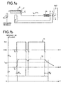
- FIG. 1a schematically represents an example of a flame detection device according to the prior art for controlling a valve V for the arrival of gas in a burner B.
- the device comprises a thermocouple TC positioned in the vicinity of the resulting flame F of the combustion of the gas in burner B.
- the thermocouple is composed of two different metals and placed so that the junction points between the metals are brought to different temperatures in the presence of the flame F. This temperature difference is at the origin of the electrical signal delivered by the thermocouple. In known devices, it is the current i tc delivered by the thermocouple which is used to supply an electromagnet EA symbolized in FIG. 1a by a coil.
- the device described in FIG. 1 a further comprises an ALL ignition device for the burner B, triggered manually, which can operate, for example, by the emission of a train of electrical pulses or by heating near the burner. a glowing wire.
- Figure 1b illustrates an operating mode of such a device.
- the curve 11 represents as a function of the time noted t the presence (noted YES in the figure) or the absence (noted NO) of the flame F.
- the instant t 0 represents the moment when the ignition device is actuated . This action is maintained until time t 1 of appearance of the flame.
- the valve V is kept open by means different from those used in the device based on the detection of the flame. These means are here called external means. It may for example be a manual control.
- Curve 11 also shows between instants t 2 and t 3 , a momentary and partial extinction of the flame, for example due to the spillage of a liquid on a zone of the flame close to the thermocouple and sufficiently small so that the flame can switch on completely and quickly. Finally the instant t 4 corresponds to the disappearance of the flame.
- Curve 12 gives, as a function of time t, the current i tc delivered by the thermocouple during the same period as that represented by curve 11.
- a certain period of time ⁇ t m is necessary for the device based on the flame detection to take over from the external means to allow the opening of the valve V.
- the detection of the presence of the flame which results here by the opening of the valve thanks to the device is represented in FIG. 1b by a quantity Y taking as value 1.
- the latching current can be reduced to reduce the time ⁇ t m .
- the time ⁇ t d here called the descent time or extinction detection time, necessary for the current i tc to become lower than the threshold i acc and therefore that the core N come close the valve V will only be larger; in FIG. 1b, the detection of the extinction of the flame, resulting in the closing of the valve by means of the device is represented by the quantity Y taking the value 0.
- the descent time ⁇ t d is typically a few tens of seconds. It can be seen from this example that the times of detection of presence or extinction of the flame are linked. Between instants t 2 and t 3 , corresponding to a momentary extinction of the flame, if this period of time is sufficiently short, the current i tc has not fallen below the threshold i acc and the valve therefore remains open, this which is an advantage of the inertia of such a device.
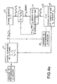
- thermocouple TC which can be the same as those used in the devices of the prior art.
- the TC thermocouple when subjected to a temperature variation delivers an electrical signal s tc .
- the device further comprises means MA for actuating the burner B and a control unit COM.
- the COM box processes the signal s tc in order to control the means MA which allow the burner to start when they are activated.
- the actuation means MA of the burner may include, as illustrated in FIG. 2, an electromechanical actuator AEM allowing the opening or closing of a valve V for the arrival of gas in the burner.
- the COM box processes the signal s tc in order to control the AEM actuator to trigger the opening or closing of the valve V.
- the electromechanical actuator AEM can include an electromagnet of the same type as those used in the devices of the prior art, but controlled in this case by the COM control unit.
- Other types of actuators can be used in the device according to the invention.
- the actuator may include a piezoelectric device which allows, under the action of an electrical signal, the displacement of a membrane; this membrane coming for example to shut off the gas supply at the level of the valve V. Note that a piezoelectric device requires high supply voltages to obtain small displacements, also such an actuator would have been difficult to envisage in a device of the prior art.
- the means MA can also include a device ALL ignition of the burner, the COM control unit allowing control the switching on or off of the ignition device.
- the ignition device can for example as in some devices of the prior art operate by the emission of a train of pulses electric or by heating near the burner of a wire incandescent.
- the processing functions performed by the housing COM are such that the activation or deactivation of the means MA can be determined independently with respect to the moments of appearance or disappearance of the flame F.
- the housing COM of the device according to the invention comprises means making it possible to define a second signal, originating from the signal s tc delivered by the thermocouple. It further comprises means for processing these two signals making it possible to detect the presence of the flame in order to actuate the burner B at predetermined times independently of one another with respect to the moments of appearance or disappearance of flame F.
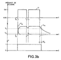
- FIG. 3a An example of such an operating mode of the COM control unit is shown in FIG. 3a.
- the means making it possible to define the second signal are means 31 for calculating the derivative s' tc of the electrical signal s tc delivered by the thermocouple.
- the means for processing the two signals comprise means 32 for comparing the signal s tc with a first threshold value s 1 and means for comparing the derivative s' tc with a second threshold value s 2 . The results of these comparisons are called A 1 and A 2 respectively. For example, A 1 is worth 1 if s tc is greater than or equal to s 1 and A 2 is worth 1 if s' tc is greater than or equal to s 2 . A 1 and A 2 are worth 0 otherwise.
- the processing means also include means 34 making it possible to operate a logic function between the quantities A 1 and A 2 .
- this function is a logical OR.
- the result of this operation is the quantity Y which materializes the flame detection.
- Y equals 1 when the presence of the flame is detected, Y equals 0 otherwise.
- the value of Y determines the activation of the actuation means MA of the burner.
- t 1 of appearance of the flame it is for example the value of s' tc which determines the detection of the flame; we set a threshold value s 2 strictly positive, so that upon ignition of the flame, the variation of heat at the thermocouple almost instantly causes the relationship s' tc greater than or equal to s 2 , the quantity A 2 taking the value 1; it follows that the result Y of the operation between A 1 and A 2 also changes to 1, which causes the detection of the flame and therefore the control of the actuation means MA of the burner B with a rise time ⁇ t m close to 0. In the example chosen, this results in the opening of the valve V thanks to the electro-mechanical actuator AEM and the automatic shutdown of the ignition device ALL also controlled by the box COM.
- s 1 can be chosen so that, when s' tc is less than s 2 , s tc is greater than s 1, causing the passage to 1 of the quantity A 1 .
- Y is always equal to 1.
- the choice of s 1 thus determines the descent time ⁇ t d ; it is then necessary to find a compromise on the value of s 1 to reduce the descent time ⁇ t d while fixing a duration (corresponding on curve 11 to the period between the instants t 2 and t 3 ) during which the flame can locally and momentarily turn off without causing the valve V to close or the ignition device to restart; typically, ⁇ t d is worth a few seconds.
- the threshold s 1 is advantageously fixed as a function of the family of thermocouples used in order to have a similar response for all of the thermocouples.
- the functions performed by the COM box can be performed by means of electronic analog or digital functions, by means of software programmed for example on a microcontroller.
- the electrical signal s tc delivered by the thermocouple TC and processed by the control unit COM is for example the voltage measured at the terminals of the thermocouple. This makes the operation of the device more reliable because the signal is then independent of the values of the resistance of electrical connections.
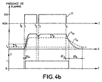
- the means making it possible to define the second signal are means making it possible to construct from the electrical signal s tc delivered by the thermocouple TC a signal r tc (in dotted lines in FIG. 4b) and the means for processing the two signals comprise means for comparing the signal s tc and the signal r tc .
- the result Y of the comparison makes it possible to determine the detection of the presence of the flame. It is then transmitted to the actuation means MA of the burner to control their activation. In the example chosen, the detection of the presence of the flame, corresponding to Y 1 in FIG.
- the quantity Y is sent to the actuating means which can be, to use the previous example, the electromechanical actuator AEM of the valve V and the ignition device ALL.
- the signal r tc can for example be constructed as follows.
- the signal s tc begins to increase; when s tc becomes greater than r tc (42), Y goes to 1 and the flame presence detection is obtained with a rise time ⁇ t m which therefore depends on the minimum value r s .
- This rise time can be of the order of a second.
- the signal r tc is equal to the difference of the signal s tc and an offset value s g .
- the threshold value can be equal to the offset value, as is substantially the case in Figure 4b.
- the signal r tc decreases with a predetermined time constant, this constant being greater than that of decrease of the signal s tc . If s tc increases again before s tc has become less than r tc , r tc takes the value equal to the difference of the signal s tc and the offset value s g .
- the value Y can be maintained at 0 for a duration ⁇ t b (blocking period 46) corresponding to the time it takes for the signal r tc to decrease to the minimum value r s .
- the blocking period allows, when a new appearance of the flame occurs, to obtain the detection of the presence of the flame and therefore the control of the actuation means MA of the burner with always the same time constant ⁇ t m .
- An operating mode such as the one just described can very easily be programmed by means of a microcontroller by example.
- the device according to the invention thus makes it possible to fix so independent rise and fall times and thus reduce significantly the inertia inherent in the devices of the prior art, all using a standard thermocouple.
- the position of the thermocouple by flame relationship is less critical than in known devices because it is no longer the signal delivered by the thermocouple which feeds directly an actuator; operation is therefore less sensitive to flame temperature.
- the device according to the invention allows improve safety measures regarding gas leaks due to accidental extinction of the flame. It also makes it easier to put implementation of certain operating modes of the gas burner, such as for example a simmer mode obtained through operation automatic sequential burner.
- the device may include means for blocking the general operation of the domestic appliance on which the burner is located. These means are activated by the COM control unit when an abnormal presence flame on the burner is detected; for example when the flame is detected while the gas supply valve is closed. This blockage may consist, for example, of a temporary impossibility for the user to have access to the controls of the device.
- the device according to the invention may also include display means, controlled by the control unit (COM), and allowing inform the user about the presence or extinction detection of flame.
- COM control unit
Landscapes
- Engineering & Computer Science (AREA)
- Chemical & Material Sciences (AREA)
- Combustion & Propulsion (AREA)
- Mechanical Engineering (AREA)
- General Engineering & Computer Science (AREA)
- Control Of Combustion (AREA)
Claims (10)
- Vorrichtung für die Unterstützung der Steuerung des Betriebs eines Haushaltsgasbrenners (B), mit einem Thermoelement (TC), das in der Umgebung der aus der Verbrennung des Gases sich ergebenden Flamme (F) positioniert ist und ein Signal stc liefert, das von der lokalen Temperatur abhängt, Mitteln (MA) für die Betätigung des Brenners (B) und einem Steuerkasten (COM), der das elektrische Signal stc verarbeitet, um die Mittel (MA) zu steuern, dadurch gekennzeichnet, daß der Kasten (COM) Mittel, die die Definition eines zweiten Signals ermöglichen, das von dem vom Thermoelement gelieferten Signal stc stammt, sowie Mittel für die Verarbeitung dieser beiden Signale umfaßt, die die Erfassung des Vorhandenseins der Flamme ermöglichen, um den Brenner (B) in bezug auf die Zeitpunkte des Auftretens oder Verschwindens der Flamme (F) zu voneinander unabhängigen, vorgegebenen Zeitpunkten zu betätigen.
- Vorrichtung nach Anspruch 1, dadurch gekennzeichnet, daß die Mittel, die die Definition des zweiten Signals ermöglichen, Mittel (31) für die Berechnung der Ableitung s'tc des Signals stc sind und daß die Mittel für die Verarbeitung der beiden Signale Mittel (32) für den Vergleich des Signals stc mit einem ersten vorgegebenen Schwellenwert (s1), Mittel (33) für den Vergleich des Signals s'tc mit einem zweiten vorgegebenen Schwellenwert (s2) und Mittel, die anhand der Ergebnisse dieser Vergleiche das Vorhandensein der Flamme erfassen können, sind.
- Vorrichtung nach Anspruch 2, dadurch gekennzeichnet, daß die Mittel, die das Vorhandensein der Flamme erfassen können, Mittel (34) sind, die die Ausführung einer logischen ODER-Funktion zwischen dem Ergebnis A des Vergleichs zwischen dem Signal stc und dem ersten Schwellenwert (s1) und dem Ergebnis B des Vergleichs zwischen der Ableitung s'tc und dem zweiten Schwellenwert (s2) ermöglichen, wobei die Erfassung des Vorhandenseins der Flamme durch das Ergebnis Y dieser Funktion bestimmt wird.
- Vorrichtung nach Anspruch 1, dadurch gekennzeichnet, daß die Mittel, die die Definition des zweiten Signals ermöglichen, Mittel sind, die die Konstruktion eines Signals rtc anhand des Signals stc ermöglichen, und die Mittel für die Verarbeitung der beiden Signale Mittel für den Vergleich des Signals stc mit dem Signal rtc enthalten, wobei die Erfassung des Vorhandenseins der Flamme durch das Ergebnis Y des Vergleichs bestimmt ist, wobei das Signal rtc so konstruiert ist, daß:es während der Periode (41) des Wartens auf das Auftreten der Flamme einen konstanten minimalen Wert (rs) hat,es während der Periode (43), in der das Signal stc zunimmt oder konstant ist, gleich der Differenz zwischen dem Signal stc und einem Verschiebungswert (sg) ist und größer als die Summe aus dem minimalen Wert (rs) und einem Schwellenwert (vs) ist,es während der Periode (24), in der das Signal stc abnimmt, mit einer vorgegebenen Zeitkonstante abnimmt, wobei die Konstante größer als jene der Abnahme des Signals stc ist.
- Vorrichtung nach Anspruch 4, dadurch gekennzeichnet, daß der Kasten (COM) außerdem Mittel umfaßt, die die Blockierung der Betätigungsmittel (MA) während der Periode (46) ermöglichen, welche dem Verschwinden der Flamme folgt und in der das Signal rtc noch immer größer als der minimale Wert (rs) ist.
- Vorrichtung nach einem der vorhergehenden Ansprüche, dadurch gekennzeichnet, daß der Kasten (COM) einen Mikrocontroller umfaßt, der die Programmierung wenigstens bestimmter der für die Verarbeitung der beiden Signale und für die Steuerung der Betätigungsmittel (MA) notwendigen Funktionen ermöglicht.
- Vorrichtung nach einem der vorhergehenden Ansprüche, dadurch gekennzeichnet, daß die Betätigungsmittel (MA) einen elektromechanischen Betätiger (AEM) für ein Ventil (F) für die Ankunft von Gas im Brenner (B) enthalten, wobei der Kasten (COM) somit ermöglicht, das Öffnen oder Schließen des Ventils (V) zu steuern.
- Vorrichtung nach einem der vorhergehenden Ansprüche, dadurch gekennzeichnet, daß die Betätigungsmittel (MA) eine Vorrichtung (ALL) zum Zünden des Brenners (B) enthalten, wobei der Kasten (COM) somit ermöglicht, das Ingangsetzen oder Anhalten der Zündvorrichtung zu steuern.
- Vorrichtung nach einem der vorhergehenden Ansprüche, dadurch gekennzeichnet, daß sie außerdem Mittel zum Sperren des allgemeinen Betriebs des Haushaltsgeräts, an dem sich der Brenner (B) befindet, enthält, wobei diese Mittel durch den Steuerkasten (COM) aktiviert werden, wenn ein anomales Vorhandensein der Flamme im Brenner (B) erfaßt wird.
- Vorrichtung nach einem der vorhergehenden Ansprüche, dadurch gekennzeichnet, daß sie außerdem Anzeigemittel umfaßt, die von dem Steuerkasten (COM) gesteuert werden und ermöglichen, dem Benutzer die Erfassung des Vorhandenseins der Flamme zu melden.
Applications Claiming Priority (2)
| Application Number | Priority Date | Filing Date | Title |
|---|---|---|---|
| FR9715950A FR2772463B1 (fr) | 1997-12-16 | 1997-12-16 | Dispositif d'aide a la gestion du fonctionnement d'un bruleur domestique par detection de flamme |
| FR9715950 | 1997-12-16 |
Publications (2)
| Publication Number | Publication Date |
|---|---|
| EP0924467A1 EP0924467A1 (de) | 1999-06-23 |
| EP0924467B1 true EP0924467B1 (de) | 2003-03-19 |
Family
ID=9514681
Family Applications (1)
| Application Number | Title | Priority Date | Filing Date |
|---|---|---|---|
| EP98403165A Expired - Lifetime EP0924467B1 (de) | 1997-12-16 | 1998-12-15 | Einrichtung zur Betriebssteuerung eines Haushaltbrenners mittels Flammendetektion |
Country Status (2)
| Country | Link |
|---|---|
| EP (1) | EP0924467B1 (de) |
| FR (1) | FR2772463B1 (de) |
Family Cites Families (8)
| Publication number | Priority date | Publication date | Assignee | Title |
|---|---|---|---|---|
| JPS5668721A (en) * | 1979-11-09 | 1981-06-09 | Matsushita Electric Ind Co Ltd | Safety system for flame detecting apparatus |
| JPS6144218A (ja) * | 1984-08-08 | 1986-03-03 | Matsushita Electric Ind Co Ltd | 間歇バ−ナの安全装置 |
| JPH0623609B2 (ja) * | 1989-05-10 | 1994-03-30 | リンナイ株式会社 | 燃焼安全装置 |
| SE469535B (sv) * | 1991-12-13 | 1993-07-19 | Electrolux Ab | Anordning vid en braennare foer automatisk aatertaendning av slocknad gaslaaga |
| JP3233788B2 (ja) * | 1994-07-18 | 2001-11-26 | パロマ工業株式会社 | 不完全燃焼防止装置付き開放型ガス燃焼機器 |
| JP3311890B2 (ja) * | 1995-02-13 | 2002-08-05 | パロマ工業株式会社 | 燃焼器具の安全装置 |
| JPH09119632A (ja) * | 1995-10-26 | 1997-05-06 | Matsushita Electric Ind Co Ltd | 燃焼機器の制御装置 |
| EP0837283B1 (de) * | 1996-10-16 | 1999-12-22 | Sit la Precisa S.p.a. | Selbsttätiges Regelsystem mit doppeltem Sicherheitsschutz für einen intermittierend funktionierenden Gasbrenner |
-
1997
- 1997-12-16 FR FR9715950A patent/FR2772463B1/fr not_active Expired - Fee Related
-
1998
- 1998-12-15 EP EP98403165A patent/EP0924467B1/de not_active Expired - Lifetime
Also Published As
| Publication number | Publication date |
|---|---|
| FR2772463B1 (fr) | 2000-02-25 |
| EP0924467A1 (de) | 1999-06-23 |
| FR2772463A1 (fr) | 1999-06-18 |
Similar Documents
| Publication | Publication Date | Title |
|---|---|---|
| EP0570568B1 (de) | Vorrichtung für die automatische wiederzündung eines gelöschten brenners | |
| US5655900A (en) | Gas oven control system | |
| CA2218968A1 (en) | Gas oven fuel control with proof of ignition | |
| FR2470336A1 (fr) | Dispositif de commande de bruleur a auto-controle | |
| CH638603A5 (fr) | Appareil de commande de bruleur. | |
| AU2003244525A1 (en) | Combustion control device | |
| US5425631A (en) | Controlling a gaseous fuel burner and control valve therefor | |
| US20150037737A1 (en) | System for gaseous fuel ignition for a cooking appliance | |
| US20020197575A1 (en) | Automatic flame-out detector and reignition system and method of ignition | |
| EP0924467A1 (de) | Einrichtung zur Betriebssteuerung eines Haushaltbrenners mittels Flammendetektion | |
| JP3120137B2 (ja) | 調理器の安全装置 | |
| FR2481425A1 (fr) | Commande de securite de fonctionnement d'un ensemble chaudiere et bruleur | |
| FR2616887A1 (fr) | Dispositif thermo-electrique de surveillance de flamme et de securite a l'allumage et a l'extinction pour bruleur a gaz | |
| EP0024231A1 (de) | Steuervorrichtungen für Gasventile | |
| FR2607579A1 (fr) | Four de cuisson a gaz, notamment pour usage menager | |
| JPS60113141A (ja) | 可燃ガス・coガス検知警報器 | |
| EP1675435B1 (de) | Steuerungsverfahren eines Kochfeldes und sein Kochfeld | |
| FR2789479A3 (fr) | Plaque de cuisson a gaz | |
| AU711388B2 (en) | Method and apparatus for the control of flammable fluid heating apparatus | |
| FR2523693A1 (fr) | Procede et dispositif assurant la securite de fonctionnement d'un bruleur, en particulier a gaz | |
| FR2485165A1 (fr) | Circuit de commande pour une installation de chauffe | |
| CN110332569B (zh) | 控制件可分离的燃气灶及其控制方法 | |
| FR2493964A1 (fr) | Procede de controle de combustion catalytique d'un gaz et dispositif mettant en oeuvre ce procede | |
| EP0484475A1 (de) | Sicherheitsanlage für eine heizungsanlage | |
| BE821363A (fr) | Appareil de cuisson sous pression |
Legal Events
| Date | Code | Title | Description |
|---|---|---|---|
| PUAI | Public reference made under article 153(3) epc to a published international application that has entered the european phase |
Free format text: ORIGINAL CODE: 0009012 |
|
| AK | Designated contracting states |
Kind code of ref document: A1 Designated state(s): FR IT NL |
|
| AX | Request for extension of the european patent |
Free format text: AL;LT;LV;MK;RO;SI |
|
| 17P | Request for examination filed |
Effective date: 19990723 |
|
| AKX | Designation fees paid |
Free format text: FR IT NL |
|
| REG | Reference to a national code |
Ref country code: DE Ref legal event code: 8566 |
|
| 17Q | First examination report despatched |
Effective date: 20010717 |
|
| GRAG | Despatch of communication of intention to grant |
Free format text: ORIGINAL CODE: EPIDOS AGRA |
|
| GRAG | Despatch of communication of intention to grant |
Free format text: ORIGINAL CODE: EPIDOS AGRA |
|
| GRAH | Despatch of communication of intention to grant a patent |
Free format text: ORIGINAL CODE: EPIDOS IGRA |
|
| GRAH | Despatch of communication of intention to grant a patent |
Free format text: ORIGINAL CODE: EPIDOS IGRA |
|
| GRAA | (expected) grant |
Free format text: ORIGINAL CODE: 0009210 |
|
| AK | Designated contracting states |
Designated state(s): FR IT NL |
|
| PLBE | No opposition filed within time limit |
Free format text: ORIGINAL CODE: 0009261 |
|
| STAA | Information on the status of an ep patent application or granted ep patent |
Free format text: STATUS: NO OPPOSITION FILED WITHIN TIME LIMIT |
|
| 26N | No opposition filed |
Effective date: 20031222 |
|
| REG | Reference to a national code |
Ref country code: FR Ref legal event code: TP Ref country code: FR Ref legal event code: CD Ref country code: FR Ref legal event code: CA |
|
| NLS | Nl: assignments of ep-patents |
Owner name: COMPAGNIE EUROPEENNE DE FABRICATION D'ENCEINTES MI Effective date: 20071018 Owner name: BRANDT INDUSTRIES Effective date: 20071018 |
|
| NLT1 | Nl: modifications of names registered in virtue of documents presented to the patent office pursuant to art. 16 a, paragraph 1 |
Owner name: BRANDT COOKING |
|
| PGFP | Annual fee paid to national office [announced via postgrant information from national office to epo] |
Ref country code: NL Payment date: 20071228 Year of fee payment: 10 |
|
| PGFP | Annual fee paid to national office [announced via postgrant information from national office to epo] |
Ref country code: IT Payment date: 20081231 Year of fee payment: 11 |
|
| NLV4 | Nl: lapsed or anulled due to non-payment of the annual fee |
Effective date: 20090701 |
|
| PG25 | Lapsed in a contracting state [announced via postgrant information from national office to epo] |
Ref country code: NL Free format text: LAPSE BECAUSE OF NON-PAYMENT OF DUE FEES Effective date: 20090701 |
|
| PG25 | Lapsed in a contracting state [announced via postgrant information from national office to epo] |
Ref country code: IT Free format text: LAPSE BECAUSE OF NON-PAYMENT OF DUE FEES Effective date: 20091215 |
|
| REG | Reference to a national code |
Ref country code: FR Ref legal event code: CD Owner name: FAGORBRANDT SAS, FR Effective date: 20110826 |
|
| PGFP | Annual fee paid to national office [announced via postgrant information from national office to epo] |
Ref country code: FR Payment date: 20130124 Year of fee payment: 15 |
|
| REG | Reference to a national code |
Ref country code: FR Ref legal event code: ST Effective date: 20140829 |
|
| PG25 | Lapsed in a contracting state [announced via postgrant information from national office to epo] |
Ref country code: FR Free format text: LAPSE BECAUSE OF NON-PAYMENT OF DUE FEES Effective date: 20131231 |
|
| REG | Reference to a national code |
Ref country code: FR Ref legal event code: TP Owner name: GROUPE BRANDT, FR Effective date: 20160420 |