EP0924346A2 - Guard rail - Google Patents
Guard rail Download PDFInfo
- Publication number
- EP0924346A2 EP0924346A2 EP98123111A EP98123111A EP0924346A2 EP 0924346 A2 EP0924346 A2 EP 0924346A2 EP 98123111 A EP98123111 A EP 98123111A EP 98123111 A EP98123111 A EP 98123111A EP 0924346 A2 EP0924346 A2 EP 0924346A2
- Authority
- EP
- European Patent Office
- Prior art keywords
- tree trunk
- sections
- halves
- slip sleeves
- strand according
- Prior art date
- Legal status (The legal status is an assumption and is not a legal conclusion. Google has not performed a legal analysis and makes no representation as to the accuracy of the status listed.)
- Granted
Links
Images


Classifications
-
- E—FIXED CONSTRUCTIONS
- E01—CONSTRUCTION OF ROADS, RAILWAYS, OR BRIDGES
- E01F—ADDITIONAL WORK, SUCH AS EQUIPPING ROADS OR THE CONSTRUCTION OF PLATFORMS, HELICOPTER LANDING STAGES, SIGNS, SNOW FENCES, OR THE LIKE
- E01F15/00—Safety arrangements for slowing, redirecting or stopping errant vehicles, e.g. guard posts or bollards; Arrangements for reducing damage to roadside structures due to vehicular impact
- E01F15/02—Continuous barriers extending along roads or between traffic lanes
- E01F15/04—Continuous barriers extending along roads or between traffic lanes essentially made of longitudinal beams or rigid strips supported above ground at spaced points
- E01F15/0453—Rails of materials other than metal or concrete, e.g. wood, plastics; Rails of different materials, e.g. rubber-faced metal profiles, concrete-filled steel tubes
Definitions
- the invention relates to a guard rail strand according to the features in the preamble of claim 1.
- Such a guardrail strand is through the DE 195 17 933 A1 known.
- the Firstholm is out halved tree trunk sections from a tensioned Steel cable interspersed in the longitudinal direction.
- Such one Guardrail strand can not only with regard to its Materials and its shape of the rural environment adapted to a road surface in a visually appealing way, but also meet the requirements of the protective function pure steel guardrails.
- the invention is based on the prior art Task based on that described in the preamble of claim 1 To further develop the guard rail line that he can also handle higher loads from heavy motor vehicles fully meets.
- the tension element is now made as a flat belt a textile material and / or made of plastic and in an upright extension between the stem halves of the log sections forming the Firstholm.
- it is a textile and / or plastic fabric, e.g. made of polyester yarn.
- the tension element is treated like a sandwich and when assembling the Guardrail strand placed between the trunk halves.
- the tension element can be wound from a roll and inserted in any length between the stem halves become. This has the advantage that the distance the post not that of steel guardrails must have a standardized grid dimension of 4,000 mm.
- the posts can consist of tubes or a C-shaped one Have cross-section.
- the post spacing in the longitudinal direction of the guardrail line depends on the respective requirement levels.
- the tension element on at least one half of the trunk of each log section is stapled. Stapling can be done by nailing or with the help of a stapler.
- the tree trunk sections forming the Firstholm are according to the embodiment of claim 3 in open to the top and connected to the slip sleeves, in particular welded, metallic shells attached.
- This Shells have approximately the contour width of the posts and extend preferably over about the lower peripheral region the tree trunk sections.
- the fastening of the tree trunk sections in the shells can by screw nails or wood screws.
- the metallic hatchets overlap these posts in the case of C-shaped posts. At Round posts prefer to hold the slip sleeves in the Post.
- Slip sleeves and tabs exist in particular from steel.
- the tree trunk sections are by means of Band clamps set on the shells.
- Band clamps set on the shells.
- Another embodiment of the invention consists in the Features of claim 5.
- the tree trunk sections attached to metallic tabs, especially screwed with these, which in turn with the metallic Slip sleeves connected, in particular welded, are.
- These tabs preferably extend above of the slip sleeves and lie in the vertical parting plane between the stem halves.
- the supporting metal parts except for the posts of encased the stem halves.
- a visually appealing and stable connection of the in Longitudinally abutting tree trunk sections is achieved with the features of claim 6. After that are the trunk halves of the successive tree trunk sections offset to each other in the longitudinal direction. On this way, stable connection areas can also be created be created.
- a guardrail strand can be with the Features of claim 7 can be further increased.
- This central spar also consists of tree trunk sections, each consisting of stem halves screwed together are composed.
- the tree trunk sections extend preferably from post to post. she are attached to metal tabs that run lengthways protrude from metallic slip sleeves, which in medium height using predetermined breaking screws on the posts are set.
- the central spar can also be used by a tension element in the form of a flat belt made of textile Material and / or plastic in an upright extension be pulled through.
- the Firstholm becomes complete detach from the posts and then act like a drawstring.
- the center spar will push up a little and release its hold-up energy into the vehicle.
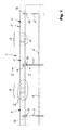
- FIG. 1 in FIG. 1 denotes a protective barrier strand, like it is especially rural, preferably wooded Environment, next to a lane 2 is arranged.
- the guardrail strand 1 essentially has one First spar 3 running parallel to roadway 2 round tree trunk sections 4 (see also FIGS. 2 to 4).
- the Firstholm 3 is on vertical posts 5 with a C-shaped cross section attached to the bottom 6 are rammed.
- the surfaces of the posts 5 are with provided with a coating that has a wood character.
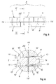
- each tree trunk section 4 from two trunk halves 7, 8.
- the parting plane TE of the stem halves 7, 8 runs vertically.
- FIGS. 1 and 5 it can be seen from FIGS. 1 and 5 that in the connection area 9 two tree trunk sections 4 the trunk halves 7, 8 arranged in the longitudinal direction offset from one another are.
- FIG. 6 reveals a total of twelve bolts 10 in pairs be provided with nuts 11 to the trunk halves 7, 8 of two abutting tree trunk sections 4 to connect securely.
- the bolts 10 penetrate holes 12 in the stem halves 7, 8 ( Figure 6), with their heads 13 in depressions 14 of Stem halves 8 lie.
- the nuts 11 are also in depressions 15 of the stem halves 7.
- a guardrail strand 1 in the embodiment of a guardrail strand 1 according to Figures 1 to 6 are the tree trunk sections 4 in steel shells 16 open to the top and stored with the shells 16 connected by wood screws 17 (figures 2 and 4). For this purpose, 16 corresponding holes are in the shells 18 provided. The shells 16 extend over the lower half of the circumference of the tree trunk sections 4.
- the dash-dotted lines in FIG. 2 also shown that the log sections 4 also fixed to the shells 16 by means of band clamps 28 could be.
- the band clamps 28 encompass the tree trunk sections 4 and the side areas of the shells 16.
- the wood screws 17 also serve to secure them.
- the shells are 16 with steel slip sleeves which are rectangular in cross section 19 welded to the top ends of the posts 5 overlap positively.
- the slip sleeves 19 are with the post 5 via two predetermined breaking screws arranged one above the other 20 connected ( Figures 2 and 4).
- Corresponding elongated holes 21 are provided in the slip sleeves 19.
- Tension element 22 in the form of an upright flat belt is incorporated.
- the tension element 22 is in particular made of a polyester fabric. It stretches throughout the entire length of the ridge spar 3. Es can in each case when installing the guardrail strand 1 a trunk half 7 or 8 of a log section 4 can be tacked on. Here it is from a supply roll unwindable.
- the tension element 22 is then with pierced and, as can be seen from Figures 5 and 6 is fixed between the stem halves 7, 8 incorporated.
- the width (height) of the tension element 22 corresponds the diameter of the ridge spar 3.
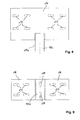
- a guardrail strand 1a of the figure 7 sees a ridge beam 3a and between the ridge beam 3a and the bottom 6 a further parallel central spar 23 before.
- the Firstholm 3a consists of vertically divided tree trunk sections 4a. These in turn consist of each two stem halves 7a, 8a together, in the vertical Abut cross planes QE of posts 5a.
- the upper ends of the posts 5a are made of slip sleeves 19a (see also FIG. 8), which can be seen in Vertical straps 24 extending in the longitudinal direction Wear elongated holes 25.
- the middle of the top ends of the Slip sleeves 19a welded tabs 24 are then in the parting plane TE of the stem halves 7a, 8a next to the through the first member 3a extending tension element 22. Die Connection is made using bolts 10 and nuts 11, as shown in Figure 6.
- the slip sleeve 19a according to FIG. 8 is also via a Breaking screw 20a with a C-shaped post 5a connected.
- the central spar 23 also consists of tree trunk sections 4b, which are composed of two stem halves 7b, 8b. Each log section 4b extends from post 5a to post 5a. The connection is made via extending in the parting plane TE of the center spar 23 Tabs 26 with elongated holes 27 ( Figure 9), the front welded to cross-sectional slip sleeves 19b are, which embrace the posts 5a and by means of two predetermined breaking screws 20b on the posts 5a are set.
- the center spar 23 can also between the Post 5a be provided with a tension element 22.
- the Slip sleeves 19b are provided with vertical elongated holes 28.
Landscapes
- Engineering & Computer Science (AREA)
- Life Sciences & Earth Sciences (AREA)
- Wood Science & Technology (AREA)
- Architecture (AREA)
- Civil Engineering (AREA)
- Structural Engineering (AREA)
- Refuge Islands, Traffic Blockers, Or Guard Fence (AREA)
- Protection Of Plants (AREA)
- Fencing (AREA)
- Road Paving Structures (AREA)
- Optical Fibers, Optical Fiber Cores, And Optical Fiber Bundles (AREA)
- Electronic Switches (AREA)
- Apparatus For Radiation Diagnosis (AREA)
Abstract
Description
Die Erfindung betrifft einen Schutzplankenstrang gemäß
den Merkmalen im Oberbegriff des Anspruchs 1.The invention relates to a guard rail strand according to
the features in the preamble of
Ein derartiger Schutzplankenstrang ist durch die DE 195 17 933 A1 bekannt. Hierbei wird der Firstholm aus halbierten Baumstammabschnitten von einem gespannten Stahlseil in Längsrichtung durchsetzt. Ein derartiger Schutzplankenstrang kann nicht nur hinsichtlich seines Materials und seiner Formgebung der ländlichen Umgebung einer Fahrbahn optisch ansprechend angepasst, sondern auch den Anforderungen gerecht werden, die an die Schutzfunktion reiner Stahl leitplanken gestellt werden.Such a guardrail strand is through the DE 195 17 933 A1 known. Here the Firstholm is out halved tree trunk sections from a tensioned Steel cable interspersed in the longitudinal direction. Such one Guardrail strand can not only with regard to its Materials and its shape of the rural environment adapted to a road surface in a visually appealing way, but also meet the requirements of the protective function pure steel guardrails.
Bei der bekannten Bauart eines Schutzplankenstrangs hat sich bei internen Anfahrversuchen herausgestellt, dass bei höheren Beanspruchungen das gespannte Drahtseil die Baumstammabschnitte durchschneiden kann. Der Firstholm kann sich dann nicht mehr ordnungsgemäß von den Pfosten lösen. Vielmehr zieht bei einem Aufprall durch ein schwereres Kraftfahrzeug der Firstholm die Pfosten mit weg von der Fahrbahn.Has in the known type of guard rail internal start-up attempts have shown that the tensioned wire rope at higher loads Can cut sections of tree trunk. The Firstholm can then no longer come off the post properly to solve. Rather, in the event of an impact, it pulls through a heavier one Motor vehicle the Firstholm with the posts off the roadway.
Der Erfindung liegt ausgehend vom Stand der Technik die
Aufgabe zugrunde, den im Oberbegriff des Anspruchs 1 beschriebenen
Schutzplankenstrang derart weiterzubilden,
dass er auch höheren Beanspruchungen durch schwere Kraftfahrzeuge
vollauf gerecht wird.The invention is based on the prior art
Task based on that described in the preamble of
Die Lösung dieser Aufgabe besteht nach der Erfindung in
den im kennzeichnenden Teil des Anspruchs 1 aufgeführten
Merkmalen.According to the invention, this object is achieved in
those listed in the characterizing part of
Danach wird das Zugelement nunmehr als Flachgurt aus einem textilen Material und/oder aus Kunststoff gestaltet und in hochkantiger Erstreckung zwischen die Stammhälften der den Firstholm bildenden Baumstammabschnitte eingegliedert. Insbesondere handelt es sich um ein Textil- und/oder Kunststoffgewebe, z.B. aus Polyestergarnen. Durch entsprechende Variation der Abmessungen des Zugelements in Verbindung mit der Materialwahl kann die Belastungsgrenze feinfühlig reguliert werden. Das Zugelement wird wie ein Sandwich behandelt und bei der Montage des Schutzplankenstrangs zwischen die Stammhälften gelegt. Hierbei kann das Zugelement von einer Rolle gewickelt und in beliebiger Länge zwischen die Stammhälften eingelegt werden. Hiermit ist der Vorteil verbunden, dass der Abstand der Pfosten nicht das bei Stahlschutzplanken genormte Rastermaß von 4.000 mm haben muss.Then the tension element is now made as a flat belt a textile material and / or made of plastic and in an upright extension between the stem halves of the log sections forming the Firstholm. In particular, it is a textile and / or plastic fabric, e.g. made of polyester yarn. By correspondingly varying the dimensions of the tension element in connection with the choice of material, the load limit be carefully regulated. The tension element is treated like a sandwich and when assembling the Guardrail strand placed between the trunk halves. Here, the tension element can be wound from a roll and inserted in any length between the stem halves become. This has the advantage that the distance the post not that of steel guardrails must have a standardized grid dimension of 4,000 mm.
Da der Firstholm über Schlupfhülsen und Sollbruchschrauben mit den Pfosten verbunden ist, wird er sich bei einem Fahrzeuganprall komplett von den Pfosten lösen und verbleibt auch bei von der Fahrbahn abgebogenen Pfosten in seiner ursprünglichen Höhe. Hier bildet dann das Zugelement ein wichtiges Sicherheitsglied zum Auffangen eines Kraftfahrzeugs. Dieses kann nicht über den Schutzplankenstrang hinweg fahren.Because the ridge spar over slip sleeves and predetermined breaking screws connected to the post, he will join one Release the vehicle impact completely from the posts and remain also in the case of posts bent off the road in its original height. The tension element then forms here an important safety element to catch a Motor vehicle. This cannot over the guardrail strand drive away.
Die Pfosten können aus Rohren bestehen oder einen C-förmigen Querschnitt aufweisen. Der Pfostenabstand in Längsrichtung des Schutzplankenstrangs richtet sich nach den jeweiligen Anforderungsstufen.The posts can consist of tubes or a C-shaped one Have cross-section. The post spacing in the longitudinal direction of the guardrail line depends on the respective requirement levels.
Um die Montage des Schutzplankenstrangs zu erleichtern,
sehen die Merkmale des Anspruchs 2 vor, dass das Zugelement
an mindestens eine Stammhälfte jedes Baumstammabschnitts
geheftet ist. Das Heften kann durch Annageln
oder mit Hilfe eines Tackers erfolgen.To facilitate the installation of the guardrail line,
provide the features of
Die den Firstholm bildenden Baumstammabschnitte sind gemäß
der Ausführungsform des Anspruchs 3 in nach oben offenen
und mit den Schlupfhülsen verbundenen, insbesondere
verschweißten, metallischen Schalen befestigt. Diese
Schalen haben etwa die Konturbreite der Pfosten und erstrecken
sich bevorzugt über etwa den unteren Umfangsbereich
der Baumstammabschnitte. Die Befestigung der Baumstammabschnitte
in den Schalen kann durch Schraubnägel
oder Holzschrauben erfolgen. Die metallischen Schlupfhülsen
übergreifen bei C-förmigen Pfosten diese Pfosten. Bei
runden Pfosten fassen die Schlupfhülsen bevorzugt in die
Pfosten. Schlupfhülsen und Laschen bestehen insbesondere
aus Stahl.The tree trunk sections forming the Firstholm are according to
the embodiment of
Gemäß Anspruch 4 werden die Baumstammabschnitte mittels
Bandschellen an den Schalen festgelegt. Hiermit kann
gezielt dem Charakter von Holz Rechnung getragen werden.According to
Eine weitere Ausführungsform der Erfindung besteht in den
Merkmalen des Anspruchs 5. Danach werden die Baumstammabschnitte
an metallischen Laschen festgelegt, insbesondere
mit diesen verschraubt, die ihrerseits mit den metallischen
Schlupfhülsen verbunden, insbesondere verschweißt,
sind. Diese Laschen erstrecken sich bevorzugt oberhalb
der Schlupfhülsen und liegen in der vertikalen Trennebene
zwischen den Stammhälften. Bei dieser Ausführungsform
sind die tragenden Metallteile bis auf die Pfosten von
den Stammhälften ummantelt.Another embodiment of the invention consists in the
Features of
Eine optisch ansprechende und stabile Verbindung der in
Längsrichtung aneinander stoßenden Baumstammabschnitte
wird mit den Merkmalen des Anspruchs 6 erzielt. Danach
sind die Stammhälften der aufeinanderfolgenden Baumstammabschnitte
in Längsrichtung zueinander versetzt. Auf
diese Art und Weise können zudem stabile Verbindungsbereiche
geschaffen werden.A visually appealing and stable connection of the in
Longitudinally abutting tree trunk sections
is achieved with the features of
Die Belastbarkeit eines Schutzplankenstrangs kann mit den
Merkmalen des Anspruchs 7 noch weiter erhöht werden. Dazu
ist in dem Höhenbereich zwischen dem Firstholm und dem
Boden ein zum Firstholm paralleler Mittenholm vorgesehen.
Auch dieser Mittenholm besteht aus Baumstammabschnitten,
die jeweils aus miteinander verschraubten Stammhälften
zusammengesetzt sind. Hierbei erstrecken sich die Baumstammabschnitte
bevorzugt von Pfosten zu Pfosten. Sie
sind an metallischen Laschen festgelegt, die in Längsrichtung
von metallischen Schlupfhülsen abstehen, die in
mittlerer Höhe mittels Sollbruchschrauben an den Pfosten
festgelegt sind. Auch der Mittenholm kann bei Bedarf von
einem Zugelement in Form eines Flachgurts aus textilem
Material und/oder aus Kunststoff in hochkantiger Erstreckung
durchzogen sein.The resilience of a guardrail strand can be with the
Features of
Bei einem Fahrzeuganprall wird sich der Firstholm komplett von den Pfosten lösen und dann wie ein Zugband wirken. Der Mittenholm wird sich etwas nach oben schieben und seine Aufhalteenergie ins Fahrzeug abgeben.In the event of a vehicle collision, the Firstholm becomes complete detach from the posts and then act like a drawstring. The center spar will push up a little and release its hold-up energy into the vehicle.
Die Erfindung ist nachfolgend anhand von in den Zeichnungen dargestellten Ausführungsbeispielen näher erläutert. Es zeigen:
Figur 1- in schematischer Seitenansicht einen Längenabschnitt eines Schutzplankenstrangs;
Figur 2- in vergrößertem Maßstab einen vertikalen
Querschnitt durch die Darstellung der
Figur 1 entlang der Linie II-II in zwei verschiedenen Ausführungsformen; Figur 3- eine Draufsicht auf die Darstellung der
Figur 2; Figur 4- eine Seitenansicht auf die Darstellung der
Figur 2; Figur 5- eine Draufsicht auf den Schutzplankenstrang
gemäß dem Ausschnitt V der
Figur 1 in vergrößertem Maßstab; Figur 6- einen vertikalen Querschnitt durch die Darstellung
der
Figur 5 entlang der Linie VI-VI in vergrößertem Maßstab und in 90° Versetzung; Figur 7- in schematischer Seitenansicht einen Längenabschnitt eines Schutzplankenstrangs gemäß einer weiteren Ausführungsform;
Figur 8- in vergrößerter Darstellung eine Schlupfhülse
mit Lasche zur Integration in den Firstholm
des Schutzplankenstrangs gemäß
Figur 7 und Figur 9- eine Schlupfhülse mit Laschen zur Integration
in den Mittenholm des Schutzplankenstrangs
gemäß
Figur 7.
- Figure 1
- a schematic side view of a longitudinal section of a guard rail strand;
- Figure 2
- on an enlarged scale a vertical cross section through the representation of Figure 1 along the line II-II in two different embodiments;
- Figure 3
- a plan view of the illustration of Figure 2;
- Figure 4
- a side view of the illustration of Figure 2;
- Figure 5
- a plan view of the guard rail strand according to section V of Figure 1 on an enlarged scale;
- Figure 6
- a vertical cross section through the representation of Figure 5 along the line VI-VI on an enlarged scale and in 90 ° offset;
- Figure 7
- a schematic side view of a longitudinal section of a guard rail strand according to a further embodiment;
- Figure 8
- in an enlarged view a slip sleeve with a tab for integration into the ridge spar of the guard rail strand according to FIGS. 7 and
- Figure 9
- a slip sleeve with tabs for integration into the central spar of the guard rail strand according to FIG. 7.
Mit 1 ist in der Figur 1 ein Schutzplankenstrang bezeichnet,
wie er in insbesondere ländlicher, bevorzugt waldiger
Umgebung, neben einer Fahrbahn 2 angeordnet ist.1 in FIG. 1 denotes a protective barrier strand,
like it is especially rural, preferably wooded
Environment, next to a
Der Schutzplankenstrang 1 weist einen im wesentlichen
parallel zu der Fahrbahn 2 verlaufenden Firstholm 3 aus
runden Baumstammabschnitten 4 auf (siehe auch Figuren 2
bis 4). Der Firstholm 3 ist an vertikalen Pfosten 5 mit
einem C-förmigen Querschnitt befestigt, die in den Boden
6 gerammt sind. Die Oberflächen der Pfosten 5 sind mit
einer Beschichtung versehen, die einen Holzcharakter aufweist.The
Wie die Figuren 2, 3, 5 und 6 erkennen lassen, besteht
jeder Baumstammabschnitt 4 aus zwei Stammhälften 7, 8.
Die Trennebene TE der Stammhälften 7, 8 verläuft vertikal.As can be seen in FIGS. 2, 3, 5 and 6, there is
each
Aus den Figuren 1 und 5 ist ersichtlich, dass im Verbindungsbereich
9 zweier Baumstammabschnitte 4 die Stammhälften
7, 8 in Längsrichtung zueinander versetzt angeordnet
sind. Auf diese Weise können, wie auch die Figur 6
erkennen lässt, insgesamt zwölf Schraubbolzen 10 paarweise
mit Muttern 11 vorgesehen werden, um die Stammhälften
7, 8 zweier aneinander stoßenden Baumstammabschnitte
4 sicher miteinander zu verbinden. Die Schraubbolzen 10
durchsetzen hierbei Bohrungen 12 in den Stammhälften 7, 8
(Figur 6), wobei ihre Köpfe 13 in Einsenkungen 14 der
Stammhälften 8 liegen. Auch die Muttern 11 liegen in Einsenkungen
15 der Stammhälften 7.It can be seen from FIGS. 1 and 5 that in the
Bei der Ausführungsform eines Schutzplankenstrangs 1 gemäß
den Figuren 1 bis 6 sind die Baumstammabschnitte 4 in
nach oben offenen stählernen Schalen 16 gelagert und mit
den Schalen 16 durch Holzschrauben 17 verbunden (Figuren
2 und 4). Dazu sind in den Schalen 16 entsprechende Bohrungen
18 vorgesehen. Die Schalen 16 erstrecken sich über
die untere Hälfte des Umfangs der Baumstammabschnitte 4.In the embodiment of a
In strichpunktierter Linienführung ist in der Figur 2
außerdem noch dargestellt, dass die Baumstammabschnitte 4
auch mittels Bandschellen 28 an den Schalen 16 festgelegt
sein können. Die Bandschellen 28 umfassen die Baumstammabschnitte
4 und die seitlichen Bereiche der Schalen
16. Die Holzschrauben 17 dienen auch zu ihrer Befestigung.The dash-dotted lines in FIG. 2
also shown that the
Wie die Figuren 1 bis 4 erkennen lassen, sind die Schalen
16 mit im Querschnitt rechteckigen stählernen Schlupfhülsen
19 verschweißt, welche die oberen Enden der Pfosten 5
formschlüssig übergreifen. Die Schlupfhülsen 19 sind mit
den Pfosten 5 über zwei übereinander angeordnete Sollbruchschrauben
20 verbunden (Figuren 2 und 4). Dazu sind
in den Schlupfhülsen 19 entsprechende Langlöcher 21 vorgesehen.As can be seen from FIGS. 1 to 4, the shells are
16 with steel slip sleeves which are rectangular in
Aus den Figuren 2, 3, 5 und 6 ist ersichtlich, dass zwischen
die Stammhälften 7, 8 der Baumstammabschnitte 4 ein
Zugelement 22 in Form eines hochkant gestellten Flachgurts
eingegliedert ist. Das Zugelement 22 besteht insbesondere
aus einem Polyestergewebe. Es erstreckt sich
durchgehend über die gesamte Länge des Firstholms 3. Es
kann bei der Montage des Schutzplankenstrangs 1 an jeweils
eine Stammhälfte 7 oder 8 eines Baumstammabschnitts
4 angetackert werden. Hierbei ist es von einer Vorratsrolle
abwickelbar. Bei der Verbindung der Stammhälften 7,
8 eines Baumstammabschnitts 4 wird das Zugelement 22 dann
mit durchbohrt und, wie aus den Figuren 5 und 6 ersichtlich
ist, dadurch fest zwischen die Stammhälften 7, 8
eingegliedert. Die Breite (Höhe) des Zugelements 22 entspricht
dem Durchmesser des Firstholms 3.It can be seen from FIGS. 2, 3, 5 and 6 that between
the trunk halves 7, 8 of the
Die Ausführungsform eines Schutzplankenstrangs 1a der Figur
7 sieht einen Firstholm 3a und zwischen dem Firstholm
3a und dem Boden 6 einen weiteren parallelen Mittenholm
23 vor.The embodiment of a guardrail strand 1a of the figure
7 sees a
Der Firstholm 3a besteht aus vertikal geteilten Baumstammabschnitten
4a. Diese setzen sich wiederum aus jeweils
zwei Stammhälften 7a, 8a zusammen, die in den vertikalen
Querebenen QE der Pfosten 5a aneinander stoßen.
Die oberen Enden der Pfosten 5a werden von Schlupfhülsen
19a übergriffen (siehe auch Figur 8), welche sich in
Längsrichtung erstreckende vertikale Laschen 24 mit
Langlöchern 25 tragen. Die mittig an die oberen Enden der
Schlupfhülsen 19a geschweißten Laschen 24 liegen dann in
der Trennebene TE der Stammhälften 7a, 8a neben dem sich
durch den Firstholm 3a erstreckenden Zugelement 22. Die
Verbindung erfolgt über Schraubbolzen 10 und Muttern 11,
wie in der Figur 6 dargestellt.The
Auch die Schlupfhülse 19a gemäß Figur 8 ist über eine
Sollbruchschraube 20a mit einem C-förmigen Pfosten 5a
verbunden.The
Der Mittenholm 23 besteht ebenfalls aus Baumstammabschnitten
4b, die sich aus zwei Stammhälften 7b, 8b zusammensetzen.
Jeder Baumstammabschnitt 4b erstreckt sich
von Pfosten 5a zu Pfosten 5a. Die Verbindung erfolgt über
sich in der Trennebene TE des Mittenholms 23 erstreckende
Laschen 26 mit Langlöchern 27 (Figur 9), die stirnseitig
an im Querschnitt rechteckige Schlupfhülsen 19b angeschweißt
sind, welche die Pfosten 5a umgreifen und mittels
zweier Sollbruchschrauben 20b an den Pfosten 5a
festgelegt sind. Auch der Mittenholm 23 kann zwischen den
Pfosten 5a mit einem Zugelement 22 versehen sein. Die
Schlupfhülsen 19b sind mit vertikalen Langlöchern 28 versehen. The
Claims (7)
Applications Claiming Priority (2)
| Application Number | Priority Date | Filing Date | Title |
|---|---|---|---|
| DE19757092A DE19757092C2 (en) | 1997-12-20 | 1997-12-20 | A protective barrier |
| DE19757092 | 1997-12-20 |
Publications (3)
| Publication Number | Publication Date |
|---|---|
| EP0924346A2 true EP0924346A2 (en) | 1999-06-23 |
| EP0924346A3 EP0924346A3 (en) | 2001-09-12 |
| EP0924346B1 EP0924346B1 (en) | 2004-05-06 |
Family
ID=7852887
Family Applications (1)
| Application Number | Title | Priority Date | Filing Date |
|---|---|---|---|
| EP98123111A Expired - Lifetime EP0924346B1 (en) | 1997-12-20 | 1998-12-03 | Guard rail |
Country Status (3)
| Country | Link |
|---|---|
| EP (1) | EP0924346B1 (en) |
| AT (1) | ATE266126T1 (en) |
| DE (2) | DE19757092C2 (en) |
Cited By (2)
| Publication number | Priority date | Publication date | Assignee | Title |
|---|---|---|---|---|
| FR2796662A1 (en) * | 1999-07-22 | 2001-01-26 | Maussion Jacques De | Motor road safety barrier has at least one timber rail reinforced by synthetic fibres |
| FR2815976A1 (en) * | 2000-10-30 | 2002-05-03 | Maussion Jacques De | Crash barrier has wooden rails whose ends are fastened to mounting plate attached to support posts by bolts which pass through elastomeric sleeves inserted in bores in rail |
Families Citing this family (3)
| Publication number | Priority date | Publication date | Assignee | Title |
|---|---|---|---|---|
| EP1486614A1 (en) | 2003-06-12 | 2004-12-15 | SPIG Schutzplanken-Produktions-Gesellschaft mbH & Co.KG | Guard rail |
| DE10326414B3 (en) | 2003-06-12 | 2004-08-26 | Spig Schutzplanken-Produktions-Gesellschaft Mbh & Co Kg | Roadside protective barrier, to line the sides of traffic lanes, has round wood horizontal beam sections butted together with a longitudinal metal reinforcement girder through them, mounted to vertical posts |
| DE102015108873B4 (en) | 2015-06-04 | 2018-07-19 | Jürgen Hinrichsen | Restraint system on traffic routes |
Citations (1)
| Publication number | Priority date | Publication date | Assignee | Title |
|---|---|---|---|---|
| DE19517933A1 (en) | 1995-05-18 | 1996-11-21 | Spig Schutzplanken Prod Gmbh | Guardrail strand |
Family Cites Families (6)
| Publication number | Priority date | Publication date | Assignee | Title |
|---|---|---|---|---|
| FR1531420A (en) * | 1967-03-07 | 1968-07-05 | Eurotechni Office | Guardrail for roads and highways |
| CH449689A (en) * | 1967-05-19 | 1968-01-15 | Alusuisse | Road barrier made of composite material |
| DE1952920A1 (en) * | 1968-10-22 | 1970-05-06 | Werner Zahlmann | Process for the production of panels, boards or the like. based on wood |
| FR2589176B1 (en) * | 1985-10-28 | 1987-12-18 | Gaillard Rondino Cie Fse Ets | DEVICE FOR CONSTRUCTING AND ASSEMBLING WOOD SECURITY SLIDES OR BARRIERS |
| FR2703706B1 (en) * | 1993-04-07 | 1995-06-23 | Cihb | WOOD-METAL ROAD SAFETY SLIDE OR BARRIER. |
| FR2718473B1 (en) * | 1994-04-07 | 1996-07-19 | France Bois Impregnes Sa | Safety barrier for curbs on taxiways. |
-
1997
- 1997-12-20 DE DE19757092A patent/DE19757092C2/en not_active Expired - Fee Related
-
1998
- 1998-12-03 DE DE59811326T patent/DE59811326D1/en not_active Expired - Lifetime
- 1998-12-03 AT AT98123111T patent/ATE266126T1/en not_active IP Right Cessation
- 1998-12-03 EP EP98123111A patent/EP0924346B1/en not_active Expired - Lifetime
Patent Citations (1)
| Publication number | Priority date | Publication date | Assignee | Title |
|---|---|---|---|---|
| DE19517933A1 (en) | 1995-05-18 | 1996-11-21 | Spig Schutzplanken Prod Gmbh | Guardrail strand |
Cited By (4)
| Publication number | Priority date | Publication date | Assignee | Title |
|---|---|---|---|---|
| FR2796662A1 (en) * | 1999-07-22 | 2001-01-26 | Maussion Jacques De | Motor road safety barrier has at least one timber rail reinforced by synthetic fibres |
| WO2001007718A1 (en) * | 1999-07-22 | 2001-02-01 | Jacques De Maussion | Crash barrier for highway or the like comprising wooden fibre-reinforced rails |
| US6733002B1 (en) | 1999-07-22 | 2004-05-11 | De Maussion Jacques | Crash barrier for highway or the like comprising wooden fiber-reinforced rails |
| FR2815976A1 (en) * | 2000-10-30 | 2002-05-03 | Maussion Jacques De | Crash barrier has wooden rails whose ends are fastened to mounting plate attached to support posts by bolts which pass through elastomeric sleeves inserted in bores in rail |
Also Published As
| Publication number | Publication date |
|---|---|
| DE19757092C2 (en) | 2002-12-05 |
| ATE266126T1 (en) | 2004-05-15 |
| EP0924346A3 (en) | 2001-09-12 |
| EP0924346B1 (en) | 2004-05-06 |
| DE59811326D1 (en) | 2004-06-09 |
| DE19757092A1 (en) | 1999-07-01 |
Similar Documents
| Publication | Publication Date | Title |
|---|---|---|
| EP1926859B1 (en) | Crash barrier run | |
| EP1762660A1 (en) | Device for traffic guiding | |
| AT390979B (en) | ARRANGEMENT ARRANGEMENT | |
| DE3530260A1 (en) | FENCE | |
| DE4224998C1 (en) | Protective crash barrier for highways - comprises posts anchored in ground, deformation profile on road side, upper and lower longitudinal rails | |
| EP0462307A1 (en) | Section of a guard | |
| EP1630295B1 (en) | Passive protection means beside a lane of a motor vehicle road | |
| DE3820930A1 (en) | TRAIL SEPARATION DEVICE | |
| CH636663A5 (en) | Road barrier device for keeping vehicles on a road | |
| EP0743398B1 (en) | Guard rail | |
| EP0924346B1 (en) | Guard rail | |
| DE102008017939B3 (en) | Vehicle restraint system for motor vehicle, has flanges resting against inner sides of flat bracket of protective planks, and longitudinal channels locked with poles above base when reinforcing profile overlaps in area between poles | |
| EP1816263A1 (en) | Device for traffic guiding | |
| DE202007019215U1 (en) | Vehicle restraint system on traffic routes | |
| DE19536915C2 (en) | Guardrail arrangement | |
| DE1534540B1 (en) | Guardrail for roads, especially in simple design | |
| DE19735507C1 (en) | Roadway protective crash-barrier for vehicles | |
| EP1486615B1 (en) | A safety barrier assembly | |
| DE9405557U1 (en) | Guardrail or road safety barrier | |
| EP0761889B1 (en) | Guardrail arrangement | |
| DE1534538A1 (en) | Security fence | |
| EP1486614A1 (en) | Guard rail | |
| DE9006930U1 (en) | Guardrail | |
| DE1963458A1 (en) | Guiding device for delimiting roadways | |
| DE19822715B4 (en) | guide |
Legal Events
| Date | Code | Title | Description |
|---|---|---|---|
| PUAI | Public reference made under article 153(3) epc to a published international application that has entered the european phase |
Free format text: ORIGINAL CODE: 0009012 |
|
| AK | Designated contracting states |
Kind code of ref document: A2 Designated state(s): AT BE CH CY DE DK ES FI FR GB GR IE IT LI LU MC NL PT SE Kind code of ref document: A2 Designated state(s): AT CH DE FR IT LI SE |
|
| AX | Request for extension of the european patent |
Free format text: AL;LT;LV;MK;RO;SI |
|
| PUAL | Search report despatched |
Free format text: ORIGINAL CODE: 0009013 |
|
| AK | Designated contracting states |
Kind code of ref document: A3 Designated state(s): AT BE CH CY DE DK ES FI FR GB GR IE IT LI LU MC NL PT SE |
|
| AX | Request for extension of the european patent |
Free format text: AL;LT;LV;MK;RO;SI |
|
| RIC1 | Information provided on ipc code assigned before grant |
Free format text: 7E 01F 15/04 A, 7B 29C 70/08 B, 7B 32B 21/10 B, 7B 27D 1/04 B |
|
| 17P | Request for examination filed |
Effective date: 20010731 |
|
| AKX | Designation fees paid |
Free format text: AT CH DE FR IT LI SE |
|
| GRAP | Despatch of communication of intention to grant a patent |
Free format text: ORIGINAL CODE: EPIDOSNIGR1 |
|
| GRAP | Despatch of communication of intention to grant a patent |
Free format text: ORIGINAL CODE: EPIDOSNIGR1 |
|
| GRAS | Grant fee paid |
Free format text: ORIGINAL CODE: EPIDOSNIGR3 |
|
| GRAA | (expected) grant |
Free format text: ORIGINAL CODE: 0009210 |
|
| AK | Designated contracting states |
Kind code of ref document: B1 Designated state(s): AT CH DE FR IT LI SE |
|
| PG25 | Lapsed in a contracting state [announced via postgrant information from national office to epo] |
Ref country code: IT Free format text: LAPSE BECAUSE OF FAILURE TO SUBMIT A TRANSLATION OF THE DESCRIPTION OR TO PAY THE FEE WITHIN THE PRESCRIBED TIME-LIMIT;WARNING: LAPSES OF ITALIAN PATENTS WITH EFFECTIVE DATE BEFORE 2007 MAY HAVE OCCURRED AT ANY TIME BEFORE 2007. THE CORRECT EFFECTIVE DATE MAY BE DIFFERENT FROM THE ONE RECORDED. Effective date: 20040506 |
|
| REG | Reference to a national code |
Ref country code: CH Ref legal event code: EP |
|
| REF | Corresponds to: |
Ref document number: 59811326 Country of ref document: DE Date of ref document: 20040609 Kind code of ref document: P |
|
| PG25 | Lapsed in a contracting state [announced via postgrant information from national office to epo] |
Ref country code: SE Free format text: LAPSE BECAUSE OF FAILURE TO SUBMIT A TRANSLATION OF THE DESCRIPTION OR TO PAY THE FEE WITHIN THE PRESCRIBED TIME-LIMIT Effective date: 20040806 |
|
| PG25 | Lapsed in a contracting state [announced via postgrant information from national office to epo] |
Ref country code: AT Free format text: LAPSE BECAUSE OF NON-PAYMENT OF DUE FEES Effective date: 20041203 |
|
| PG25 | Lapsed in a contracting state [announced via postgrant information from national office to epo] |
Ref country code: LI Free format text: LAPSE BECAUSE OF NON-PAYMENT OF DUE FEES Effective date: 20041231 Ref country code: CH Free format text: LAPSE BECAUSE OF NON-PAYMENT OF DUE FEES Effective date: 20041231 |
|
| ET | Fr: translation filed | ||
| PLBE | No opposition filed within time limit |
Free format text: ORIGINAL CODE: 0009261 |
|
| STAA | Information on the status of an ep patent application or granted ep patent |
Free format text: STATUS: NO OPPOSITION FILED WITHIN TIME LIMIT |
|
| 26N | No opposition filed |
Effective date: 20050208 |
|
| REG | Reference to a national code |
Ref country code: CH Ref legal event code: PL |
|
| PGFP | Annual fee paid to national office [announced via postgrant information from national office to epo] |
Ref country code: DE Payment date: 20100923 Year of fee payment: 13 |
|
| PGFP | Annual fee paid to national office [announced via postgrant information from national office to epo] |
Ref country code: FR Payment date: 20120105 Year of fee payment: 14 |
|
| REG | Reference to a national code |
Ref country code: FR Ref legal event code: ST Effective date: 20130830 |
|
| REG | Reference to a national code |
Ref country code: DE Ref legal event code: R119 Ref document number: 59811326 Country of ref document: DE Effective date: 20130702 |
|
| PG25 | Lapsed in a contracting state [announced via postgrant information from national office to epo] |
Ref country code: DE Free format text: LAPSE BECAUSE OF NON-PAYMENT OF DUE FEES Effective date: 20130702 |
|
| PG25 | Lapsed in a contracting state [announced via postgrant information from national office to epo] |
Ref country code: FR Free format text: LAPSE BECAUSE OF NON-PAYMENT OF DUE FEES Effective date: 20130102 |