EP0924155B2 - Hydraulic elevator without a machineroom - Google Patents
Hydraulic elevator without a machineroom Download PDFInfo
- Publication number
- EP0924155B2 EP0924155B2 EP98309942A EP98309942A EP0924155B2 EP 0924155 B2 EP0924155 B2 EP 0924155B2 EP 98309942 A EP98309942 A EP 98309942A EP 98309942 A EP98309942 A EP 98309942A EP 0924155 B2 EP0924155 B2 EP 0924155B2
- Authority
- EP
- European Patent Office
- Prior art keywords
- tank
- car
- pump
- cylinder
- hoistway
- Prior art date
- Legal status (The legal status is an assumption and is not a legal conclusion. Google has not performed a legal analysis and makes no representation as to the accuracy of the status listed.)
- Expired - Lifetime
Links
- 239000012530 fluid Substances 0.000 claims description 23
- 230000007246 mechanism Effects 0.000 claims description 8
- 230000002452 interceptive effect Effects 0.000 claims 1
- 230000008901 benefit Effects 0.000 description 4
- 238000004891 communication Methods 0.000 description 1
- 238000009434 installation Methods 0.000 description 1
- 238000012423 maintenance Methods 0.000 description 1
Images
Classifications
-
- B—PERFORMING OPERATIONS; TRANSPORTING
- B66—HOISTING; LIFTING; HAULING
- B66B—ELEVATORS; ESCALATORS OR MOVING WALKWAYS
- B66B9/00—Kinds or types of lifts in, or associated with, buildings or other structures
- B66B9/04—Kinds or types of lifts in, or associated with, buildings or other structures actuated pneumatically or hydraulically
Definitions
- the present invention relates to hydraulic elevators.
- Conventional hydraulic elevators include a hydraulically driven ram to raise an elevator car. Lowering of the car is typically accomplished by permitting fluid to exit the cylinder of the hydraulic ram and using the weight of the car to force the fluid out of the cylinder.
- the piston may be directly engaged with the car or may be engaged with the car via a rope fixed to the hoistway and engaged with a sheave on a yoke on the piston. The latter arrangement provides the benefit of not requiring a hole under the hoistway to receive the hydraulic cylinder.
- hydraulic elevators as compared to traction elevators is the lower cost of the installation.
- Another traditional advantage is that the machineroom for the hydraulic elevator may be located anywhere in the building, rather than above the hoistway as in traditional traction elevators. Even though the machineroom for a hydraulic elevator may be remotely located, it is still necessary to provide such a space in order to provide a closed and protected area for the hydraulic components: the fluid tank, the pump (typically submerged in the tank of fluid), and the valves associated with the pump and tank.
- the machineroom includes a controller that includes the various electrical components for the hydraulic elevator system.
- An elevator system having the feature, as set forth in the preamble of claim 1 is known from SE-B-332698.
- a elevator system having a car movable within a hoistway, the system including a hydraulic cylinder, a fluid tank, a pump for moving fluid between the tank and cylinder, and a valve block that controls the flow of fluid between the tank and cylinder, the pump and the value block operating to transfer fluid to or from the cylinder to raise or lower the car during operation of the hydraulic elevator system wherein the valve block is located remotely from the tank and the pump.
- the pump and tank may be located in the hoistway and the valve block may be located in a cabinet along with various electronic components of the hydraulic elevator system.
- the cabinet may be conveniently positioned adjacent to a landing so that a mechanic will have access to the valve block and electronic control without having to enter the hoistway.
- the hydraulic elevator system includes a car and a hydraulic cylinder positioned adjacent to the travel path of the car and mounted on a support, and wherein the pump and tank are positioned underneath the support.
- This arrangement of the cylinder, pump and tank provides a compact configuration that minimizes the space requirements of the hoistway.
- the cylinder includes a sheave engaged with a rope, wherein the rope is attached to the car by a rope hitch, and wherein the rope hitch is disposed on the car in a position to avoid interference when the car is adjacent to the tank and pump.
- This particular embodiment provides a configuration that permits the use of a roped hydraulic elevator without a machineroom.
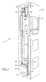
- a hydraulic elevator system 12 which includes a car 14 engaged with a pair of guide rails 16, a hydraulic cylinder 18 having a piston 20, a fluid tank 22 having a pump 24 disposed within the tank 22, and a plurality of ropes 26.
- the ropes 26 have one end attached to the car 14 by a rope hitch 28 and the opposite end anchored in the hoistway 29.
- the ropes 26 extend over a sheave 30 mounted on the upper end of the piston 20. Movement of the piston 20 is guided by a yoke 32 engaged with the pair of guide rails 16.
- the piston 20 moves within the cylinder 18 and causes the sheave 30 to raise and lower within the hoistway 29. Movement of the sheave 30 causes the car 14 to raise and lower in the hoistway 29 via the engagement with the ropes 26.
- the cylinder 18 includes a cylinder stand 34 that is mounted on a support assembly 36 positioned between the guide rails 16.
- the support assembly 36 includes a horizontal support 38, formed from a conventional I-beam structure, and a pair of vertical uprights 40 that are adjacent to the pair of guide rails 16 and are supported by the bottom or pit 42 of the hoistway 29.
- the horizontal support 38 also provides an anchor point 44 for the ropes 26.
- the cylinder 18 is raised above or off-set from the pit 42.
- the integral tank 22 and pump 24 are disposed in the opening defined by the support assembly 36.
- the pump 24 is internal to the tank 22 and submerged in the fluid. As a result of not integrating a valve block and various other valve components to the tank 22 and pump 24, the size of the tank 22 is minimized and may be proportioned to fit in the available space.
- the cylinder 18, support assembly 36, guide rails 16, tank 22 and pump 24 are all positioned along one side of the travel path of the car 14.
- the car 14 may be adjacent to one or more of the components in the hoistway 29.
- the rope hitch 28 is positioned at the top of the car 14.
- the ropes are hitched or engaged with the bottom of the car to maximize the rise of the car.
- the off-set produced by the support assembly 36 increases the rise of the car 14 and therefore the ropes 26 may be engaged or hitched to the top of the car 14 without significantly affecting the rise of the car 14.
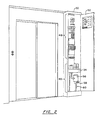
- control valve assembly 46 The flow of fluid between the tank 22 and cylinder 18 is controlled by a control valve assembly 46 and an electronic controller 48.
- These devices 46,48 as shown in Fig. 2, are located in a cabinet 50 positioned adjacent to one of the landings of the hoistway 29. Access to the control valve assembly 46 and controller 48 is through a locked door 52. The door 52 is locked to prevent unauthorized access to the controller 48 and the control valve assembly 46.
- the electronic controller 48 is in the upper part of the cabinet 50 and the control valve assembly 46 in is the lower part of the cabinet. This particular arrangement takes advantage of the height of the cabinet 50, and the possibility to separate the electronic controller 48 into components that may be mounted in the cabinet 50 or on the door 52, in order to minimize the space requirements of the cabinet 50.
- the cabinet 50 may be located in other convenient locations.
- the cabinet 50 may be separated into two or more cabinets. I n this configuration, the electronic controller 48 may be separated from the control valve assembly 46, if desired. Further, the controller and control valve assembly, including the valve block, may be separated into multiple modules, with each module conveniently located.
- the control valve assembly 46 includes a valve block 54, a muffler 56 and a manually operable release mechanism 58.
- the control valve assembly 46 is in fluid communication with the tank 22 by a plurality of fluid lines 60.
- the valve block 54 includes various valve stems and channels that control the flow of fluid between the cylinder 18 and pump 24 using conventional valve technology.
- the muffler 56 regulates the fluid flow from the valve block 54 to the cylinder 18.
- the release mechanism 58 permits a mechanic to manually open the valves to flow fluid from the cylinder 18 and into the tank 22.
- the manual operation of the valves may be used during emergency operations to lower the car 14 and evacuate passengers.
- a manually operable mechanism 58 other mechanisms may be used, such as electrically controllable actuators connected to a back-up power supply.
- the electronic controller 48 signals the pump 24 and valve block 54 to operate in the desired manner to transfer fluid to or from the cylinder 18 and to raise or lower the car 14. If service of the hydraulic elevator system 12 is required, a mechanic may get access to both the controller 48 and the valve block 54 by unlocking the cabinet 50. Locating the cabinet 50 with the controller 48 and valve block 54 near a landing facilitates the maintenance of the hydraulic elevator system 12. In addition, in the event of an emergency, the mechanic may get access to the manual release mechanism 58 through the cabinet 50.
Landscapes
- Engineering & Computer Science (AREA)
- Automation & Control Theory (AREA)
- Structural Engineering (AREA)
- Types And Forms Of Lifts (AREA)
- Fluid-Pressure Circuits (AREA)
Applications Claiming Priority (2)
| Application Number | Priority Date | Filing Date | Title |
|---|---|---|---|
| US08/995,507 US6378660B1 (en) | 1997-12-22 | 1997-12-22 | Hydraulic elevator without a machineroom |
| US995507 | 1997-12-22 |
Publications (4)
| Publication Number | Publication Date |
|---|---|
| EP0924155A2 EP0924155A2 (en) | 1999-06-23 |
| EP0924155A3 EP0924155A3 (en) | 1999-11-10 |
| EP0924155B1 EP0924155B1 (en) | 2002-05-02 |
| EP0924155B2 true EP0924155B2 (en) | 2005-06-22 |
Family
ID=25541906
Family Applications (1)
| Application Number | Title | Priority Date | Filing Date |
|---|---|---|---|
| EP98309942A Expired - Lifetime EP0924155B2 (en) | 1997-12-22 | 1998-12-04 | Hydraulic elevator without a machineroom |
Country Status (4)
| Country | Link |
|---|---|
| US (1) | US6378660B1 (es) |
| EP (1) | EP0924155B2 (es) |
| DE (1) | DE69805147T3 (es) |
| ES (1) | ES2173553T5 (es) |
Families Citing this family (17)
| Publication number | Priority date | Publication date | Assignee | Title |
|---|---|---|---|---|
| IT1306053B1 (it) * | 1998-06-09 | 2001-05-29 | Menozzi Renzo S R L | Ascensore idraulico |
| US6371005B1 (en) * | 1999-08-30 | 2002-04-16 | Otis Elevator Company | Hydraulic power unit for an elevator drive |
| US6719099B2 (en) | 2002-05-13 | 2004-04-13 | Inventio Ag | Integral elevator hydraulic power unit |
| BR0316297B1 (pt) * | 2002-11-18 | 2012-09-04 | unidade para monitoração de elevador e procedimento para a manutenção de uma unidade de monitoração de elevador. | |
| ITRM20030007A1 (it) * | 2003-01-10 | 2004-07-11 | Otis Elevator Co | Dispositivo di sollevamento a pistone, in particolare |
| FR2877932B1 (fr) * | 2003-08-26 | 2007-02-16 | Thyssenkrupp Elevator Mfg F | Systeme d'ascenseur pourvu d'une unite de motorisation sur contrepoids |
| US7946391B2 (en) | 2005-07-19 | 2011-05-24 | Bucher Hydraulics Ag | Hydraulic elevator without machine room |
| EP2376359B1 (en) * | 2008-12-19 | 2015-01-21 | Otis Elevator Company | Elevator door frame with electronics housing |
| US9517921B2 (en) | 2011-05-20 | 2016-12-13 | Otis Elevator Company | Machine roomless hydraulic elevator system |
| EP2530043A1 (de) * | 2011-05-30 | 2012-12-05 | Inventio AG | Aufzugschachtabschluss mit einer Aufzugkontrollanordnung |
| EP2530044A1 (de) * | 2011-05-30 | 2012-12-05 | Inventio AG | Aufzugschachtabschluss mit einer Aufzugkontrollanordnung |
| JP5952537B2 (ja) * | 2011-07-21 | 2016-07-13 | パナソニック ホームエレベーター株式会社 | エレベータ昇降装置 |
| JP5952538B2 (ja) * | 2011-07-21 | 2016-07-13 | パナソニック ホームエレベーター株式会社 | エレベータ昇降装置 |
| CN104703902B (zh) * | 2012-10-03 | 2016-08-17 | 三菱电机株式会社 | 电梯控制盘和使用电梯控制盘的电梯装置 |
| US9573791B2 (en) * | 2013-02-13 | 2017-02-21 | Kone Corporation | Elevators and elevator arrangements with maintenance cabinet in landing wall |
| US10647546B2 (en) * | 2016-12-16 | 2020-05-12 | Otis Elevator Company | Hydraulically activated shutoff valve for a hydraulic elevator system |
| RU2650285C1 (ru) * | 2017-02-07 | 2018-04-11 | Публичное акционерное общество "Невское проектно-конструкторское бюро" | Гидравлический привод корабельного подъемника |
Family Cites Families (9)
| Publication number | Priority date | Publication date | Assignee | Title |
|---|---|---|---|---|
| SE332698B (es) | 1968-05-30 | 1971-02-15 | Asea Ab | |
| US4438831A (en) * | 1980-01-07 | 1984-03-27 | Westinghouse Electric Corp. | Elevator system |
| JPS63106289A (ja) * | 1986-10-22 | 1988-05-11 | 株式会社日立製作所 | 流体圧エレベ−タ |
| FI83204C (fi) * | 1987-11-04 | 1991-06-10 | Kone Oy | Foerfarande och anordning foer foerbaettring av verkningsgraden hos en motorstyrd hydraulhiss. |
| JPH02296497A (ja) | 1989-05-11 | 1990-12-07 | Shoji Uchikawa | 3指向特性を有するマイクロホン |
| JPH04169491A (ja) * | 1990-10-31 | 1992-06-17 | Taiyo Ltd | 油圧式エレベータ装置 |
| JPH07114228A (ja) | 1993-10-15 | 1995-05-02 | Canon Aptecs Kk | 原稿搬送装置及び投影装置 |
| FI95456C (fi) | 1994-05-04 | 1996-02-12 | Kone Oy | Järjestely hissikuilun seinän aukossa ja kojetaulu |
| JPH08310770A (ja) * | 1995-05-12 | 1996-11-26 | Hitachi Ltd | 油圧式エレベータ |
-
1997
- 1997-12-22 US US08/995,507 patent/US6378660B1/en not_active Expired - Lifetime
-
1998
- 1998-12-04 ES ES98309942T patent/ES2173553T5/es not_active Expired - Lifetime
- 1998-12-04 EP EP98309942A patent/EP0924155B2/en not_active Expired - Lifetime
- 1998-12-04 DE DE69805147T patent/DE69805147T3/de not_active Expired - Lifetime
Also Published As
| Publication number | Publication date |
|---|---|
| ES2173553T5 (es) | 2005-10-16 |
| EP0924155A3 (en) | 1999-11-10 |
| DE69805147D1 (de) | 2002-06-06 |
| ES2173553T3 (es) | 2002-10-16 |
| US6378660B1 (en) | 2002-04-30 |
| DE69805147T2 (de) | 2003-03-06 |
| DE69805147T3 (de) | 2005-12-08 |
| EP0924155A2 (en) | 1999-06-23 |
| EP0924155B1 (en) | 2002-05-02 |
Similar Documents
| Publication | Publication Date | Title |
|---|---|---|
| EP0924155B2 (en) | Hydraulic elevator without a machineroom | |
| EP0415218B1 (en) | Placement of a drive unit for an elevator | |
| US9505585B2 (en) | Method for modernizing a hydraulic elevator | |
| KR101225035B1 (ko) | 엘리베이터 기계 지지체에 지지된 제어 전자기기를 포함한 엘리베이터 시스템 | |
| EP2361215B1 (en) | Elevator system and installation method | |
| US20100012436A1 (en) | Hydraulic elevator system | |
| US4529062A (en) | Elevator system | |
| SG181744A1 (en) | Double-decker lift installation | |
| JP5193561B2 (ja) | 油圧シリンダを使用した昇降装置及び該昇降装置における緊急制御方法 | |
| CA2287787C (en) | Elevator with machine room below | |
| US6085872A (en) | Roped hydraulic elevator | |
| WO2003013996A1 (en) | Hydraulic lift with the machine room incorporated into the hoist way | |
| JP2000053343A (ja) | エレベータ装置 | |
| GB2383791A (en) | Modernisation of hydraulic elevators | |
| MXPA97007934A (es) | Elevador hidraulico que tiene un contrapeso | |
| ITMI20010728A1 (it) | Azionamento oleodinamico per ascensori e montacarichi con centralina bel vano corsa | |
| EP0924156B1 (en) | Elevator with onboard driving means | |
| US4466510A (en) | Automatic floor-leveling means for a cable-suspended elevator | |
| US6158554A (en) | Safety device for moving the lift cabin in case of fault of the main lifting system | |
| CA1176185A (en) | Hydraulic elevators | |
| US20250353704A1 (en) | Method of providing access to at least one component of an elevator system and elevator system | |
| GB2411887A (en) | Lift retrofitting set | |
| JP2004001969A (ja) | 油圧エレベータ | |
| GB2209324A (en) | Improved hydraulic lift construction | |
| EP1857398A9 (en) | Elevator installation comprising an auxiliary system for moving the passenger car |
Legal Events
| Date | Code | Title | Description |
|---|---|---|---|
| PUAI | Public reference made under article 153(3) epc to a published international application that has entered the european phase |
Free format text: ORIGINAL CODE: 0009012 |
|
| AK | Designated contracting states |
Kind code of ref document: A2 Designated state(s): DE ES FR IT |
|
| AX | Request for extension of the european patent |
Free format text: AL;LT;LV;MK;RO;SI |
|
| PUAL | Search report despatched |
Free format text: ORIGINAL CODE: 0009013 |
|
| AK | Designated contracting states |
Kind code of ref document: A3 Designated state(s): AT BE CH CY DE DK ES FI FR GB GR IE IT LI LU MC NL PT SE |
|
| AX | Request for extension of the european patent |
Free format text: AL;LT;LV;MK;RO;SI |
|
| RIC1 | Information provided on ipc code assigned before grant |
Free format text: 6B 66B 9/04 A, 6B 66B 11/00 B |
|
| 17P | Request for examination filed |
Effective date: 19991203 |
|
| AKX | Designation fees paid |
Free format text: DE ES FR IT |
|
| GRAG | Despatch of communication of intention to grant |
Free format text: ORIGINAL CODE: EPIDOS AGRA |
|
| 17Q | First examination report despatched |
Effective date: 20010807 |
|
| GRAG | Despatch of communication of intention to grant |
Free format text: ORIGINAL CODE: EPIDOS AGRA |
|
| GRAH | Despatch of communication of intention to grant a patent |
Free format text: ORIGINAL CODE: EPIDOS IGRA |
|
| GRAH | Despatch of communication of intention to grant a patent |
Free format text: ORIGINAL CODE: EPIDOS IGRA |
|
| GRAA | (expected) grant |
Free format text: ORIGINAL CODE: 0009210 |
|
| AK | Designated contracting states |
Kind code of ref document: B1 Designated state(s): DE ES FR IT |
|
| REF | Corresponds to: |
Ref document number: 69805147 Country of ref document: DE Date of ref document: 20020606 |
|
| ET | Fr: translation filed | ||
| ET | Fr: translation filed | ||
| REG | Reference to a national code |
Ref country code: ES Ref legal event code: FG2A Ref document number: 2173553 Country of ref document: ES Kind code of ref document: T3 |
|
| PLBQ | Unpublished change to opponent data |
Free format text: ORIGINAL CODE: EPIDOS OPPO |
|
| PLBI | Opposition filed |
Free format text: ORIGINAL CODE: 0009260 |
|
| PLBF | Reply of patent proprietor to notice(s) of opposition |
Free format text: ORIGINAL CODE: EPIDOS OBSO |
|
| 26 | Opposition filed |
Opponent name: LEISTRITZ HYDRAULIK GMBH Effective date: 20030203 |
|
| PLAX | Notice of opposition and request to file observation + time limit sent |
Free format text: ORIGINAL CODE: EPIDOSNOBS2 |
|
| PLAX | Notice of opposition and request to file observation + time limit sent |
Free format text: ORIGINAL CODE: EPIDOSNOBS2 |
|
| PLBB | Reply of patent proprietor to notice(s) of opposition received |
Free format text: ORIGINAL CODE: EPIDOSNOBS3 |
|
| PLAY | Examination report in opposition despatched + time limit |
Free format text: ORIGINAL CODE: EPIDOSNORE2 |
|
| PLBC | Reply to examination report in opposition received |
Free format text: ORIGINAL CODE: EPIDOSNORE3 |
|
| PUAH | Patent maintained in amended form |
Free format text: ORIGINAL CODE: 0009272 |
|
| STAA | Information on the status of an ep patent application or granted ep patent |
Free format text: STATUS: PATENT MAINTAINED AS AMENDED |
|
| 27A | Patent maintained in amended form |
Effective date: 20050622 |
|
| AK | Designated contracting states |
Kind code of ref document: B2 Designated state(s): DE ES FR IT |
|
| REG | Reference to a national code |
Ref country code: ES Ref legal event code: DC2A Date of ref document: 20050629 Kind code of ref document: T5 |
|
| ET3 | Fr: translation filed ** decision concerning opposition | ||
| REG | Reference to a national code |
Ref country code: FR Ref legal event code: PLFP Year of fee payment: 18 |
|
| PGFP | Annual fee paid to national office [announced via postgrant information from national office to epo] |
Ref country code: DE Payment date: 20151119 Year of fee payment: 18 Ref country code: IT Payment date: 20151120 Year of fee payment: 18 |
|
| PGFP | Annual fee paid to national office [announced via postgrant information from national office to epo] |
Ref country code: FR Payment date: 20151123 Year of fee payment: 18 Ref country code: ES Payment date: 20151202 Year of fee payment: 18 |
|
| REG | Reference to a national code |
Ref country code: DE Ref legal event code: R119 Ref document number: 69805147 Country of ref document: DE |
|
| REG | Reference to a national code |
Ref country code: DE Ref legal event code: R082 Ref document number: 69805147 Country of ref document: DE Representative=s name: SCHMITT-NILSON SCHRAUD WAIBEL WOHLFROM PATENTA, DE |
|
| REG | Reference to a national code |
Ref country code: FR Ref legal event code: ST Effective date: 20170831 |
|
| PG25 | Lapsed in a contracting state [announced via postgrant information from national office to epo] |
Ref country code: IT Free format text: LAPSE BECAUSE OF NON-PAYMENT OF DUE FEES Effective date: 20161204 Ref country code: FR Free format text: LAPSE BECAUSE OF NON-PAYMENT OF DUE FEES Effective date: 20170102 |
|
| PG25 | Lapsed in a contracting state [announced via postgrant information from national office to epo] |
Ref country code: DE Free format text: LAPSE BECAUSE OF NON-PAYMENT OF DUE FEES Effective date: 20170701 |
|
| PG25 | Lapsed in a contracting state [announced via postgrant information from national office to epo] |
Ref country code: ES Free format text: LAPSE BECAUSE OF FAILURE TO SUBMIT A TRANSLATION OF THE DESCRIPTION OR TO PAY THE FEE WITHIN THE PRESCRIBED TIME-LIMIT Effective date: 20020502 |
|
| REG | Reference to a national code |
Ref country code: ES Ref legal event code: FD2A Effective date: 20180627 |
|
| PG25 | Lapsed in a contracting state [announced via postgrant information from national office to epo] |
Ref country code: ES Free format text: LAPSE BECAUSE OF FAILURE TO SUBMIT A TRANSLATION OF THE DESCRIPTION OR TO PAY THE FEE WITHIN THE PRESCRIBED TIME-LIMIT Effective date: 20161205 |
|
| RIC2 | Information provided on ipc code assigned after grant |
Ipc: B66B 9/04 20060101AFI19990504BHEP Ipc: B66B 11/00 20060101ALI19990922BHEP |