EP0924111B1 - Procedes pour conception de pneumatiques - Google Patents
Procedes pour conception de pneumatiques Download PDFInfo
- Publication number
- EP0924111B1 EP0924111B1 EP97949252A EP97949252A EP0924111B1 EP 0924111 B1 EP0924111 B1 EP 0924111B1 EP 97949252 A EP97949252 A EP 97949252A EP 97949252 A EP97949252 A EP 97949252A EP 0924111 B1 EP0924111 B1 EP 0924111B1
- Authority
- EP
- European Patent Office
- Prior art keywords
- tire
- shape
- pitch
- design variable
- basic
- Prior art date
- Legal status (The legal status is an assumption and is not a legal conclusion. Google has not performed a legal analysis and makes no representation as to the accuracy of the status listed.)
- Expired - Lifetime
Links
Images


Classifications
-
- B—PERFORMING OPERATIONS; TRANSPORTING
- B60—VEHICLES IN GENERAL
- B60C—VEHICLE TYRES; TYRE INFLATION; TYRE CHANGING; CONNECTING VALVES TO INFLATABLE ELASTIC BODIES IN GENERAL; DEVICES OR ARRANGEMENTS RELATED TO TYRES
- B60C11/00—Tyre tread bands; Tread patterns; Anti-skid inserts
- B60C11/03—Tread patterns
- B60C11/0318—Tread patterns irregular patterns with particular pitch sequence
-
- B—PERFORMING OPERATIONS; TRANSPORTING
- B60—VEHICLES IN GENERAL
- B60C—VEHICLE TYRES; TYRE INFLATION; TYRE CHANGING; CONNECTING VALVES TO INFLATABLE ELASTIC BODIES IN GENERAL; DEVICES OR ARRANGEMENTS RELATED TO TYRES
- B60C11/00—Tyre tread bands; Tread patterns; Anti-skid inserts
-
- B—PERFORMING OPERATIONS; TRANSPORTING
- B60—VEHICLES IN GENERAL
- B60C—VEHICLE TYRES; TYRE INFLATION; TYRE CHANGING; CONNECTING VALVES TO INFLATABLE ELASTIC BODIES IN GENERAL; DEVICES OR ARRANGEMENTS RELATED TO TYRES
- B60C11/00—Tyre tread bands; Tread patterns; Anti-skid inserts
- B60C11/03—Tread patterns
- B60C11/11—Tread patterns in which the raised area of the pattern consists only of isolated elements, e.g. blocks
Definitions
- the present invention relates to a method for designing a pneumatic tire, and more particularly to a method for designing a pneumatic tire capable of efficiently and easily assisting the development of a design such as a tire structure, shape, and the like which achieve a single object performance, antinomical performances, and the like.
- the shape of the crown portion of a tire is designed on the basis of several arcs in a cross-sectional configuration including a rotational axis of the tire.
- a value of an arc is determined from data obtained by preparing several molds and testing and evaluating tires prepared from the molds, or is determined by conducting many numerical experiments. Therefore, the development efficiency is not good.
- pattern design has many degrees of freedom. Therefore, after grooving a proposed basic pattern in a tire or after actually preparing a mold, a trial tire is made and tested on a vehicle and evaluated. Problems arising at the vehicle are overcome by finely modifying the proposed basic pattern to complete a final pattern. Thus, pattern design is in a field requiring the most processes, as compared with the designing of tire shape and structure.
- a pneumatic tire is generally formed with rib grooves in a circumferential direction of the tire and lug grooves in a radial direction of the tire, so as to prevent the hydroplaning phenomenon which is generated during vehicle running in rain, and so as to ensure the braking performance and traction performance.
- a general pattern is a so-called block pattern which includes island shaped land portions surrounded by these rib grooves and lug grooves.
- Such a block pattern requires running performances of the tire, in general both a straight running performance and a cornering performance.
- the straight running performance requires a grip force in a circumferential direction of the tire, and a relatively hard rubber is suitable.
- the cornering performance requires a grip force in a widthwise direction of the tire, and a relatively soft rubber is suitable to increase the grip force during cornering. Due to the soft rubber, there is the need to increase energy loss, which is antinomical.
- Each of the pitches may have different length, but in terms of practicality, the lengths are limited to about nine kinds.
- a particular length of a particular pitch in a given pitch array differs depending upon the circumference of the tire (see Japanese Patent Application Laid-Open No. 4-232105).
- the pitch and pitch array are determined for enhancing the sound performance or for preventing the hydroplaning phenomenon, or are determined by design requirements so as to match the aesthetic sense of the consumer. Further, a plurality of pitches are repeatedly used in the pitch array. Therefore, rigidities are not uniform among land portions of different pitches. Thus, there are problems that uneven wear is increased, and roundness during manufacturing deteriorates.
- the design variable is for determining another shape of the block alone, another pattern shape or another shape of the land portion, by using at least one of the different basic shape models as a reference shape model.
- the shape of the block alone, the pattern shape or the shape of the land portion may be determined by using a predetermined basic shape model of the plurality of different basic shape models as a reference model.
- a variation amount of the design variable which provides the optimal value of the objective function while taking the constraint condition into account is estimated based on a sensitivity of the objective function, which is a ratio of a unit variation amount of the design variable to a variation amount of the objective function, and based on a sensitivity of the constraint condition, which is a ratio of a unit variation amount of the design variable to a variation amount of the constraint condition; a value of the objective function when the design variable is varied by an amount corresponding to the estimated amount is calculated and a value of the constraint condition when the design variable is varied by an amount corresponding to the estimated amount is calculated; and a value of the design variable which provides the optimal value of the objective function while taking the constraint condition into account is determined on the basis of the estimated values and the calculated values.
- a selection group including a plurality of tire basic models including a plurality of different basic shape models representing one shape selected from among a shape of a block alone including an internal structure, a pattern shape of a portion of a tire crown portion including an internal structure, and a shape of a land portion which is continuous in a tire circumferential direction including an internal structure is determined; and for each of the tire basic models of the selection group, the objective function, the design variable, the constraint condition, and an adaptive function which can be evaluated from the objective function and the constraint condition are determined; and two tire basic models are selected from the selection group on the basis of adaptive function; design variables of the tire basic models are crossed at a predetermined probability to create a new tire basic model, and/or a portion of the design variable of at least one of the tire basic models is varied to create a new tire basic model; an objective function, a constraint condition and an adaptive function of the tire basic model whose design variable has been varied are determined, the tire basic model whose design variable has been varied and a tire basic model
- the design variable may include a variable which represents at least one of: an angle of a surface connected to a surface of the tire land portion which is formed by one shape selected from the shape of the block alone, the pattern shape, and the shape of the land portion; a height to the surface of the tire land portion; a shape of a surface of the tire land portion; a shape of a surface connected to a surface of the tire land portion; a position of a sipe; a number of sipes; a width of a sipe; a depth of a sipe; an inclination of a sipe; a shape of a sipe; and a longitudinal shape of a sipe.
- each of the tire basic models including a plurality of basic shape models may have a different length in the tire circumferential direction.
- the method of the invention determines: a tire basic model including a plurality of different basic shape models representing one shape selected from among a shape of a block alone including an internal structure, a pattern shape of a portion of a tire crown portion including an internal structure, and a shape of a land portion which is continuous in a tire circumferential direction including an internal structure; an objective function representing a tire performance evaluation physical amount; a design variable for determining the shape of the block alone, the pattern shape, or the shape of the land portion; and a constraint condition for restricting at least one of the shape of the block alone, the pattern shape, and the shape of the land portion, and for restricting at least one of a tire cross-sectional shape and the tire performance evaluation physical amount.
- Each of the block alone including the internal structure, the tire crown portion, and the land portion which is continuous in the tire circumferential direction includes a medium made of single rubber.
- the basic shape model representing the shape of the block alone can be formed from a function representing a line which specifies the outer surface shape of the block alone or from a variable representing a coordinate value of an inflection point.
- the basic shape model representing a pattern shape of a portion of the tire crown portion including an internal structure can be formed from a function which can geometrically analyze the pattern shape at the ground-contacting side of the ground-contacting surface of one land portion of the tire crown portion, e.g. can be formed from a function for determining a polygonal shape such as a rectangular shape or rhombus shape.
- the basic shape model representing a shape of a land portion which is continuous in the tire circumferential direction including an internal structure can be formed from a function representing a line showing a tire cross-sectional shape or a variable representing the coordinates of an inflection point.
- Each of the basic shape models may include at least one of: an angle of a surface connected to a surface of the tire land portion which is formed by one shape selected from the pattern shape and the shape of the land portion; a height to the surface of the tire land portion; a shape of a surface of the tire land portion; a shape of a surface connected to a surface of the tire land portion; a position of a sipe; a number of sipes; a width of a sipe; a depth of a sipe; an inclination of a sipe; a shape of a sipe; and a longitudinal shape of a sipe.
- a model formed by a technique called the finite element method which divides into a plurality of elements may be used, or a model formed by an analytical technique may be used.
- the tire basic model includes a plurality of different basic shape models among the basic shape models. For example, in order to design by a plurality of variable pitch repetition design cycles, a tread having land portions which define the pitches and the pitch array on the tire circumference may be modeled. In this case, a plurality of different pitches are formed on the tire circumference.
- a model by a technique called the finite element method which divides into a plurality of elements may be used, or a model by an analytical technique may be used.
- each of the tire basic models having a plurality of basic shape models may have different lengths in a tire circumferential direction.
- tires there are tires (so-called pitch variation tires) at which land portions are formed on the circumference of the tire at a plurality of different pitches in order to improve the steering stability and quietness.
- pitch variation tires only the length in circumferential direction is varied. Therefore, by using a plurality of basic shape models, in which the lengths in circumferential direction are different, as the tire basic model, it is easy to design a pitch variation tire.
- a physical amount which influences the running performance of the tire such as block rigidity
- a variable can be used to determine the pattern, which variable which represents at least one of: an angle of a surface connected to a surface of the tire land portion which is formed by one shape selected from the shape of the block alone, the pattern shape, and the shape of the land portion (i.e., an angle of a block groove wall in the case that a block alone is used); a height to the surface of the tire land portion (i.e., the depth of a groove if a groove is formed); a shape of a surface of the tire land portion; a shape of a surface connected to a surface of the tire land portion; a position of a sipe; the number of sipes; a width of a sipe; a depth of a sipe; an inclination of a sipe; a shape of
- the constraint conditions there are the constraint of the tread thickness, the constraint of the block rigidity, the constraint of the angle of the side surface of the land portion formed on the tire (e.g., an angle of a block groove wall in the case that a block alone is used), and the like.
- the objective function, the design variable and the constraint condition are not limited to the examples described above, and various elements can be used as the objective function, the design variable and the constraint condition in accordance with the purpose of the tire design.
- a value of the design variable is obtained by calculation while varying the value of the design variable until an optimal value of the objective function is provided.
- a variation amount of the design variable which provides the optimal value of the objective function while taking the constraint condition into account is estimated based on a sensitivity of the objective function, which is a ratio of a unit variation amount of the design variable to a variation amount of the objective function, and based on a sensitivity of the constraint condition, which is a ratio of a unit variation amount of the design variable to a variation amount of the constraint condition; a value of the objective function when the design variable is varied by an amount corresponding to the estimated amount is calculated and a value of the constraint condition obtained when the design variable is varied by an amount corresponding to the estimated amount is calculated; and a value of the design variable which provides the optimal value of the objective function while taking the constraint condition into account is determined on the basis of the estimated value and the calculated values.
- the tire is designed by changing the tire basic models on the basis of the design variable which provides the optimal value of the objective function.
- the design variable which provides the optimal value of the objective function i.e., a selected basic shape model representing the shape of a block alone or a pattern shape or the shape of a land portion, is determined. For example, a shape which is determined by a certain pitch on the tire circumference is obtained, and it is possible to design a tire having uniform rigidities.
- the design variable is suitably for determining another shape of the block alone, another pattern shape or another shape of the land portion, by using at least one of the different basic shape models as a reference shape model.
- the design variable can be set so as to determine the shape of a block alone, a pattern shape or a shape of a land portion by using a predetermined basic shape model as a reference model.
- a predetermined basic shape model as a reference model.
- a selection group including a plurality of tire basic models including a plurality of different basic shape models representing one shape selected from among a shape of a block alone including an internal structure, a pattern shape of a portion of a tire crown portion including an internal structure, and a shape of a land portion which is continuous in a tire circumferential direction including an internal structure is determined; and for each of the tire basic models of the selection group, the objective function, the design variable, the constraint condition, and an adaptive function which can be evaluated from the objective function and the constraint condition are determined.
- two tire basic models are selected from the selection group on the basis of the adaptive function; design variables of the tire basic models are crossed at a predetermined probability to create a new tire basic model, and/or a portion of the design variable of at least one of the tire basic models is varied to create a new tire basic model; an objective function, a constraint condition and an adaptive function of the tire basic model whose design variable has been varied are determined, the tire basic model whose design variable has been varied and a tire basic model whose design variable has not been varied are stored, the above operations are repeated until the number of stored tire basic models reaches a predetermined number, it is determined whether a new group including the predetermined number of stored tire basic models satisfies a predetermined convergence condition, and when the convergence condition is not satisfied, the above operations are repeated, by using the new group as the selection group, until the selection group satisfies the convergence condition, and when the convergence condition is satisfied, a value of the design variable which provides the optimal value of the objective function while taking the constraint condition into account is determined from among
- a variation amount of the design variable which provides the optimal value of the objective function while taking the constraint condition into account is estimated based on a sensitivity of the objective function, which is a ratio of a unit variation amount of the design variable to a variation amount of the objective function, and based on a sensitivity of the constraint condition, which is a ratio of a unit variation amount of the design variable to a variation amount of the constraint condition; a value of the objective function when the design variable is varied by an amount corresponding to the estimated amount is calculated and a value of the constraint condition when the design variable is varied by an amount corresponding to the estimated amount is calculated; the adaptive function is obtained from the value of the objective function and the value of the constraint condition, and the tire basic model and a tire basic model whose design variable has not been varied are stored, and the above operations are repeated until the number of stored tire basic models reaches a predetermined number.
- the value of the design variable in which the value of the objective function becomes optimal while taking the constraint condition into account is possible.
- the adaptive function which can be evaluated from the objective function and the constraint condition a function for determining fitness with respect to the tire basic model from the objective function and the constraint condition can be used.
- the objective function, the design variable, the constraint condition and the adaptive function are not limited to the above examples only, and various elements can be determined in accordance with the purpose of the tire designing.
- for crossing the design variables of the tire basic models there is a method in which portions of design variables of selected two tire models or design variables after a predetermined region are exchanged.
- a design variable at a position which is previously determined by probability or the like is changed (mutated).
- a design variable which provides the optimal value of the objective function while taking the constraint condition into account is determined, and from this design variable, a tire including different block shapes, patterns or the like can be designed. Therefore, unlike the conventional design and development based on trial and error, operations from designing of the best mode to evaluating the performance of the designed tire are made possible to a certain extent mainly by using a computer, efficiency can be remarkably enhanced, the cost of development is reduced, and the block shape or the pattern forming a tire can be designed in accordance with the purpose of use.
- Fig. 1 is a schematic view of a personal computer for carrying out the method for designing a pneumatic tire of the present invention.
- the personal computer comprises a keyboard 10 for inputting data and the like, a computer main body 12 for calculating, in accordance with a program stored in advance, design variables which satisfy constraint conditions and which optimize, e.g., maximize or minimize an objective function.
- the personal computer further comprises a display 14 displaying calculation results of the computer main body 12 and the like.
- the first embodiment is to determine the tire shape by uniformizing differences between block rigidities, in order to enhance the steering stability and uneven wear resistance for a tire having a plurality of pitches and a pitch array in which the plurality of pitches are arranged, the pitches and the pitch array being determined so as to enhance a degree of quiet so that there is little noise during running.
- Each of the plurality of pitches has a pitch length.
- the pitch ratio is a value which is obtained by changing the ratio of pitch lengths (hereinafter, pitch ratio) into an integer.
- pitch ratio the ratio of pitch lengths
- each is made to correspond to an integer.
- the expression "to uniformize differences between block rigidities” means to make coincide or substantially make coincide the distributions of rigidities among a plurality of pitch groups having different pitches but whose adjacent pitches are the same, i.e., to make the difference in rigidities zero in the pitch array.
- Fig. 3 shows a processing routine of a program of the present embodiment.
- steps 300 to 304 numerical values are input to make is possible to numerically and analytically treat the pitch array formed on the tread of a tire.
- step 300 a value necessary to form a pitch array of a quiet tire which is determined in advance, or an experimentally obtained value is input as a set value.
- a value of a pitch length itself may be input.
- step 302 the number M of kinds of pitches (M is a natural number, 3 is used as any one of 2 to 9 in the present embodiment) is determined.
- step 304 a pitch array V, in which the number of kinds of pitches included in the pitch array is M and the total number of pitches is N, is input. This pitch array V is the initial value.
- a tire 20 determined by the pitch array V comprises three kinds of pitches, i.e., a small pitch Y 1 , a medium pitch Y 2 and a large pitch Y 3 .
- a pitch group PT 1 in which the small pitches Y 1 are continuously arranged a pitch group PT 2 in which the medium pitches Y 2 are continuously arranged, and a pitch group PT 3 in which the large pitches Y 3 are continuously arranged.
- a pitch group PT 1 in which the small pitches Y 1 are continuously arranged
- a pitch group PT 2 in which the medium pitches Y 2 are continuously arranged
- a pitch group PT 3 in which the large pitches Y 3 are continuously arranged.
- the pitch array V is formed such that pitch groups PT 1 , PT 2 , PT 3 , PT 2 , PT 2 , PT 3 , PT 2 , PT 1 and PT 1 are arranged continuously in a clockwise direction from a reference 20s of the tire 20.
- the pitch groups PT 1 , PT 2 and PT 3 comprise the plural pitches in which the small pitch Y 1 , the medium pitch Y 2 , the large pitch Y 3 are arranged continuously.
- the present invention is not limited to the same, and the pitch groups PT 1 , PT 2 and PT 3 may comprise a single pitch. That is, at least one of the pitch groups PT 1 , PT 2 and PT 3 may comprise only any one of the small pitch Y 1 , the medium pitch Y 2 and the large pitch Y 3 .
- a small pitch block has a small rigidity in a circumferential direction of a tire, but has a large rigidity in a widthwise direction of the tire.
- a large pitch block has a large rigidity in a circumferential direction of a tire, but has a small rigidity in a widthwise direction of the tire. In this way, there is a difference in rigidity between the small pitch group and the large pitch group. Therefore, in step 306, two pitch groups are designated, and in step 308, optimization for uniformizing rigidities of the pitch groups is carried out.
- step 306 two pitch groups of the tire 20 specified by the pitch array V are designated.
- the large pitch group PT 3 and the small pitch group PT 1 are designated will be described.
- these pitch groups PT 1 and PT 3 are optimized by the optimizing routine shown in Fig. 4.
- one block of the tire shape specified by the pitch array is used as a reference shape, and the reference shape of each of blocks BL 1 and BL 3 included in the two pitch groups PT 1 and PT 3 specified in step 306 are modeled by a technique which can numerically and analytically obtain the block rigidity, such as the finite element method.
- a tire shape including an internal structure is expressed, and, for every pitch group, a basic shape model divided into a plurality of elements by mesh division is obtained.
- the reference shape is not limited to one block of a tire shape in the naturally balanced state, and may be an arbitrary shape.
- the term "is modeled" means to convert the tire shape, structure, material and pattern into numerical values in data style for inputting into a computer program which has been prepared based on a numerical and analytical technique.
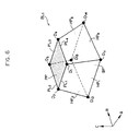
- Fig. 6 shows one example of a basic shape model of one block BL 1 of the pitch group PT 1 .
- One block can be determined by eight points D 1 , D 2 , D 3 , D 4 , D 11 , D 12 , D 13 and D 14 .
- arrow A indicates a tire circumferential direction
- arrow B indicates a tire widthwise direction
- arrow C indicates a tire radial direction.
- PP indicates a ground-contact surface of the one block
- PL 1 , PL 2 , PL 3 and PL 4 indicate lines expressing the ground-contact surface shape
- D 1 , D 2 , D 3 and D 4 indicate vertices of the ground-contact surface which are points of intersection of the lines expressing the ground-contact surface shape.
- the ground-contact surface PP is square, wall surfaces HP 1 , HP 2 , HP 3 and HP 4 are connected to the ground-contact surface PP.
- a bottom surface BP is formed substantially parallel to the ground-contact surface PP, and bottom points D 11 , D 12 , D 13 and D 14 are formed by the wall surfaces and the bottom surface.
- the basic shape model can be divided into a plurality of elements, and may be divided into a plurality of elements by a plurality of normal lines of the tire surface, and may be divided into arbitrary shapes such as triangles depending upon the purpose of design.
- points D 5 , D 6 , D 7 , D 8 , D 51 , D 62 , D 73 and D 84 are set in correspondence to the eight points D 1 , D 2 , D 3 , D 4 , D 11 , D 12 , D 13 and D 14 of the block BL 1 .
- the block BL 3 includes lines PL 5 , PL 6 , PL 7 and PL 8 corresponding to the lines PL 1 , PL 2 , PL 3 and PL 4 expressing the ground-contact surface shape of the block BL 1 .
- the block BL 3 includes vertices D 5 , D 6 , D 7 , D 8 corresponding to vertices D 1 , D 2 , D 3 and D 4 of the ground-contact surface of the block BL 1 .
- Wall surfaces HP 5 , HP 6 , HP 7 and HP 8 are connected to the ground-contact surface of the block BL 3 , in correspondence to the wall surfaces HP 1 , HP 2 , HP 3 and HP 4 connected to the ground-contact surface of the block BL 1 .
- Bottom points D 51 , D 62 , D 73 and D 84 are formed in correspondence to the bottom points D 11 , D 12 , D 13 and D 14 formed by the wall surfaces and the bottom surface of the block BL 1 .
- an objective function representing a physical amount for evaluating a performance of the tire, a constraint condition for limiting the tire shape, and a design variable which determines block shapes, i.e., which determines block shapes of blocks which are elements of the respective pitch groups, are determined.
- the objective function OBJ and the constraint condition G are determined as follows:
- the difference among the block rigidities which is set as the objective function OBJ can be obtained by determining positions of the blocks BL 1 and BL 3 provided on the tire for each of the pitch groups PT 1 and PT 3 and determining for each block the rigidity for each predetermined angle from the rigidity in the tire circumferential direction to the rigidity in the tire widthwise direction by using known equations of rigidity, so as to calculate the difference among the block rigidities by using a value of the difference of the rigidities between the blocks of the pitch groups PT 1 , PT 3 and the dispersion of the differences, e.g., an average value and the deviation.
- the tread thickness which is set as the constraint condition G can be obtained from the volume except the volume required by the blocks BL 1 and BL 3 , i.e., by the volume of the grooves, at the time of forming a tire having the blocks BL 1 and BL 3 provided on the tire. That is, the flow amount of the material such as rubber in a radial direction of tire is determined in accordance with the volume of the grooves, and the tread thickness can be estimated from this value.
- the wall surface angle is used as the design variable and is set by the angle calculating routine shown in Fig. 5.
- a reference point P is set at a predetermined point (the center point of the tire, for example) inside of the tire as shown in Fig.7.
- a range in which it is possible to incline the wall surface of the block is designated as a range which varies the block shape.
- a wall surface of the block is selected by selecting, from the vertices of the ground-contact surface, one group of points which are adjacent to each other.
- the wall surface HP 1 is selected by selecting the points D 1 and D 2 of the block BL 1 in the pitch group PT 1 .
- a ridge line of the selected wall surface (in the example shown in Fig.7, a straight line passing through the line PL 1 from the reference point P), i.e., a straight line in the tire radial direction, is set as a reference line, and an angle ⁇ 1 defined between the reference line and the selected wall surface HP 1 is calculated as shown in Figs. 7 and 8.
- an initial value OBJo of the objective function OBJ and an initial value Go of the constraint condition G at an initial values ro of the design variables r i are calculated in step 104 in Fig.4.
- step 106 in Fig.4 the design variables r i are each continuously varied by ⁇ r i in order to vary the basic shape model.
- the design variables r i are varied, all of the design variables r i may be varied simultaneously, or one of the design variables r i may be varied, or a plurality of design variables among all of the design variables r i may be varied by ⁇ r i simultaneously.
- a shape of each of the blocks formed by angles of the wall surfaces which have been varied by ⁇ r i are determined, i.e., coordinates of each of points D 1 , D 2 , D 3 , D 4 , D 11 , D 12 , D 13 , D 14 and points D 5 , D 6 , D 7 , D 8 , D 51 , D 62 , D 73 , D 84 which have been varied by varying the angle of the wall surface are determined.
- each of block shapes after the design variable has been varied by ⁇ r i i.e., each modified shape model, is determined.
- step 110 a value OBJ i of the objective function and a value G i of the constraint condition, after the design variable has been varied by ⁇ r i with respect to the modified shape model determined in step 108, are calculated.
- next step 114 using the initial value OBJo of the objective function, the initial value Go of the constraint condition, the initial value ro of the design variable, and the sensitivities, there is estimated by mathematical programming a variation amount of the design variable which minimizes the objective function i.e., minimizes the difference among the block rigidities, while satisfying the constraint condition.
- the modified shape models are determined in step 115 by using the same method as that of step 108, and the objective function value is calculated.
- step 116 it is determined whether the objective function value OBJ calculated in step 115 converges on one basis of a threshold value which has been previously input.
- steps 104 to 116 are repeated while taking the design variable obtained in step 114 as the initial value.
- the value of the design variable at that time is determined as the value of the design variable which minimizes the objective function while satisfying the constraint condition, and in step 120, the block shapes forming each pitch of each pitch group are determined by using this design variable value. With these procedures, the shapes of the two pitch groups forming a portion of the tire are determined.
- a block formed with a large number of wall surfaces can be considered to have a ground-contact surface having a plurality of lines representing a ground-contact surface shape formed as a polygon.
- a ground-contact surface PPa of one block has four basic points D 1 , D 2 , D 3 and D 4 .
- points D 21 , D 22 , D 23 and D 24 are formed, and lines PL 21 , PL 22 , PL 23 , PL 24 and PL 25 are formed instead of the line PL 2 connecting the points D 2 and D 3 (Fig.6).
- points D 41 , D 42 , D 43 and D 44 are formed between the points D 1 and D 4 , and lines PL 41 , PL 42 , PL 43 , PL 44 and PL 45 are formed instead of the line PL 4 .
- wall surfaces HP 1 , HP 21 , HP 22 , HP 23 , HP 24 , HP 25 , HP 3 , HP 41 , HP 42 , HP 43 , HP 44 , HP 45 which are continuous from the lines are connected to the ground-contact surface PPa. At least one of these wall surfaces HP 1 to HP 45 can be used as a design variable.
- Fig.10 shows a case in which a ground-contact surface PPb of one block has four basic points D 1 , D 2 , D 3 and D 4 , and the point D 1 side and the point D 4 side are chamfered.
- the chamfering amount it is possible to determine the chamfering amount by determining the coordinates of points D 1A and D 1B , which are to be formed by cutting the angle at the point D 1 side of the block, and the coordinates of points D 3A and D 3B , which are to be formed by cutting the angle at the point D 4 side of the block. Therefore, if the chamfering amount is determined in advance, the positions, i.e., the points to be chamfered can be determined, and at least one of the wall surfaces including a wall surface to be formed by chamfering can be used as a design variable.
- the line forming the wall surface of the block is a straight line
- the line is not be limited to a straight line only, and the line may be a curved line represented by a predetermined function as shown in Fig.11.
- the ground-contact surface PPc of one block has four points D 1 , D 2 , D 3 and D 4 .
- a line PL 1c connecting the points D 1 and D 2 is represented by a predetermined function (e.g., a multidimensional curved line or hyperbola)
- a line PL 3c connecting the points D 3 and D 4 is also represented by a predetermined function (e.g., a multidimensional curved line or hyperbola).
- the curved line shapes of the lines PL 1c and PL 3c may be determined by Lagrangian interpolation, or the curved line itself may be varied as a design variable.
- a wall surface which is continuous from each line of the ground-contact surface PPc becomes a curved surface
- one wall surface may be divided into fine regions (fine planes), and the wall surface may be determined using Lagrangian interpolation or the like.
- the shape of the wall surface itself which is continuous from the ground-contact surface PPd may be a curved surface as shown in Fig.12.
- the rigidities of a single block in the two pitch group can be made uniform in this manner. Therefore, shapes of lug grooves, shapes of rib grooves and the like of the tire can be made appropriately, and shapes at positions in the widthwise direction of a tire can be made appropriately and high level irregular wear resistance and running performance can both be established, in accordance with required performances and the frequency of use during cornering and straight running, without being influenced by the block shape at the ground-contact surface of the tire tread portion.
- an oblique angle can be employed.
- the setting of this design variable is conducted by carrying out the oblique angle calculating routine shown in Fig.13 in place of the processing in Fig. 5.
- a reference point Q is set at a predetermined point (at vertex D 1 in the example shown in Fig.14) of the ground-contact surface of the tire as shown in Fig.14.
- a range in which the line of the ground-contact surface of the block can be inclined is designated as a range in which the block shape (ground contact surface shape) is varied.
- a wall surface of the block is selected by selecting a point for inclining the line among points which are adjacent to the designated vertex of the ground-contact surface.
- the line PL 4 which is continuous with the wall surface HP 4 is selected by selecting the point D 4 .
- an angle ⁇ defined between the selected line PL 4 and a reference line is calculated. This angle ⁇ is the oblique angle.
- next step 158 coordinates of the points D 3 and D 4 defining the lines PL 2 and PL 4 are obtained as variables for varying the oblique angle. Since a length L 1 in the tire widthwise direction and a length L 2 in the tire circumferential direction of this ground-contact surface shape are previously determined, the oblique angle ⁇ must be varied without varying these lengths. To this end, the points D 3 and D 4 may be moved in the tire circumferential direction. The amount of movement S i is set as the design variable ri.
- a sipe has a width ⁇ a and an inclination ⁇ a.
- a sipe has a depth ⁇ b and inclination ⁇ b within the block.
- the sipe need not pass through the block, and as shown in Fig. 17, a sipe has a length ⁇ c when the sipe is formed midway into a block.
- step 310 in Fig.3 it is determined whether the above-described processing has been completed for all of the pitch groups in the pitch array V. When there exists a remaining pitch group, steps 306 to 310 are repeated.
- step 312 the block shape forming each pitch in each pitch group is determined, and the block shapes of all the pitch groups forming the tire are determined, so as to determine the tire shape.
- shapes of lug grooves, shapes of rib grooves and the like of the tire can be made appropriately and a shape at a position in widthwise direction of a tire can be made appropriately, without being influenced by the magnitude of the pitch of the pitch array formed at the tire tread portion. Uneven wear resistance and running performance can both be established at high levels.
- step 320 it is determined whether the above-described process has been completed for all of the pitch groups in the pitch array V.
- step 322 either one of the optimized two pitch groups is set as a reference pitch group.
- step 324 any one of the remaining pitch groups is designated as an optimization pitch group, and the designated optimization pitch group is optimized in next step 326.
- this step 326 only the optimization pitch group is varied for optimization without varying the design variable of the reference pitch group (Fig.4).
- next step 328 it is determined whether optimization has been completed for all of the pitch groups in the pitch array V. When there exists remaining pitch group(s), steps 324 to 328 are repeated.
- the procedure is advanced to step 330, the block shape forming each pitch in each pitch group is determined, and the block shapes of all the pitch groups forming the tire are determined, so as to thereby determine the tire shape.
- the shapes of lug grooves, the shapes of the rib grooves and the like of the tire can be made appropriately and appropriateness in the widthwise direction of the tire can be acheived, without being influenced by the magnitude of the pitch of the pitch array formed in the tire tread portion and without varying the values of rigidities of the blocks. Wear resistance and running performance of the tire can be established at high levels.
- the values of the block rigidities to be uniformized may vary widely. Therefore, differences in rigidities may be uniformized stably.
- an arbitrary pitch group may be determined as a reference pitch group of the tire 20, and the other pitch group may be optimized so as to uniformize the differences in rigidity with respect to the reference pitch group.
- a pitch group which is obtained by data determined previously by experimentation may be used as the arbitrary pitch group.
- the block rigidities may be determined in advance, and at these block rigidities, differences in the rigidities of the two pitch groups may be made uniform.
- the present embodiment is to design the block shape of a tire by a genetic algorithm.
- a design variable which is different from the above-described embodiments may be used. Since the present embodiment is structured substantially the same as the above-described embodiments, the same elements are denoted by the same reference symbols, and their detailed descriptions will be omitted.
- Fig. 19 shows a processing routine of a program of the present embodiment.
- step 200 each of the block shapes of a plurality of pitch groups included in the pitch array v is modeled into N block shapes by a technique which can numerically and analytically obtain the block rigidity of the tire such as the finite element method, to thereby obtain a tire basic shape model including an internal structure.
- N is previously input by a user.
- One block shape model of the tire basic shape model used in the present embodiment is the same as that shown in Fig. 6 of the first embodiment.
- an objective function representing a physical amount for evaluating performance of the tire, a constraint condition for limiting the tire shape, and a design variable for determining each of the block shapes of N tire shape models are determined.
- the objective function OBJ and the constraint condition G are determined as follows.
- Constraint condition G Tread thicknesses constraining the tire shape are made uniform.
- a wall surface angle which is the design variable is determined for each of the N tire shape models by the angle calculation routine in Fig. 5, as described in the first embodiment. Since this process is the same as that of the first embodiment, description thereof will be omitted.
- an adaptive function F J of each of the N shape models is calculated in accordance with the following equation (4).
- the value of the adaptive function (fitness) increases as the difference in the block rigidities or the difference in the standard deviations of the block rigidity decreases.
- ⁇ J - OBJ J + ⁇ ⁇ max (G J , O)
- next step 208 two tire shape models for crossing are selected from the N tire shape models.
- a generally known fitness proportion strategy is used as the method of selection.
- the probability Pe that a certain model e will be selected from the N shape models is represented by the following equation: wherein
- fitness proportion strategy is used as the selecting method in the present embodiment, other strategies may be used such as expected value strategy, rank strategy, elite conservation strategy, tournament selection strategy, GENITOR algorithm and the like, as set forth in "Genetic Algorithm” edited by Hiroaki Kitano.
- next step 210 it is determined whether the selected two tire shape models should be crossed by the probability T which is input in advance by the user.
- cross means that portions of elements of the two tire shape models are exchanged, as will be described later. If the determination is negative, i.e . , if the selected two tire shape models should not be crossed, the routine proceeds as is to step 216. On the other hand, if the determination is affirmative, i.e., if the selected two tire shape models should be crossed, the two tire shape models are crossed in step 214 as will be described later.
- step 250 in Fig. 2 previously determined random numbers are generated, and a crossing location i concerning the design variable vectors of the tire shape models a and b is determined in accordance with the random numbers.
- d
- r i ' a r i a -min(
- r i ' b r i b +min(
- )/0.5 ⁇ Z ab or, r i ' a r i a +min(
- r i ' b r i b -min(
- Vr' a and Vr' b which are rows of the new design variables are obtained as follows:
- Vr' a (r 1 a , r 2 a , ... r i ' a , r i+1 b , ..., r n-1 b )
- Vr' b (r 1 b , r 2 b , ... r i ' b , r i+1 a , ..., r n-1 a )
- the minimum value B L and the maximum value B U in the possible range of r i are input in advance by the user.
- the map function Z(x) may be a valley shaped function as shown in Figs.23A and 23B. In the above described example, there is one crossing location i, but a plurality of crossings or an even crossing may be used as set forth in "Genetic Algorithm" edited by Hiroaki Kitano.
- step 216 in Fig.19 it is determined whether a mutation should be carried out at the probability S which is input in advance by the user.
- the term "mutation" means that a portion of the design variable is finely varied as will be described later, so as to increase the probability of including a population which can be an optimal design variable. If the determination in step 216 is negative, i.e., if no mutation is to be carried out, in step 226, the current two tire shape models are maintained as they are, and the procedure is advanced to next step 222. If the determination in step 216 is affirmative, i .e., if a mutation is to be carried out, a mutation is carried out in step 220 in the following manner.
- the mutation is carried out by the mutation routine shown in Fig. 21.
- random numbers are generated in step 262, and a location i for mutation is determined by the random numbers.
- a distance d' is determined by the random numbers within the following range: 0 ⁇ d' ⁇ 1
- )/0.5 ⁇ Zd or, r i ' r i +min(
- a value of the objective function and a value of the constraint condition are calculated in step 222 in Fig. 2 9 for the two tire shape models which have been newly created in this manner.
- an adaptive function is calculated by using equation (4) in the same manner as that in the previously-described embodiment, from the obtained value of the objective function and value of the constraint condition.
- next step 226 the two tire shape models are stored.
- step 230 if any one of the following constraint conditions is satisfied, it is determined that there is convergence.
- M, q and p are input in advance by the user.
- the groove wall angle is optimized to uniformize the tread thickness. Since the present embodiment is structured substantially the same as the previous embodiments, the same portions are denoted by the same reference symbols, and their detailed descriptions will be omitted.
- the block shape has a long side having a length LB in the tire circumferential direction, and a short side having a length LA in the tire widthwise direction which is perpendicular to the tire circumferential direction, and a height DP.
- the groove wall angles of the groove walls HP 1 and HP 3 which are continuous with the short sides having the length LA are both set to ⁇ .
- the groove wall angles of the groove walls HP 2 and HP 4 which are continuous with the long sides having the length LB are both set to ⁇ .
- the groove wall angles ⁇ and ⁇ of the block are optimized as described in the previous embodiments.
- the objective function OBJ and the constraint condition G are set as follows:
- the tread thickness of the pitches or the pitch groups can be made uniform, unevenness of the tire tread thickness can be overcome without being influenced by the magnitudes of the pitches of the pitch array formed at the tire tread portion.
- the difference in tread thickness at this time improved to 0.01 mm whereas the conventional difference was 0.08 mm.
- Figs. 25A and 25B show rigidities per unit area with respect to direction, i.e., Fig. 25A shows conventional rigidities before optimization for uniformizing the thickness of a tread, and Fig. 25B shows rigidities after optimization for uniformizing the thickness of a tread according to the present embodiment.
- uniformity of the tire shape is uniformized, and as can be understood from Figs. 25A and 25B, the difference in rigidities of pitches substantially coincides with or is even slightly enhanced over the conventional shape.
- a fifth embodiment will be described next.
- the present embodiment is to optimize the groove wall angle to uniformize the tread thickness and to uniformize the differences between rigidities of pitches or pitch groups. Since the present embodiment is structured substantially the same as the above-described embodiments, the same portions are denoted by the same reference symbols, and their detailed descriptions will be omitted.
- the groove wall angle When the groove wall angle is optimized, since a distance between adjacent blocks and the groove depth also is determined by the pitch array, the groove wall angle has a range in which the angle can vary. Accordingly, there are limits to the optimization by only the groove wall angle.
- an amount of bottom raise is introduced into the design variable.
- a tire 20 which is determined by the pitch array V of the present embodiment comprises three kinds of pitches, i.e., a small pitch Y 1 , a medium pitch Y 2 and a large pitch Y 3 .
- a pitch group PT 1 in which eight small pitches Y 1 are continuously arranged
- a pitch group PT 2 in which four medium pitches Y 2 are continuously arranged
- a pitch group PT 3 in which five large pitches Y 3 are continuously arranged.
- the pitch array V is formed such that pitch groups PT 2 , PT 3 , PT 2 , PT 1 , PT 2 , PT 3 , PT 2 , PT 1 , PT 2 , PT 3 , PT 2 and PT 1 are arranged continuously in a clockwise direction on the tire 20.
- each of the pitch groups PT 1 , PT 2 and PT 3 comprises a plurality of pitch in which the small pitch Y 1 , the medium pitch Y 2 and the large pitch Y 3 are arranged continuously
- the present invention should not be limited to this only, and each of pitch groups PT 1 , PT 2 , PT 3 may comprise a single pitch. That is, at least one of the pitch groups PT 1 , PT 2 , PT 3 may only comprise any one of the small pitch Y 1 , the medium pitch Y 2 and the large pitch Y 3 .
- the groove wall angle and the amount of bottom raise are optimized, and optimization is conducted to uniformize the tread thickness and to uniformize the differences between rigidities of the pitches or pitch groups.
- the amount of bottom raise is further added as a design variable to the design variables of the previously-described embodiments.
- the tread thickness and the differences between rigidities of the pitches or pitch groups can be uniformized among each of the pitches or each of the pitch groups, unevenness of the tire tread thickness can be overcome without being influenced by the magnitude of the pitches of the pitch array formed at the tire tread portion, and differences between rigidities of the pitches or pitch groups can be uniformized.
- the difference in tread thickness at that time was 0.01 mm.
- Fig. 28 shows a rigidities per unit area with respect to direction. As can be understood from the drawing, uniformity of tire shape is uniformized, and the differences in rigidities of pitches are made to substantially coincide.
- Fig. 29 shows the results.
- Fig. 29A shows the results of RFV (speed: 10 km/h)
- Fig. 29B shows the results of high speed RFV (speed: 120 km/h)
- Fig. 29C shows the results of high speed TFV (speed: 10 km/h)
- Fig. 29D shows the results of LFV (speed: 120 km/h), where RFV means radial force variation, TFV means tangential force variation, and LFV means lateral force variation.
- the bars with slanted lines show the results of a conventional tire
- the white bars show the results of the tire to which the present embodiment is applied.
- the tire according to the present embodiment is improved by 11% to 50% as compared with the conventional tire.
- the tire was mounted to a vehicle, steering stability was measured, and as a result, it was found that the steering stability was improved by 6.5 whereas the conventional steering stability was 5.5.
- the groove wall angle and the bottom raise amount and optimizing in order to uniformize the tread thickness and differences between rigidities of pitches or pitch groups as in the present embodiment the small pitch was enhanced by 3452 N (352.0 kgf), and difference between rigidities was enhanced by 1N (0.1 kgf.)
- the present inventor tested the effect of uniformizing the tread thickness.
- a tire was prepared according to the design of the present embodiment in the same way as described above, and the tread thickness was measured.
- Fig. 30 shows the results.
- the conventional tire had 0 .12 mm variability in tread thickness
- the tire of the present invention had 0.05 mm variability in tread thickness including a measuring error of about 0.02 mm.
- straight pushing loads of 20 mm were compared. This test was conducted by using FEM analysis. If the tread thickness was increased by 0.1 mm, the rigidity increased from 3452 N (352.1 kgf) to 3466 N (353.4 kgf), i.e., the rigidity increased by 14 N (1.3 kgf.)
- Figs. 31A and 31B are diagrams showing rigidities per unit area with respect to direction, i.e., Fig. 31A shows conventional rigidities, and Fig. 31B shows rigidities after optimization according to present embodiment for uniformizing both tread thickness and rigidity. As can be understood from Figs. 31A and 31B, differences between rigidities of pitches substantially coincide as compared with the conventional tire.
- the tire 20 determined by a pitch array V shown in Fig. 27 is employed.
- a pitch array V shown in Fig. 27 As one example, a case in which a 195/65R14 tire having a groove depth of 7.0 is used is described.
- a rhombic block among rectangular blocks is used.
- Fig. 32 shows a tread pattern in which a small pitch Y 1 , a medium pitch Y 2 and a large pitch Y 3 are continuously arranged.
- a block BL S of the small pitch Y 1 has a length LX 1 in the tire widthwise direction and a length LY 1 in the tire circumferential direction.
- a block BL M of the medium pitch Y 2 has a length LX 2 in the tire widthwise direction and a length LY 2 in the tire circumferential direction.
- a block BL L of the large pitch Y 3 has a length LX 3 in the tire widthwise direction and a length LY 3 in the tire circumferential direction.
- Fig. 33A shows one example of the block BL S of the small pitch Y 1 and the block BL L of the large pitch Y 3 . Since the block is rhombic, it has four angles, and opposed angles have substantially the same shapes. As shown in Fig. 33B, the two tire widthwise direction angles of the block BLs of the small pitch Y 1 are chamfered, and the two tire circumferential direction angles of the block BL L of the large pitch Y 3 are chamfered.
- the chamfering is conducted such that the chamfering is started from a position at a predetermined length LZ along a ridge line from the ground-contact surface side point D 1 among the vertexes D 1 and D 11 before chamfering, and the block is cut toward the tread side point D 11 .
- uniformity of differences between rigidities of the blocks can be improved.
- the present invention is not limited to the same, and chamfering can be conducted for at least one of the tire circumferential direction and the tire widthwise direction for each of the blocks.
- the chamfering method is not limited to cutting toward the tread side point D 11 , and the block may be cut at a depth equal to the predetermined length LZ along the ridge line, or may be cut to a predetermined depth.
- the blocks are chamfered in the tire circumferential direction.
- the blocks BL S of the small pitch Y 1 were not chamfered.
- the blocks BL M of the medium pitch Y 2 were chamfered 2mm at the angles in the tire circumferential direction, and the blocks BL L of the large pitch Y 3 were chamfered 5mm at the angles in the tire circumferential direction.
- Fig. 35A shows rigidities of blocks per unit area with respect to each of the small pitch and large pitch of a normal design without chamfering
- Fig. 35B shows rigidities of blocks per unit area with respect to each of the chamfered small pitch and large pitch according to the present example.
- uniformity of the block rigidities is enhanced.
- the present inventor applied the above-described blocks to a tire and carried out tests. As a result of measurement of indoor uniformity, it was found that the third degree component was enhanced, RFV was enhanced by 10%, and TFV was enhanced by 15%. Further, the tire was mounted to a vehicle and steering stability was measured, and as a result, it was found that the steering stability was enhanced by 5.5 whereas the conventional steering stability was 5.0.
- blocks were chamfered in the tire widthwise direction.
- blocks BL L of the large pitch Y 3 were not chamfered.
- Blocks BL S of the small pitch Y 1 were chamfered 2 mm at the angles in the tire widthwise direction, and blocks BL M of the medium pitch Y 2 were chamfered 0.8 mm at the angles in the tire widthwise direction.
- Fig. 37A shows rigidities of blocks per unit area with respect to each of the small pitch and large pitch of a normal design without chamfering
- Fig. 37B shows rigidities of blocks per unit area with respect to each of the chamfered small pitch and large pitch according to the present example.
- uniformity of the block rigidities is enhanced.
- the present inventor applied the above-described blocks to a tire and carried out tests. As a result of measurement of indoor uniformity, it was found that the third degree component was enhanced, RFV was enhanced by 10%, and TFV was enhanced by 10%. Further, the tire was mounted to a vehicle and steering stability was measured, and as a result, it was found that the steering stability was enhanced by 5.25 whereas the conventional steering stability was 5.0.
- blocks of an actual tire were chamfered.
- a 275/40ZR18 type tire having a one side tread width of 140 mm and a pitch length of 50.91:80.01 was employed.
- blocks BL S of the small pitch Y 1 were chamfered Ms by 2 mm at angles in the tire widthwise direction. That is, as shown in left side in Fig. 33B, the two angles in the tire widthwise direction of each of the blocks of the small pitch Y 1 were chamfered. Further, as shown in Fig. 39, at blocks BL M of the medium pitch Y 2 , angles in the tire widthwise direction were chamfered Mm 2 by 1 mm, and angles in the tire circumferential direction were chamfered Mm 1 by 2 mm.
- the present inventor measured the steering stability for a tire which was chamfered as described above and which was mounted to a vehicle. As a result, it was found that the steering stability was enhanced by 6.5 whereas the conventional steering stability was 5.5.
- the block rigidity is made the same level, and deformation of the block and generation of force in each of the pitches are made to approach the same direction.
- the method for designing a pneumatic tire according to the present invention is optimal for use in designing a tire of a pitch array comprising a plurality of pitches for example, and is especially suitable for use in designing to uniformize the rigidities and uniformity which are assumed to cause variation in shape.
Landscapes
- Engineering & Computer Science (AREA)
- Mechanical Engineering (AREA)
- Tires In General (AREA)
Claims (12)
- Procédé pour concevoir un bandage pneumatique, comprenant les étapes consistant à :(1) sélectionner un élément parmi :une forme d'un bloc seul comprenant une structure interne ;une forme de motif d'une partie d'une portion de sommet d'un pneumatique comprenant une structure interne, etune forme d'une portion de méplat qui est continue dans une direction circonférentielle du pneumatique comprenant une structure interne ;(2) déterminer un modèle de base de pneumatique comprenant une pluralité de modèles différents de forme de base en se basant sur la forme sélectionnée à l'étape (1);(3) déterminer une fonction d'objectif représentant une quantité physique d'évaluation de performances d'un pneumatique ;(4) déterminer une variable de conception pour déterminer la forme des modèles de forme de base ;(5) déterminer une condition de contrainte qui restreint au moins un élément parmi :la forme d'un bloc seul comprenant une structure interne,la forme de motif d'une partie d'une portion de sommet d'un pneumatique comprenant une structure interne, etla forme d'une portion de méplat qui est continue dans une direction circonférentielle du pneumatique comprenant une structure interne,et qui restreint au moins un élément parmi :une forme en coupe d'un pneumatique, etla quantité physique d'évaluation de performances d'un pneumatique ;(6) faire varier la valeur de ladite variable de conception d'au moins un modèle de forme de base ;(7) déterminer une valeur de ladite variable de conception d'au moins un modèle de forme de base, au moyen de laquelle une valeur optimale de ladite fonction d'objectif est obtenue, pendant que ladite condition de contrainte est satisfaite, à partir des valeurs modifiées de ladite variable de conception d'au moins un modèle de forme de base ; et(8) concevoir ledit bandage pneumatique sur la base de la valeur déterminée de ladite variable de conception.
- Procédé selon la revendication 1, dans lequel :à l'étape (6), des valeurs de la variable de conception de deux modèles de forme de base varient ;à l'étape (7), les valeurs respectives de la variable de conception des deux modèles de base est déterminée.
- Procédé selon la revendication 1, dans lequel :à l'étape (6), une valeur de la variable de conception d'un parmi la pluralité de modèles différents de forme de base varie ;à l'étape (7), une valeur de la variable de conception d'un parmi la pluralité de modèles différents de forme de base est déterminée.
- Procédé selon la revendication 1 à 3, dans lequel la variable de conception sert à déterminer une autre forme du bloc seul, une autre forme de motif ou une autre forme de la portion de méplat, en utilisant au moins un des différents modèles de forme de base comme modèle de forme de référence.
- Procédé selon l'une quelconque des revendications 1 à 3, dans lequel la forme du bloc seul, la forme de motif ou la forme de la portion de méplat est déterminée en utilisant un modèle prédéterminé de forme de base parmi la pluralité de modèles différents de forme de base comme modèle de référence.
- Procédé selon l'une quelconque des revendications 1 à 5, dans lequel une quantité de variation de la variable de conception qui donne la valeur optimale de la fonction d'objectif tout en tenant compte de la condition de contrainte est estimée en se basant sur une sensibilité de la fonction d'objectif, qui est un rapport d'une quantité unitaire de variation de la variable de conception à une quantité de variation de la fonction d'objectif, et en se basant sur une sensibilité de la condition de contrainte, qui est un rapport d'une quantité unitaire de variation de la variable de conception à une quantité de variation de la condition de contrainte ; une valeur de la fonction d'objectif quand la variable de conception varie d'une quantité correspondant à la quantité estimée est calculée, et une valeur de la condition de contrainte obtenue quand la variable de conception varie d'une quantité correspondant à la quantité estimée est calculée ; et une valeur de la variable de conception qui donne la valeur optimale de la fonction d'objectif tout en tenant compte de la condition de contrainte est déterminée sur la base de la valeur estimée et des valeurs calculées.
- Procédé selon l'une quelconque des revendications 1 à 5, dans lequel un groupe de sélection comprenant une pluralité de modèles de base de pneumatique comprenant une pluralité de modèles différents de forme de base représentant une forme sélectionnée parmi une forme d'un bloc seul comprenant une structure interne, une forme de motif d'une partie d'une portion de sommet d'un pneumatique comprenant une structure interne, et une forme d'une portion de méplat qui est continue dans une direction circonférentielle du pneumatique comprenant une structure interne est déterminée ; et pour chacun des modèles de base de pneumatique du groupe de sélection, la fonction d'objectif, la variable de conception, la condition de contrainte, et une fonction adaptative qui peut être évaluée à partir de la fonction d'objectif et de la condition de contrainte, sont déterminées ; et
deux modèles de base de pneumatique sont sélectionnés dans le groupe de sélection sur la base de la fonction adaptative ; des variables de conception des modèles de base de pneumatique sont croisées à une probabilité prédéterminée pour créer un nouveau modèle de base de pneumatique, et/ou une portion de la variable de conception d'au moins un des modèles de base de pneumatique est modifiée pour créer un nouveau modèle de base de pneumatique ; une fonction d'objectif, une condition de contrainte et une fonction adaptative du modèle de base de pneumatique dont la variable de conception a été modifiée sont déterminées, le modèle de base de pneumatique dont la variable de conception a été modifiée et un modèle de base de pneumatique dont la variable de conception n'a pas été modifiée sont stockés, les opérations ci-dessus sont répétées jusqu'à ce que le nombre de modèles de base de pneumatique atteigne une valeur prédéterminée, on détermine si un nouveau groupe comprenant le nombre prédéterminé de modèles de base de pneumatique stockés satisfait à une condition prédéterminée de convergence, et quand la condition de convergence n'est pas satisfaite, les opérations ci-dessus sont répétées en utilisant le nouveau groupe comme groupe de sélection, jusqu'à ce que le groupe de sélection satisfasse la condition de convergence, et quand la condition de convergence est satisfaite, une valeur de la variable de conception qui donne la valeur optimale de la fonction d'objectif tout en tenant compte de la condition de contrainte est déterminée à partir du nombre prédéterminé de modèles de base de pneumatique stockés. - Procédé selon l'une quelconque des revendications 1 à 7, dans lequel la variable de conception comprend une variable qui représente au moins un élément parmi : un angle d'une surface reliée à une surface de la portion de méplat du pneumatique qui est formée par une forme sélectionnée parmi la forme du bloc seul, la forme du motif, et la forme de la portion de méplat ; une hauteur jusqu'à la surface de la portion de méplat du pneumatique ; une forme d'une surface de la portion de méplat du pneumatique ; une forme d'une surface reliée à une surface de la portion de méplat du pneumatique ; une position d'une lamelle ; un nombre de lamelles ; la largeur d'une lamelle ; la profondeur d'une lamelle ; l'inclinaison d'une lamelle ; la forme d'une lamelle ; la forme longitudinale d'une lamelle.
- Procédé selon l'une quelconque des revendications 1 à 8, dans lequel chacun des modèles de base de pneumatique comprenant une pluralité de modèles de forme de base a une longueur différente dans la direction circonférentielle du pneumatique.
- procédé selon la revendication 1, dans lequel la forme du bandage pneumatique est conçue en se basant sur le modèle de base de pneumatique comprenant un modèle de forme de base de petit pas et un modèle de forme de base de grand pas comme modèle de forme d'une portion d'un sommet de pneumatique comprenant une structure interne et une forme de portion de bord qui est continue dans une direction circonférentielle du pneumatique comprenant une structure interne, et quand les blocs comprennent un angle dans au moins une direction circonférentielle et dans une direction transversale, des angles dans la direction transversale de blocs de petit pas sont chanfreinés, et des angles dans la direction transversale du grand pas sont chanfreinés.
- Procédé selon la revendication 10, dans lequel des angles dans la direction transversale du grand pas sont plus petits que des angles dans la direction transversale du petit pas, et/ou des angles dans la direction circonférentielle du petit pas sont plus petits que des angles dans la direction circonférentielle du grand pas.
- Procédé selon la revendication 10 ou 11, dans lequel un pas moyen est prévu entre le grand pas et le petit pas.
Applications Claiming Priority (3)
| Application Number | Priority Date | Filing Date | Title |
|---|---|---|---|
| JP35072096 | 1996-12-27 | ||
| JP35072096 | 1996-12-27 | ||
| PCT/JP1997/004883 WO1998029270A1 (fr) | 1996-12-27 | 1997-12-26 | Procedes pour conception de pneumatiques |
Publications (3)
| Publication Number | Publication Date |
|---|---|
| EP0924111A1 EP0924111A1 (fr) | 1999-06-23 |
| EP0924111A4 EP0924111A4 (fr) | 2000-06-28 |
| EP0924111B1 true EP0924111B1 (fr) | 2004-09-29 |
Family
ID=18412399
Family Applications (1)
| Application Number | Title | Priority Date | Filing Date |
|---|---|---|---|
| EP97949252A Expired - Lifetime EP0924111B1 (fr) | 1996-12-27 | 1997-12-26 | Procedes pour conception de pneumatiques |
Country Status (5)
| Country | Link |
|---|---|
| EP (1) | EP0924111B1 (fr) |
| JP (1) | JP4393590B2 (fr) |
| DE (1) | DE69730979T2 (fr) |
| ES (1) | ES2229392T3 (fr) |
| WO (1) | WO1998029270A1 (fr) |
Families Citing this family (17)
| Publication number | Priority date | Publication date | Assignee | Title |
|---|---|---|---|---|
| JP3238376B2 (ja) * | 1998-12-28 | 2001-12-10 | 住友ゴム工業株式会社 | 空気入りタイヤ |
| JP2001287516A (ja) * | 2000-04-04 | 2001-10-16 | Bridgestone Corp | タイヤの設計方法、タイヤ用加硫金型の設計方法、タイヤ用加硫金型の製造方法、タイヤの製造方法、タイヤの最適化解析装置及びタイヤの最適化解析プログラムを記録した記憶媒体 |
| DE60122975T2 (de) * | 2000-07-06 | 2006-12-28 | Sumitomo Rubber Industries Ltd., Kobe | Luftreifen |
| US7133736B2 (en) | 2000-07-11 | 2006-11-07 | Pirelli Pneumatici S.P.A. | Method for designing a tire and method for producing at least one tire |
| EP1440789B1 (fr) * | 2000-07-11 | 2007-04-25 | Pirelli Tyre S.p.A. | Procédé de production de pneumatiques |
| US6520230B1 (en) * | 2000-09-06 | 2003-02-18 | The Goodyear Tire & Rubber Company | Tire with an open tread |
| WO2002024473A1 (fr) * | 2000-09-19 | 2002-03-28 | Michelin Recherche Et Technique S.A. | Procede de conception d'un pneu a bruit de cavite reduit et pneu conçu selon le procede |
| US7073382B2 (en) | 2000-09-19 | 2006-07-11 | Michelin Recherehe Et Technique, S.A. | Method for designing a tire with reduced cavity noise |
| US7090735B2 (en) * | 2001-08-06 | 2006-08-15 | Bridgestone/Firestone North American Tire, Llc | Method of compensating for residual aligning torque (RAT) |
| JP2003072319A (ja) * | 2001-09-06 | 2003-03-12 | Toyo Tire & Rubber Co Ltd | 空気入りタイヤ |
| JP4072097B2 (ja) * | 2003-05-29 | 2008-04-02 | 住友ゴム工業株式会社 | 高速fv低減タイヤの製造方法 |
| JP4525263B2 (ja) * | 2004-09-14 | 2010-08-18 | 横浜ゴム株式会社 | タイヤ接地状態における物理量取得方法 |
| JP4736645B2 (ja) * | 2005-09-06 | 2011-07-27 | 横浜ゴム株式会社 | 空気入りタイヤ |
| JP4943799B2 (ja) * | 2006-10-04 | 2012-05-30 | 株式会社ブリヂストン | タイヤモデル作成方法、タイヤモデル作成装置、及びタイヤモデル作成プログラム |
| JP5236301B2 (ja) * | 2007-04-13 | 2013-07-17 | 東洋ゴム工業株式会社 | タイヤの設計方法 |
| JP6476565B2 (ja) * | 2013-09-30 | 2019-03-06 | 横浜ゴム株式会社 | ピッチ配列の決定方法、ピッチ配列の決定装置、ピッチ配列の決定プログラム |
| MX2020010650A (es) * | 2018-04-18 | 2021-01-15 | Pirelli | Metodo para elaborar neumaticos verdes. |
Family Cites Families (11)
| Publication number | Priority date | Publication date | Assignee | Title |
|---|---|---|---|---|
| JPS62157810A (ja) * | 1985-12-30 | 1987-07-13 | Yokohama Rubber Co Ltd:The | 空気入りタイヤ |
| JPH01195103A (ja) * | 1988-01-27 | 1989-08-07 | Sumitomo Rubber Ind Ltd | ラジアルタイヤ |
| JP2819510B2 (ja) * | 1988-11-04 | 1998-10-30 | 住友ゴム工業 株式会社 | 自動車用タイヤ |
| JP2702758B2 (ja) * | 1988-11-30 | 1998-01-26 | 住友ゴム工業株式会社 | 空気入りタイヤ |
| JPH0392403A (ja) * | 1989-09-04 | 1991-04-17 | Bridgestone Corp | サイプつきブロックパターンを有する空気入りタイヤ |
| JP2702873B2 (ja) * | 1992-09-16 | 1998-01-26 | 住友ゴム工業株式会社 | ラジアルタイヤ |
| ES2134341T3 (es) * | 1993-01-27 | 1999-10-01 | Bridgestone Corp | Procedimiento para el diseño de una cubierta de neumatico. |
| JP3432573B2 (ja) * | 1993-06-10 | 2003-08-04 | 株式会社ブリヂストン | タイヤのピッチ配列決定方法 |
| JP3686107B2 (ja) * | 1993-10-06 | 2005-08-24 | 株式会社ブリヂストン | 空気入りタイヤの設計方法 |
| JP2892924B2 (ja) * | 1993-11-30 | 1999-05-17 | 住友ゴム工業株式会社 | 低騒音タイヤ |
| JPH07186623A (ja) * | 1993-12-27 | 1995-07-25 | Yokohama Rubber Co Ltd:The | 空気入りタイヤ |
-
1997
- 1997-12-26 DE DE69730979T patent/DE69730979T2/de not_active Expired - Lifetime
- 1997-12-26 EP EP97949252A patent/EP0924111B1/fr not_active Expired - Lifetime
- 1997-12-26 JP JP52986498A patent/JP4393590B2/ja not_active Expired - Fee Related
- 1997-12-26 ES ES97949252T patent/ES2229392T3/es not_active Expired - Lifetime
- 1997-12-26 WO PCT/JP1997/004883 patent/WO1998029270A1/fr active IP Right Grant
Also Published As
| Publication number | Publication date |
|---|---|
| WO1998029270A1 (fr) | 1998-07-09 |
| ES2229392T3 (es) | 2005-04-16 |
| EP0924111A1 (fr) | 1999-06-23 |
| DE69730979T2 (de) | 2005-02-10 |
| EP0924111A4 (fr) | 2000-06-28 |
| JP4393590B2 (ja) | 2010-01-06 |
| DE69730979D1 (de) | 2004-11-04 |
Similar Documents
| Publication | Publication Date | Title |
|---|---|---|
| US6531012B2 (en) | Pneumatic tire designing method | |
| EP0924111B1 (fr) | Procedes pour conception de pneumatiques | |
| EP1030170B1 (fr) | Prediction de la performance d'un pneu | |
| EP0642916B1 (fr) | Procede de conception concernant un pneumatique | |
| EP1939774B1 (fr) | Procédé de modélisation d'un modèle de pneumatique et procédé de simulation | |
| JP3432573B2 (ja) | タイヤのピッチ配列決定方法 | |
| JP4156870B2 (ja) | タイヤの性能予測方法及びタイヤの設計方法 | |
| JP4888227B2 (ja) | データ解析プログラム、データ解析装置、構造体の設計プログラム、および構造体の設計装置 | |
| US20010032691A1 (en) | Tire | |
| JP5018116B2 (ja) | タイヤの設計方法およびタイヤの設計装置 | |
| US5394916A (en) | Multiple tread geometries for reduced tire tread noise | |
| Nakajima et al. | Theory of optimum tire contour and its application | |
| US7280951B2 (en) | Method of making finite element model of tire having fine groove | |
| KR100541924B1 (ko) | 공기타이어의설계방법 | |
| KR100553229B1 (ko) | 공기타이어의설계방법 | |
| JP4656952B2 (ja) | 変動量算出装置 | |
| AU705693B2 (en) | Pneumatic tire | |
| JP6088135B2 (ja) | 空気入りタイヤ | |
| JP2001080315A (ja) | 空気入りタイヤ | |
| CN115991062A (zh) | 充气轮胎 |
Legal Events
| Date | Code | Title | Description |
|---|---|---|---|
| PUAI | Public reference made under article 153(3) epc to a published international application that has entered the european phase |
Free format text: ORIGINAL CODE: 0009012 |
|
| 17P | Request for examination filed |
Effective date: 19980828 |
|
| AK | Designated contracting states |
Kind code of ref document: A1 Designated state(s): DE ES FR GB IT |
|
| A4 | Supplementary search report drawn up and despatched |
Effective date: 20000516 |
|
| AK | Designated contracting states |
Kind code of ref document: A4 Designated state(s): DE ES FR GB IT |
|
| 17Q | First examination report despatched |
Effective date: 20020610 |
|
| GRAP | Despatch of communication of intention to grant a patent |
Free format text: ORIGINAL CODE: EPIDOSNIGR1 |
|
| GRAS | Grant fee paid |
Free format text: ORIGINAL CODE: EPIDOSNIGR3 |
|
| GRAA | (expected) grant |
Free format text: ORIGINAL CODE: 0009210 |
|
| AK | Designated contracting states |
Kind code of ref document: B1 Designated state(s): DE ES FR GB IT |
|
| REG | Reference to a national code |
Ref country code: GB Ref legal event code: FG4D |
|
| REF | Corresponds to: |
Ref document number: 69730979 Country of ref document: DE Date of ref document: 20041104 Kind code of ref document: P |
|
| REG | Reference to a national code |
Ref country code: ES Ref legal event code: FG2A Ref document number: 2229392 Country of ref document: ES Kind code of ref document: T3 |
|
| ET | Fr: translation filed | ||
| PLBE | No opposition filed within time limit |
Free format text: ORIGINAL CODE: 0009261 |
|
| STAA | Information on the status of an ep patent application or granted ep patent |
Free format text: STATUS: NO OPPOSITION FILED WITHIN TIME LIMIT |
|
| 26N | No opposition filed |
Effective date: 20050630 |
|
| PGFP | Annual fee paid to national office [announced via postgrant information from national office to epo] |
Ref country code: GB Payment date: 20101222 Year of fee payment: 14 |
|
| PGFP | Annual fee paid to national office [announced via postgrant information from national office to epo] |
Ref country code: ES Payment date: 20111228 Year of fee payment: 15 |
|
| GBPC | Gb: european patent ceased through non-payment of renewal fee |
Effective date: 20121226 |
|
| PG25 | Lapsed in a contracting state [announced via postgrant information from national office to epo] |
Ref country code: GB Free format text: LAPSE BECAUSE OF NON-PAYMENT OF DUE FEES Effective date: 20121226 |
|
| PGFP | Annual fee paid to national office [announced via postgrant information from national office to epo] |
Ref country code: DE Payment date: 20131220 Year of fee payment: 17 |
|
| PGFP | Annual fee paid to national office [announced via postgrant information from national office to epo] |
Ref country code: IT Payment date: 20131218 Year of fee payment: 17 |
|
| REG | Reference to a national code |
Ref country code: ES Ref legal event code: FD2A Effective date: 20140509 |
|
| PG25 | Lapsed in a contracting state [announced via postgrant information from national office to epo] |
Ref country code: ES Free format text: LAPSE BECAUSE OF NON-PAYMENT OF DUE FEES Effective date: 20121227 |
|
| PGFP | Annual fee paid to national office [announced via postgrant information from national office to epo] |
Ref country code: FR Payment date: 20131220 Year of fee payment: 17 |
|
| REG | Reference to a national code |
Ref country code: DE Ref legal event code: R082 Ref document number: 69730979 Country of ref document: DE Representative=s name: HOFFMANN - EITLE, DE |
|
| REG | Reference to a national code |
Ref country code: FR Ref legal event code: CA Effective date: 20140812 |
|
| REG | Reference to a national code |
Ref country code: DE Ref legal event code: R082 Ref document number: 69730979 Country of ref document: DE Representative=s name: HOFFMANN - EITLE PATENT- UND RECHTSANWAELTE PA, DE Effective date: 20140828 Ref country code: DE Ref legal event code: R082 Ref document number: 69730979 Country of ref document: DE Representative=s name: HOFFMANN - EITLE, DE Effective date: 20140828 Ref country code: DE Ref legal event code: R081 Ref document number: 69730979 Country of ref document: DE Owner name: BRIDGESTONE CORPORATION, JP Free format text: FORMER OWNER: BRIDGESTONE CORP., TOKIO/TOKYO, JP Effective date: 20140828 |
|
| REG | Reference to a national code |
Ref country code: DE Ref legal event code: R119 Ref document number: 69730979 Country of ref document: DE |
|
| REG | Reference to a national code |
Ref country code: FR Ref legal event code: ST Effective date: 20150831 |
|
| PG25 | Lapsed in a contracting state [announced via postgrant information from national office to epo] |
Ref country code: DE Free format text: LAPSE BECAUSE OF NON-PAYMENT OF DUE FEES Effective date: 20150701 |
|
| PG25 | Lapsed in a contracting state [announced via postgrant information from national office to epo] |
Ref country code: FR Free format text: LAPSE BECAUSE OF NON-PAYMENT OF DUE FEES Effective date: 20141231 |
|
| PG25 | Lapsed in a contracting state [announced via postgrant information from national office to epo] |
Ref country code: IT Free format text: LAPSE BECAUSE OF NON-PAYMENT OF DUE FEES Effective date: 20141226 |