EP0924072A1 - Method for operating a rotary printing machine and device in a rotary printing machine - Google Patents
Method for operating a rotary printing machine and device in a rotary printing machine Download PDFInfo
- Publication number
- EP0924072A1 EP0924072A1 EP98122118A EP98122118A EP0924072A1 EP 0924072 A1 EP0924072 A1 EP 0924072A1 EP 98122118 A EP98122118 A EP 98122118A EP 98122118 A EP98122118 A EP 98122118A EP 0924072 A1 EP0924072 A1 EP 0924072A1
- Authority
- EP
- European Patent Office
- Prior art keywords
- stroke
- roller
- inking
- printing
- link
- Prior art date
- Legal status (The legal status is an assumption and is not a legal conclusion. Google has not performed a legal analysis and makes no representation as to the accuracy of the status listed.)
- Granted
Links
Images


Classifications
-
- B—PERFORMING OPERATIONS; TRANSPORTING
- B41—PRINTING; LINING MACHINES; TYPEWRITERS; STAMPS
- B41F—PRINTING MACHINES OR PRESSES
- B41F31/00—Inking arrangements or devices
- B41F31/15—Devices for moving vibrator-rollers
Definitions
- the invention relates to a method for operating a rotary printing press the preamble of claim 1 and a device - in particular for Implementation of the method - in a rotary printing press according to the Preamble of claim 11.
- EP 0 545 237 B1 describes an inking unit in which the traversing movement of the friction rollers is resumed at the same time as the inking rollers are placed on the printing form. This can be done by connecting the circuitry Printing on "commands can be realized with the trigger device actuating the clutch of the friction roller or by linking the trigger device with the pneumatic cylinder turning the inking rollers on and off. With an inking unit that can be operated in this way, the color profile can be considerably longer than that across the printing direction during the stopper preserved with further rubbing, but did not achieve a favorable inking of the printing form.
- EP 0 705 692 A1 describes a method and a device for changing over described an inking system, which the aforementioned shortcomings of Do not eliminate the state of the art.
- the device according to the invention is known to change the Stroke size of the lateral trituration devices are used with which the Stroke of a rotating friction roller increased and decreased with the inking unit running can be.
- DE 36 29 825 A1 describes a device for axially adjusting the friction rollers with which the axial movement of the friction rollers from 0 to a maximum and a regulation segment with a drive groove includes.
- the regulating segment can be rotated on an axis in a side wall stored.
- the invention has for its object in the operation of a Rotary printing machine waste due to brief interruptions to minimize.
- the object is achieved by a method having the features of claim 1 and by a device having the features of claim 11 solved.
- the method according to the invention for operating a rotary printing press comprising an inking unit, the inking unit comprising at least one inking roller which oscillates axially with a variable stroke amplitude, is characterized in that the rotary printing machine is first in an operating mode Print interruption "is operated, the inking roller oscillating with a minimum stroke, and subsequently in an operating mode Printing operation "is operated, the inking roller oscillating with normal stroke, and that the stroke amplitude of the inking roller is increased before the start of printing.
- the invention is based on the observation that when a printing press is operated in the state-of-the-art manner, the adjustment and compensation processes in the inking unit necessary for restoring the printing condition and after resuming printing operation require a relatively high amount of waste. According to the invention, it was recognized that waste can be minimized if the compensation processes take place during the printing interruption and in particular before the inking roller or rollers are placed on the printing form for the inking thereof. By reinserting the lateral rubbing before the start of printing again following a stopper, the thixotropy of the printing ink is used to achieve optimal liquefaction of the printing ink for inking the printing form. Printing starts when the substrate is transported through the printing unit and printed on it again, e.g. B.
- a step-by-step positioning of a blanket cylinder in offset rotary printing presses can first be triggered by a printing form cylinder and subsequently to the impression cylinder and in Dilitho rotary printing presses, a positioning of a printing form cylinder and a printing cylinder against one another.
- the blanket cylinder can be switched off simultaneously from the printing plate cylinder and from the impression cylinder or from the printing plate cylinder and impression cylinder.
- the stroke amplitude of the friction roller can in the first operating mode from a stopped axial stroke or a very small stroke, e.g. B. 1 mm, starting to be enlarged.
- the stroke amplitude can be increased to the normal stroke, which ensures favorable lateral rubbing during printing, or to a stroke amplitude that is different from the normal stroke amplitude, ie larger or smaller.
- a transition to the second operating mode can take place while maintaining this stroke amplitude.
- a reduction in the stroke amplitude, e.g. B. to the minimum stroke with the command Pressure at "the stroke amplitude is increased again when printing operation is resumed.
- the command Druck an "also trigger one, several or preferably all inking rollers on the printing form to color them.
- the inking roller or the inking rollers are switched off from the printing form during the first operating mode and adjusted against the printing form during the second operating mode At the same time as the inking begins, a previously interrupted ink supply from a ink reservoir into the inking unit can be reactivated.
- dampening solution can be used for pre-moistening the inking unit by a dampening solution supply device, e.g. B. on the printing press anyway
- a dampening solution supply device e.g. B. on the printing press anyway
- Existing dampening system can be fed with rollers.
- the Inking unit can be designed differently depending on the type of printing press, whereby the distance of the inking roller with variable stroke amplitude to this Depending on the machine type z. B. due to different numbers of intermediate inking rollers can be of different sizes.
- The can vary accordingly Period of time (reaction time) until the dampening solution supplied over the Ink roller train flows to the inking roller, or is conveyed.
- the pre-dampening dampening solution can be used before, after or are preferably supplied simultaneously with the increase in the stroke amplitude. It is essential in this advantageous embodiment of the invention that the inking unit Dampening solution is supplied while the inking roller with an opposite Minimal stroke increased stroke amplitude oscillates.
- one that can be operated with a variable fountain solution delivery rate Dampening can be used, with this in the pre-moistening opposite the normal operation of increased output works.
- This can be done with a Lifter dampening the lifter cycle and for a film dampening the Rotation speed of the rollers, e.g. B. a plunger and one Dosing roller, can be increased.
- the length of time for pre-wetting and side wetting Rubbing with increased stroke amplitude can be limited to a certain number Revolutions of the printing unit cylinders (machine revolutions) related and in Depending on other operating parameters of the printing press controlled as well be variably preselectable.
- a dampening unit For planographic printing presses with an inking unit and a dampening unit can be pre-moistened by at least one of the inking units with the dampening unit at least temporarily connecting roller take place over which the dampening solution from Dampening unit in the inking unit, e.g. B. is promoted directly to an inking roller.
- the Pre-wetting of the inking unit can be carried out at the same time as pre-wetting the Printing form, e.g. B. with a dampening roller applied to the printing form and ink application rollers parked by the printing form.
- This variant is advantageous if the printing operation starts again immediately after the pre-moistening is recorded.
- Pre-moistening can also take place from the printing form parked inking rollers and also dampening roller respectively. This variant is when the start of printing is delayed for pre-moistening advantageous.
- the printing unit, the inking unit and the dampening unit can be coordinated can be controlled to each other by an electronic control device. This can the on and off movements of the printing unit cylinder and the on and Parking movements of the inking rollers and the dampening roller on and control from the printing form cylinder.
- the printing unit, the inking unit and the dampening unit Controlling electronic control device also the device according to the invention controls to change the stroke amplitude and in particular their actuator.
- the device according to the invention in particular for carrying out the inventive method - to change the stroke amplitude at least an axially oscillating friction roller in a job - especially in Inking unit - a rotary printing machine, the friction roller through a
- the friction stroke drive can be driven via a friction stroke transmission, which is one of one first position in a second position adjustable backdrop with a groove and one in the groove movable sliding block, is characterized in that the Backdrop of a first gear link and the backdrop block of a second Gear member of the friction lifting gear is worn that the backdrop is adjustable is arranged relative to the first gear member, and that both gear members by the friction stroke drive can be driven.
- the method according to the invention is particularly favorable feasible because the device changes the stroke amplitude very quickly the friction roller at low, to be applied by the actuator for adjustment Actuators, enables.
- the backdrop guide acts according to the invention as an optional, in particular from a first to a second position and from the second to the first position, adjustable carrier.
- the backdrop with the sliding block can an oscillating drive movement - depending after whether the backdrop or the link that carries the sliding block the driving or the driven gear link is - from the first gear link the second gear link or from the second gear link to the first gear link be transmitted.
- the backdrop on a first movable Gear link and the sliding block on a second movable gear link of the friction lifting gear and the adjustability of the setting compared to this load-bearing gear member can by a, especially with regard to Linkage, simplified construction of the friction lifting gear the installation space better exploited and the manufacturing costs can be reduced.
- a groove with a bottom surface (bottom) as well as an elongated hole without floor space and under a sliding block both a sliding block be understood as a role as well.
- the sliding block can be circular (e.g. bolt) or polygonal (e.g. square) cross section.
- the backdrop of an actuator from the first in the second position is adjustable, the actuator being electronic Control device, in particular controlled by the method according to the invention can be.
- the actuator being electronic Control device, in particular controlled by the method according to the invention can be.
- the Use of a double-acting or actable in both directions Pneumatic cylinder is advantageous because the backdrop is very secure in the corresponding positions can be held.
- the invention The method and the device are in sheet-fed and web-fed rotary printing machines applicable.
- Each printing unit 2 comprises a planographic printing device which, like shown, from the printing form cylinder 3, the blanket cylinder 4 and the Impression cylinder 5 can exist.
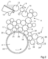
- Each printing unit also contains 2 Inking unit 6 and a dampening unit 7, which are shown in simplified form in FIG. 1.
- the printing press 1 is supported by a central electronic control device 8 controlled by a microprocessor 9. The operator can control the processes check and influence the control panel 10.
- the control device 8 controls the Printing units 2 and in particular the on and off movements of the cylinders 3, 4, 5 to each other as well as the inking unit 6 and the dampening unit 7 of each printing unit 2.
- the printing ink is stored in a color reservoir consisting of the ink fountain 11 and the ink fountain roller 12.
- the ink fountain 11 is equipped with a dosing device 13 for zonal printing ink dosing, which consists of zone-wide adjusting elements lined up closely next to one another parallel to the ink fountain roller axis.
- the reciprocating siphoning roller 14 transfers the printing ink, which has a profile with different ink layer thicknesses in the individual zonal metering areas transversely to the printing direction, from the ink fountain roller 13 to the first inking roller 15.
- the inking unit 6 also comprises a second, third and fourth driven friction roller 16 , 17, 18, a first inking roller 19, as seen in the direction of rotation of the printing form cylinder 3, and further inking rollers 20, 21, 22 for applying the printing ink to the printing plate 23.
- the dampening unit 7 comprises a basin-shaped fountain solution reservoir 24, into which the immersion roller 25 is partially immersed. At the latter, the metering roller 26 is employed under contact. The dipping roller 25 and the metering roller 26 can be driven at a variable speed, so that in this way the dampening solution flow rate, for. B.
- the dampening solution flow rate per machine revolution is changeable, so that the inking unit 6 can be supplied with a dampening solution quantity increased compared to the printing operation within a short time during the pre-moistening.
- the speed of the rollers 25, 26 can be carried along with the printing press speed as a function of this, thus ensuring a constant minimum dampening at every press speed.
- the dampening roller 27 rotating at the printing form cylinder speed and the slower rotating metering roller 26 are brought into contact with one another to form a gap with slip.
- a dampening roller 28 is placed on the dampening roller 27.
- the intermediate roller 29 can optionally be adjusted to the inking roller 19 and / or the dampening roller 27.
- the inking unit 6 and the dampening unit 7 can be in mode integrated dampening ", with the inking roller 19 and the dampening roller 27 attached to the printing form 23 and connected by the intermediate roller 29.
- the inking roller 19 applies an ink / fountain solution emulsion.
- the intermediate roller 29 is separated from at least one of the application rollers 19, 27.
- the inking unit 6 and dampening unit 7 are connected to one another by at least one roller, for example the intermediate roller 29, the inking unit 6 can be pre-moistened, the inking rollers being used 19 - 22 are switched off from the printing form 23.
- the dampening roller 27 can be set off from the printing form or, in particular when the printing starts soon, can be placed against the printing form of the inking unit 6 without a roller connecting it to the dampening unit 7 via the printing form 23.
- the automatic control 8 shown in FIG. 1 controls when starting up and after a machine stop the precise execution of all functions and stops the desired amount of dampening solution for each during printing Speed exactly one.
- the inking unit 6 and the printing form 23 are programmed pre-moistened.
- the control device 8 controls roller position, in particular the turning on and off of the inking rollers 15-18, and Dampening solution dosing in every phase.
- everyone can Ink and dampening rollers 19 - 22, 27 can be switched off from the printing form 23.
- the automatic control releases all the necessary functions automatically, that is the pre-moistening of the printing form 23 and the inking unit 6 About the intermediate roller 29 with the dampening roller 27 and the Production printing with speed-compensated dampening.
- Multi-color printing press 1 runs the one controlled by the control device 8 Automatic of the individual printing units at exactly the right time one after the other so that each dampening unit starts under optimal conditions.
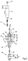
- a device is shown with which the stroke amplitude of Rubbing rollers z. B. the dampening roller 28 shown in Figure 2 and / or one or can change several of the inking rollers 15-18 simultaneously.
- the shown Example refers to the first in the ink roller relative to the ink flow Ink roller 15, the frame 29, z. B. in the side walls of the printing press, is rotatably mounted.
- the journal 30 carries the driver 31, which one Transfer of the lifting movement to the rotating inking roller 15 enables.
- the here cuboid sliding block 32 is on the sliding block joint 34 in the Rod 33 rotatably supported and connected to the driver 31 by the latter.
- the friction stroke drive 35 generates an oscillating drive movement with the amplitude H.
- This drive movement is transmitted through the rod 36 to the backdrop 37, which is rotatably mounted in the rod 36 via the link joint 38.
- the Link joint 38 is introduced into the bottom of the groove 40.
- the backdrop 37 is through the actuator 39 from the first position (shown in full line) to the second position (shown in broken lines) and adjustable back.
- the adjustment of the backdrop 37 relative to the sliding block 32 takes place in the movement phase in which the Link stone joint 34 and the link joint 38 congruent or in alignment stand on top of each other by setting 37 and setting block 38 simultaneously and be rotated together by an angle of 90 °.
- the size of the stroke amplitude of the inking roller 15 is in the first position adjusted backdrop 37 different to the stroke amplitude in the second position.
- Each after the dimensional training of scenery 37 and scenery stone 32 results in In the longitudinal direction and in the width direction of the groove 40, a freewheel of different sizes the difference A - C or B - D of the sliding block 32 in the groove 40 and to the backdrop 37.
- the sliding block 32 is carried along through the backdrop 37 in both directions. If the game A - C or B - D bigger or is the same size, no take-along.
- To change the stroke amplitude of the Inking roller 15 must assume the constant drive amplitude H Difference A - C not equal to the difference B - D.
- the game A - C of z. B. 18 mm assumption slightly, e.g. B. by 2 mm, smaller than twice the amplitude 2 H of z. B. 20 mm the drive movement, so that the stroke amplitude E of the inking roller 15 in both Directions of movement per 1 mm (minimum stroke) is when the link 37 is the first Holds position.
- the smooth sliding of the sliding block 32 in Longitudinal play B - D perpendicular to the longitudinal direction is essential less than twice the amplitude 2 H and can with z. B.
- the sliding block 32 can also here in the embodiment shown in the following figures, cylindrical be trained.
- C and D correspond to the diameter of the Setting stone and to change the stroke amplitude, A must not be equal to B.
- the the groove 40 in the longitudinal direction delimiting inner surfaces can in this case be semicircular, so that a full surface meeting of The sliding block 32 and the inner surface of the sliding block take place and wear in the form of a knocked out groove 40 is avoided.
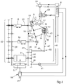
- FIG. 4 shows a preferred embodiment of the device according to the invention shown.
- the inking rollers 15 and 16 shown in Fig. 2 are here axially moved in opposite directions to each other. It can be provided that beyond that further friction rollers are actuated by the device, e.g. B. in Fig. 2nd shown inking rollers 17, 18 and the dampening roller 28.
- the device e.g. B. in Fig. 2nd shown inking rollers 17, 18 and the dampening roller 28.
- For the axial Drive and a change in the stroke amplitude of these additional friction rollers can one of the inking rollers 15; 16 with one or more of the other friction rollers be connected in terms of drive via a rocker of known type (DE 36 29 825).
- the friction rollers 15, 16 are coupled by the drive 41 via the gear 42 to the rotation of the cylinder 3 of the printing unit rotatively and via the Friction gear 43 driven axially.
- the Friction lifting gear 43 includes the gears 44-46.
- the one that functions as a crank Gear 44 forms together with the rod 47 functioning as a crank rod Crank gear 44, 47.
- the gear 44 has an eccentric to the axis 48 on this arranged crank pin 49, which via the joint 50 with the Rod 47 is connected.
- the rod 47 is formed with the bolt here Sliding block 32 connected. As shown, this can be in the sliding block joint 34 the rod 47 is rotatably mounted or non-rotatably attached to the rod 47.
- the Joint 50 and the sliding block joint 34 are each about two axes movable joints trained. As joints are z. B. spherical shells - or Universal joints can be used.
- the formation of the joints 34, 50 is preferred as Spherical roller bearings or ball bearings, with each self-aligning bearing on one eye End of the rod 47 is added.
- the inner ring center axis of the self-aligning bearing of the joint 50 runs in the image plane and corresponds to the axis of the Crank pin 49 on which the inner ring sits.
- the inner ring central axis of the Self-aligning bearing of the joint 34 runs perpendicular to the image plane and corresponds to the Axis of the sliding block 32 on which the latter inner ring sits.
- the disc-shaped backdrop 37 has a circular arc-shaped slot formed groove 40.
- the link 37 is in the lever arm 51 of the lever 52 rotatably mounted.
- the lever 52 has two further lever arms, each of which the drivers 31 are connected to one of the friction rollers 15, 16.
- the well known Type (DE 36 29 825) trained driver 31 each include a driver roller 53, between two disks attached to the journal 30 or in one Circumferential groove 54 of the journal 30 is guided.
- the lever 52 is rotatable in the frame 29 mounted, the bracket 55 the lever 52 and the lever axis 56th forming joint carries.
- the actuator is arranged on the lever 52 and is supported on an outer lever arm of the three-armed lever 52 and that on the middle Lever arm arranged backdrop 37 from.
- the actuator 39 shown is as a preferably designed in two directions pneumatic cylinder. Of the Actuator 39 is dependent on the electronic control device 8 Operating parameters of the printing press controlled. Such a thing Operating parameters can e.g. B. a certain number of revolutions of the Printing form cylinder 3.
- the control device 8 controls both the drive 41 the printing press or the printing unit and the actuator 39. Furthermore the control device 8 can switch the inking roller 57 on and off control the dampening roller not shown in Figure 4.
- the controls Control device 8 that turns the application roller 57 on and off Applicator roller actuator 58. It can also be provided that the Drive 58 not only the applicator roller 57, but also the backdrop 37 instead of additional actuator 39 actuated. Furthermore, FIG.
- valve 60 is an example for everyone mentioned pneumatic cylinder shown that this from a compressed air source 59 a valve 60 can be supplied with compressed air. Hydraulic can also be used Systems are used.
- the valve 60 shown is a multi-way valve trained and is controlled by the control device 8, for. B. magnetic operated. Via the valve 60, the piston rod 61 of the double-acting Pneumatic cylinders can optionally be extended and retracted.
- the piston rod 61 is connected via a joint 62 to the backdrop 37, so that this through the Actuator 39 can be rotated around the link joint 34. The angle of twist can be limited by additional stops.
- the rod 47 carries an oscillating thrust and Pull movement from which on the sliding block 32 engaging in the groove 40 the backdrop 37 is transmitted.
- this friction stroke drive movement with a lower idling of the sliding block 32 in the backdrop 37 than in a to the first position in substantially vertical second position not shown (without entrainment) on the Link 37 and the lever 52 transferred.
- the lever 52 is carried over a larger one Swivel angle away.
- the oscillating friction rollers 15, 16 lead z. B. pro two revolutions of the printing form cylinder 3 a full oscillation back and forth a stroke from or per revolution from the center position to a dead center position and back.
- the lever 52 thus forms the first gear member and the rod 47 the second Transmission member of the friction-type transmission 43, the link 37 relative to the lever 52 is adjustable and in particular rotatable. Both the lever 52 and the Rod 47 are driven by the drive 41.
- the lever 52 thereby leads an oscillating pivoting movement about its lever axis 56 and shifts the rotating friction rollers 15, 16 simultaneously in opposite axial directions Directions.
- One of two dead center positions of the system is shown in the figure. After a rotation of the link 37 by an angle of 90 ° in the second Position of the sliding block 32 has a greater idle, so that the backdrop 37 and the lever 52 not at all or back over a smaller swivel angle be moved. Both of the latter cases correspond to the minimum stroke.
- Fig. 5 is the rotatable about the lever axis 56 and the first gear member forming lever 52 shown in more detail.
- the backdrop 37 is the lever arm 51st worn and is rotatable about the link axis 64 in the lever arm 51 in the Bore 61 stored.
- the sliding block 32 has a circular cross section and the groove 40 is in the form of a circular arc and is in the form of an elongated hole.
- the Inner surfaces 62, 63 are concentric to the second position Lever axis 56.
- the mean radius 65 of the groove 40 corresponds to the distance between lever axis 56 and link axis 64.
- the arc length 66 of the middle The radius corresponds to the groove length A of the straight line shown in FIG. 3 extending groove 40.
- the groove 40 is arranged centrally to the link axis 64. Furthermore, the sliding block 32 is in the two dead center positions oscillating drive movement shown in dash-dotted lines. It can be seen that the Sliding block 32 in its movement over the groove length, for. B. in the case of here circular arc-shaped groove 40 shown by the pivot angle 68 each included arc length runs out. In this way, a minimum stroke of Rubbing rollers 15, 16 of z. B. 1 mm. With a longer groove 40 or A drive movement over a shorter distance can cause the swivel angle 68 be zero (striking without a middle name) or the sliding block 32 strikes not at all on the groove inner surfaces lying in its direction of movement.
- Fig. 5 is the first position of the backdrop 37 by the corresponding position of the Groove 40 (shown in dash-dotted lines) indicated. In this position there is a Taking the backdrop 37 through the sliding block 32 over a larger path, see above that an increased stroke amplitude of the friction roller compared to the minimum stroke is effected.
- FIG. 6 shows a preferred embodiment of the groove 40.
- the modification compared to the design shown in Fig. 5 consists in a along the Radius 65 belonging arc about the lever axis 56 displaced position of the Groove 40 so that the lying in the direction of movement of the sliding block 32 rounded inner surface 71 of the groove 40 extends coaxially to the link axis 64.
- On this can be a particularly quick and safe changeover of the Stroke amplitude can be realized, which is preferably in that shown in Fig. 4
- Fig. 7 is a preferred embodiment of the bearing of the lever 52, the Setting stone 32 and the backdrop 37 shown in a side view.
- the Sliding block 32 is designed as a bolt, which in the rod 47 and in at least one further lever 69 is mounted.
- Storage and in particular the storage in two further levers 69 serves to stabilize the bearing Sliding block 32 and minimizes the wear of the groove 40 by a Tilting movement of the sliding block 32 in the groove 40 due to the driving force is prevented. In this way, the game between groove 40 and Make the sliding block 32 sufficiently large so that it runs particularly smoothly Adjustment of the backdrop 37 is possible.
- the storage of the sliding block 32 in the here the second gear member of the friction-lifting gear rod 47 can advantageously take place by means of a spherical roller bearing 70.
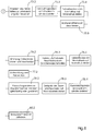
- FIG. 8 shows a program flow chart with program stages 73 to 81 to be processed by the electronic control device 8 for controlling the operation of the rotary printing press 1 according to the inventive method.
- the lifting roller is activated in parallel to supply ink to the inking unit 78.1, a setting of the inking rollers on the printing form cylinder 78.2, which can take place simultaneously or in a staggered manner, a setting of the speed of the metering and immersion roller to normal operation 78.3 and a setting of the rubber blanket cylinder on the printing form cylinder 78.4 according to program level 79, e.g. B. within several machine revolutions.
- program stage 80 the blanket cylinder is placed against the impression cylinder 80.1 and the printing material transport is reactivated 80.2, so that a printing status according to program stage 81 is now reached.
Landscapes
- Inking, Control Or Cleaning Of Printing Machines (AREA)
- Rotary Presses (AREA)
Abstract
Description
Die Erfindung betrifft ein Verfahren zum Betrieb einer Rotationsdruckmaschine nach
dem Oberbegriff von Anspruch 1 und eine Vorrichtung - insbesondere zur
Durchführung des Verfahrens - in einer Rotationsdruckmaschine nach dem
Oberbegriff von Anspruch 11.The invention relates to a method for operating a rotary printing press
the preamble of
Das erfindungsgemäße Verfahren betreffend sind Betriebsverfahren bekannt, welche vorsehen, daß bei Betriebsunterbrechungen das Druckwerk ohne Bedruckstofftransport und das Farbwerk ohne Farbzufuhr und -abnahme weiterläuft. Die seitliche Verreibung wird verringert, damit in diesem Betriebszustand das sich zonal unterscheidende Farbschichtdickenprofil im Farbwerk erhalten bleibt. Vor Wiederaufnahme des Druckbetriebes erfolgt eine Vorfeuchtung des Farbwerkes. Die Vorfeuchtung ist erforderlich, um das durch die Feuchtmittelverdunstung während der Unterbrechung gestörte Farbe/Feuchtmittel -Gleichgewicht im Farbwerk und auf der Druckform unverzüglich auf einen für den Fortdruck günstigen Wert einzustellen, so daß Makulatur vermieden wird.Operating methods are known which relate to the method according to the invention provide that the printing unit without Printing material transport and the inking unit continues without ink supply and removal. The lateral rubbing is reduced so that in this operating state zone-differentiating ink layer thickness profile is retained in the inking unit. In front The inking unit is pre-moistened before printing is resumed. The Pre-humidification is required to do this through the dampening solution evaporation the interruption of the ink / fountain solution balance in the inking unit and on immediately set the printing form to a value that is favorable for the production run, so that waste is avoided.
In der EP 0 545 237 B1 ist ein Farbwerk beschrieben, bei welchem eine
Wiederaufnahme der Changierbewegung der Reiberwalzen zeitgleich mit dem
Anstellen der Farbauftragswalzen an die Druckform erfolgt. Dies kann über eine
schaltungstechnische Verknüpfung des ![]()
![]()
In der EP 0 705 692 A1 sind ein Verfahren und eine Vorrichtung zum Umstellen eines Farbwerkes beschrieben, welche die genannten Unzulänglichkeiten des Standes der Technik nicht beseitigen.EP 0 705 692 A1 describes a method and a device for changing over described an inking system, which the aforementioned shortcomings of Do not eliminate the state of the art.
Die erfindungsgemäße Vorrichtung betreffend ist bekannt, daß zur Veränderung der Hubgröße der seitlichen Verreibung Vorrichtungen eingesetzt werden, mit denen der Hub einer rotierenden Reibwalze bei laufendem Farbwerk erhöht und verringert werden kann.The device according to the invention is known to change the Stroke size of the lateral trituration devices are used with which the Stroke of a rotating friction roller increased and decreased with the inking unit running can be.
In der DE 36 29 825 A1 ist eine Einrichtung zum axialen Verstellen der Reibwalzen beschrieben, mit welcher sich die axiale Bewegung der Reibwalzen von 0 bis zu einem Maximum regulieren läßt und die ein Reguliersegment mit einer Antriebsnut umfaßt. Das Reguliersegment ist auf einer Achse verdrehbar in einer Seitenwand gelagert. Eine derart ausgebildete Einrichtung ist zwar im Vergleich zu der im erstgenannten Dokument des Standes der Technik beschriebenen Vorrichtung fertigungstechnisch unaufwendiger und weniger störanfällig, da kein phasenrichtiges Einrasten von Kupplungsteilen konstruktiv berücksichtigt werden muß, beansprucht jedoch viel Bauraum. Zudem ist ein schlagartiger Wechsel zwischen einem Minimalhub und einem Maximalhub nicht möglich, da die Verdrehung und die Arretierung des Reguliersegmentes mit Hilfe der Zahnräder immer noch relativ lange dauert.DE 36 29 825 A1 describes a device for axially adjusting the friction rollers with which the axial movement of the friction rollers from 0 to a maximum and a regulation segment with a drive groove includes. The regulating segment can be rotated on an axis in a side wall stored. Such a device is compared to that in first-mentioned document of the prior art device described production-technically less complex and less prone to faults, since no phase is correct Snap engagement of coupling parts must be considered constructively, claimed however, a lot of space. There is also a sudden change between one Minimum stroke and a maximum stroke not possible because the twist and the Locking of the regulating segment with the help of the gears is still relatively long lasts.
In der DE 25 07 179 C2 ist eine Antriebseinrichtung für changierende Reibwalzen beschrieben, welche die Unzulänglichkeiten des zuletzt beschriebenen Standes der Technik nicht beseitigt. DE 25 07 179 C2 describes a drive device for oscillating friction rollers described the shortcomings of the last described state of the Technology not eliminated.
Der Erfindung liegt die Aufgabe zugrunde, die beim Betrieb einer Rotationsdruckmaschine infolge kurzzeitiger Unterbrechungen anfallende Makulatur zu minimieren.The invention has for its object in the operation of a Rotary printing machine waste due to brief interruptions to minimize.
Die Aufgabe wird durch ein Verfahren mit den Merkmalen von Anspruch 1 und durch
eine Vorrichtung mit den Merkmalen von Anspruch 11gelöst.The object is achieved by a method having the features of
Das erfindungsgemäße Verfahren zum Betrieb einer ein Farbwerk umfassenden
Rotationsdruckmaschine, wobei das Farbwerk mindestens eine mit veränderbarer
Hubamplitude axial oszillierende Farbreibwalze umfaßt, zeichnet sich dadurch aus,
daß die Rotationsdruckmaschine zuerst in einem Betriebsmodus
Die Erfindung geht von der Beobachtung aus, daß beim Betrieb einer
Druckmaschine in der dem Stand der Technik entsprechenden Art und Weise die für
eine Wiederherstellung des Fortdruckzustandes notwendigen und nach
Wiederaufnahme des Druckbetriebes erfolgenden Anpaß- und Ausgleichvorgänge
im Farbwerk einen relativ hohen Makulaturanfall bedingen. Erfindungsgemäß wurde
erkannt, daß sich Makulatur minimieren läßt, wenn die Ausgleichvorgänge während
der Druckunterbrechung und insbesondere vor dem Aufsetzen der
Farbauftragswalze oder -walzen auf die Druckform für deren Einfärbung stattfinden.
Durch ein Wiedereinsetzen der seitlichen Verreibung noch vor dem einen Stopper
folgenden erneutem Druckbeginn wird unter Ausnutzung der Thixotropie der
Druckfarbe eine für die Einfärbung der Druckform optimale Verflüssigung der
Druckfarbe erreicht. Der Druckbeginn erfolgt, wenn wieder Bedruckstoff durch das
Druckwerk transportiert und in diesem bedruckt wird, z. B. mit dem in eine
elektronische Steuereinrichtung eingegebenen Befehl
Die Hubamplitude der Reibwalze kann im ersten Betriebsmodus von einem
stillgesetzten Axialhub oder einem sehr kleinen Hub, z. B. 1 mm, ausgehend
vergrößert werden. Die Hubamplitude kann auf dem Normalhub, welcher eine
günstige seitliche Verreibung während des Druckbetriebes gewährleistet, oder auf
eine relativ zur Normalhubamplitude unterschiedliche, d. h. größere oder kleinere,
Hubamplitude vergrößert werden. Nach der Vergrößerung der Hubamplitude im
ersten Betriebsmodus kann unter fortwährender Beibehaltung dieser Hubamplitude
ein Übergang in den zweiten Betriebsmodus erfolgen. Nach einer zwischenzeitlichen
Vergrößerung kann aber auch wieder eine Verringerung der Hubamplitude, z. B. auf
den Minimalhub, erfolgen, wobei mit dem Befehl
Vorzugsweise kann der Befehl
Bei einer besonders vorteilhaften Ausgestaltung des erfindungsgemäßen Verfahrens kann vorgesehen sein, daß während des ersten Betriebsmodus eine Vorfeuchtung des Farbwerkes erfolgt. Dem Farbwerk kann das Feuchtmittel zur Vorfeuchtung durch eine Feuchtmittelzufuhreinrichtung, z. B. ein an der Druckmaschine ohnehin vorhandenes Feuchtwerk mit Walzen zugeführt werden.In a particularly advantageous embodiment of the method according to the invention it can be provided that during the first operating mode a pre-moistening the inking takes place. The dampening solution can be used for pre-moistening the inking unit by a dampening solution supply device, e.g. B. on the printing press anyway Existing dampening system can be fed with rollers.
In Untersuchungen zeigte sich, daß bei einer vergleichsweise kurzen Vorfeuchtdauer mit erhöhter Hubamplitude, z. B. während drei bis fünf Maschinenumdrehungen, ein Abbau der zonalen Farbdosierung in wesentlichen vermieden werden kann. Das Farbwerk kann je nach Druckmaschinentyp unterschiedlich ausgebildet sein, wobei der Abstand der Farbreibwalze mit veränderbarer Hubamplitude zur dieser das Feuchtmittel zuführenden Feuchtmittelzuführeinrichtung je nach Maschinentyp z. B. aufgrund unterschiedlicher Anzahlen zwischengeordneter Farbwerkswalzen unterschiedlich groß sein kann. Dementsprechend unterschiedlich kann die Zeitdauer (Reaktionszeit) sein, bis das zugeführte Feuchtmittel über den Farbwalzenzug bis zur Farbreibwalze fließt, bzw. gefördert wird. Je nach Trägheit des Systems kann das vorfeuchtende Feuchtmittel dem Farbwerk vor, nach oder vorzugsweise zeitgleich mit der Vergrößerung der Hubamplitude zugeführt werden. Wesentlich bei dieser vorteilhaften Ausbildung der Erfindung ist, daß dem Farbwerk Feuchtmittel zugeführt wird, während die Farbreibwalze mit einer gegenüber dem Minimalhub erhöhten Hubamplitude oszilliert.Studies have shown that with a comparatively short pre-wetting time with increased stroke amplitude, e.g. B. during three to five machine revolutions Degradation of the zonal color dosage can be substantially avoided. The Inking unit can be designed differently depending on the type of printing press, whereby the distance of the inking roller with variable stroke amplitude to this Depending on the machine type z. B. due to different numbers of intermediate inking rollers can be of different sizes. The can vary accordingly Period of time (reaction time) until the dampening solution supplied over the Ink roller train flows to the inking roller, or is conveyed. Depending on the inertia of the system, the pre-dampening dampening solution can be used before, after or are preferably supplied simultaneously with the increase in the stroke amplitude. It is essential in this advantageous embodiment of the invention that the inking unit Dampening solution is supplied while the inking roller with an opposite Minimal stroke increased stroke amplitude oscillates.
Vorzugsweise kann ein mit veränderbarer Feuchtmittelfördermenge betreibbares Feuchtwerk eingesetzt werden, wobei dieses bei der Vorfeuchtung mit gegenüber dem Normalbetrieb erhöhter Förderleistung arbeitet. Dazu kann bei einem Heberfeuchtwerk der Hebertakt und bei einem Filmfeuchtwerk die Rotationsgeschwindigkeit der Walzen, z. B. einer Tauchwalze und einer Dosierwalze, erhöht werden. Die Zeitdauer der Vorfeuchtung und der seitlichen Verreibung mit vergrößerter Hubamplitude kann auf eine bestimmte Anzahl Umdrehungen der Druckwerkszylinder (Maschinenumdrehungen) bezogen und in Abhängigkeit von weiteren Betriebsparametern der Druckmaschine gesteuert sowie variabel vorwählbar sein.Preferably, one that can be operated with a variable fountain solution delivery rate Dampening can be used, with this in the pre-moistening opposite the normal operation of increased output works. This can be done with a Lifter dampening the lifter cycle and for a film dampening the Rotation speed of the rollers, e.g. B. a plunger and one Dosing roller, can be increased. The length of time for pre-wetting and side wetting Rubbing with increased stroke amplitude can be limited to a certain number Revolutions of the printing unit cylinders (machine revolutions) related and in Depending on other operating parameters of the printing press controlled as well be variably preselectable.
Bei Flachdruckrotationsdruckmaschinen mit einem Farbwerk und einem Feuchtwerk kann eine Vorfeuchtung über zumindest eine das Farbwerk mit dem Feuchtwerk zumindest zeitweise verbindende Walze erfolgen, über welche das Feuchtmittel vom Feuchtwerk ins Farbwerk, z. B. direkt auf eine Farbauftragswalze, gefördert wird. Die Vorfeuchtung des Farbwerkes kann gleichzeitig mit einer Vorfeuchtung der Druckform, z. B. bei einer an die Druckform angestellten Feuchtauftragswalze und von der Druckform abgestellten Farbauftragswalzen, erfolgen. Diese Variante ist vorteilhaft, wenn unmittelbar auf die Vorfeuchtung folgend der Druckbetrieb wieder aufgenommen wird. Die Vorfeuchtung kann aber auch bei von der Druckform abgestellten Farbauftragswalzen und ebenfalls abgestellter Feuchtauftragswalze erfolgen. Diese Variante ist bei zur Vorfeuchtung verzögertem Druckbeginn vorteilhaft.For planographic printing presses with an inking unit and a dampening unit can be pre-moistened by at least one of the inking units with the dampening unit at least temporarily connecting roller take place over which the dampening solution from Dampening unit in the inking unit, e.g. B. is promoted directly to an inking roller. The Pre-wetting of the inking unit can be carried out at the same time as pre-wetting the Printing form, e.g. B. with a dampening roller applied to the printing form and ink application rollers parked by the printing form. This variant is advantageous if the printing operation starts again immediately after the pre-moistening is recorded. Pre-moistening can also take place from the printing form parked inking rollers and also dampening roller respectively. This variant is when the start of printing is delayed for pre-moistening advantageous.
Untersuchungen ergaben, daß bei einer Vorfeuchtung in der bisher üblichen Art und Weise, d. h. bei unveränderter Beibehaltung des Minimalhubes, bei Druckbeginn schlierenartige Flecke in den Rasterflächen auftraten. Diese Flecke führen zu einer zusätzlichen Erhöhung der Makulaturmenge. Als Ursache wurde festgestellt, daß bei einer konventionellen Vorfeuchtung mit minimaler seitlicher Farbverreibung das verstärkt zugeführte und teilweise einen Oberflächenwasserfilm bildende Feuchtmittel zu wenig geglättet wird, bevor es auf die Druckform und die darauf befindliche Druckfarbe aufgetragen wird. Erfindungsgemäß wurde erkannt, daß diese Druckschwierigkeiten vermieden werden können, wenn das zur Vorfeuchtung dem Farbwerk während der Druckunterbrechung zugeführte Feuchtmittel mit gegenüber dem Minimalhub erhöhter Hubamplitude, z. B. mit voller seitlicher Verreibung (Normalhub), zusammen mit der Farbe verrieben wird. Dadurch emulgiert ein größerer Anteil des Feuchtmittels in die Farbe und der verbleibende Oberflächenwasserfilm auf den Farbwalzen wird zudem geglättet. Studies have shown that pre-wetting in the usual way and Way, d. H. with unchanged retention of the minimum stroke, at the start of printing streak-like spots appeared in the grid areas. These spots lead to one additional increase in the amount of waste. The cause was found to be a conventional pre-moistening with minimal lateral rubbing increasingly supplied and partially forming a surface water film Too little dampening solution is smoothed before it is applied to the printing form and on it printing ink is applied. According to the invention, it was recognized that these pressure problems can be avoided if that is for pre-wetting dampening solution supplied to the inking unit during printing interruption compared to the minimum stroke increased stroke amplitude, e.g. B. with full side Rubbing (normal stroke) is rubbed together with the color. Thereby a larger proportion of the dampening solution emulsifies into the ink and the remaining one Surface water film on the ink rollers is also smoothed.
Das Druckwerk, das Farbwerk und das Feuchtwerk können in Abstimmung zueinander von einer elektronischen Steuereinrichtung gesteuert werden. Diese kann die An- und Abstellbewegungen der Druckwerkszylinder und die An- und Abstellbewegungen der Farbauftragswalzen und der Feuchtauftragswalze an und von dem Druckformzylinder steuern.The printing unit, the inking unit and the dampening unit can be coordinated can be controlled to each other by an electronic control device. This can the on and off movements of the printing unit cylinder and the on and Parking movements of the inking rollers and the dampening roller on and control from the printing form cylinder.
Bei einer besonders vorteilhaften Ausgestaltung des erfindungsgemäßen Verfahrens kann vorgesehen sein, daß die das Druckwerk, das Farbwerk und das Feuchtwerk steuernde elektronische Steuereinrichtung auch die erfindungsgemäße Vorrichtung zur Veränderung der Hubamplitude und insbesondere deren Stellantrieb steuert.In a particularly advantageous embodiment of the method according to the invention can be provided that the printing unit, the inking unit and the dampening unit Controlling electronic control device also the device according to the invention controls to change the stroke amplitude and in particular their actuator.
Die erfindungsgemäße Vorrichtung - insbesondere zur Durchführung des erfindungsgemäßen Verfahrens - zur Veränderung der Hubamplitude mindestens einer axial oszillierenden Reibwalze in einem Auftragswerk - insbesondere im Farbwerk - einer Rotationsdruckmaschine, wobei die Reibwalze durch einen Reiberhubantrieb über ein Reiberhubgetriebe antreibbar ist, welches eine von einer ersten Stellung in eine zweite Stellung verstellbare Kulisse mit einer Nut und einen in der Nut bewegbaren Kulissenstein umfaßt, zeichnet sich dadurch aus, daß die Kulisse von einem ersten Getriebeglied und der Kulissenstein von einem zweiten Getriebeglied des Reiberhubgetriebes getragen wird, daß die Kulisse verstellbar relativ zum ersten Getriebeglied angeordnet ist, und daß beide Getriebeglieder durch den Reiberhubantrieb antreibbar sind.The device according to the invention - in particular for carrying out the inventive method - to change the stroke amplitude at least an axially oscillating friction roller in a job - especially in Inking unit - a rotary printing machine, the friction roller through a The friction stroke drive can be driven via a friction stroke transmission, which is one of one first position in a second position adjustable backdrop with a groove and one in the groove movable sliding block, is characterized in that the Backdrop of a first gear link and the backdrop block of a second Gear member of the friction lifting gear is worn that the backdrop is adjustable is arranged relative to the first gear member, and that both gear members by the friction stroke drive can be driven.
Mit dieser Vorrichtung ist das erfindungsgemäße Verfahren besonders günstig durchführbar, da die Vorrichtung eine sehr schnelle Veränderung der Hubamplitude der Reibwalze bei geringen, vom Stellantrieb zur Verstellung aufzubringenden Stellkräften, ermöglicht. Im Gegensatz zu im Stand der Technik beschriebenen Vorrichtungen, bei denen die Kulissenführung in einem Fall als Einstellglied eines Koppelgetriebes und im anderen Fall als Führungskurve eines Schubkurbelgetriebes eingesetzt wird, fungiert die Kulissenführung erfindungsgemäß als ein wahlweise, insbesondere von einer ersten in eine zweite Position und von der zweiten in die erste Position, verstellbarer Mitnehmer. Durch die Kombination von der Kulisse mit dem Kulissenstein kann eine oszillierende Antriebsbewegung - je nachdem ob die Kulisse oder das den Kulissenstein tragende Getriebeglied das antreibende oder das angetriebene Getriebeglied ist - vom ersten Getriebeglied auf das zweite Getriebeglied oder vom zweiten Getriebeglied auf das erste Getriebeglied übertragen werden. Durch die Anordnung der Kulisse an einem ersten bewegbaren Getriebeglied und des Kulissensteines an einem zweiten bewegbaren Getriebeglied des Reiberhubgetriebes und die Verstellbarkeit der Kulisse gegenüber dem diese tragenden Getriebeglied kann durch einen, insbesondere hinsichtlich des Gestänges, vereinfachten Aufbau des Reiberhubgetriebes der Bauraum besser ausgenutzt und der Fertigungsaufwand gesenkt werden.With this device, the method according to the invention is particularly favorable feasible because the device changes the stroke amplitude very quickly the friction roller at low, to be applied by the actuator for adjustment Actuators, enables. In contrast to those described in the prior art Devices in which the link guide in one case as an adjusting one Coupling gear and in the other case as a guide curve of a sliding crank gear is used, the backdrop guide acts according to the invention as an optional, in particular from a first to a second position and from the second to the first position, adjustable carrier. By combining the backdrop with the sliding block can an oscillating drive movement - depending after whether the backdrop or the link that carries the sliding block the driving or the driven gear link is - from the first gear link the second gear link or from the second gear link to the first gear link be transmitted. By arranging the backdrop on a first movable Gear link and the sliding block on a second movable gear link of the friction lifting gear and the adjustability of the setting compared to this load-bearing gear member can by a, especially with regard to Linkage, simplified construction of the friction lifting gear the installation space better exploited and the manufacturing costs can be reduced.
Unter einer Nut soll nachfolgend sowohl eine Nut mit Bodenfläche (Grund) als auch ein Langloch ohne Bodenfläche und unter einem Kulissenstein sowohl ein Gleitstein als auch eine Rolle verstanden werden. Der Kulissenstein kann einen kreisförmigen (z. B. Bolzen) oder polygonförmigen (z. B. Vierkant) Querschnitt aufweisen.Below a groove, a groove with a bottom surface (bottom) as well as an elongated hole without floor space and under a sliding block both a sliding block be understood as a role as well. The sliding block can be circular (e.g. bolt) or polygonal (e.g. square) cross section.
Bei einer besonders vorteilhaften Ausbildung der erfindungsgemäßen Vorrichtung kann vorgesehen sein, daß die Kulisse durch einen Stellantrieb von der ersten in die zweite Stellung verstellbar ist, wobei der Stellantrieb durch eine elektronische Steuereinrichtung, insbesondere nach dem erfindungsgemäßen Verfahren, gesteuert werden kann. Als Stellantrieb können z. B. elektromagnetische Aktuatoren sowie pneumatische und hydraulische Kolben-Zylinder-Einheiten verwendet werden. Die Verwendung eines doppeltwirkenden bzw. in beide Richtungen beaufschlagbaren Pneumatikzylinders ist vorteilhaft, da die Kulisse mit diesem sehr sicher in den entsprechenden Positionen gehalten werden kann. Das erfindungsgemäße Verfahren und die Vorrichtung sind in Bogen- und Rollenrotationsdruckmaschinen einsetzbar. In a particularly advantageous embodiment of the device according to the invention can be provided that the backdrop of an actuator from the first in the second position is adjustable, the actuator being electronic Control device, in particular controlled by the method according to the invention can be. As an actuator z. B. electromagnetic actuators as well pneumatic and hydraulic piston-cylinder units are used. The Use of a double-acting or actable in both directions Pneumatic cylinder is advantageous because the backdrop is very secure in the corresponding positions can be held. The invention The method and the device are in sheet-fed and web-fed rotary printing machines applicable.
Weitere Merkmale der Erfindung sind in den Unteransprüchen enthalten.Further features of the invention are contained in the subclaims.
Die Erfindung wird nachfolgend mit Bezug auf die Zeichnung anhand mehrerer Ausführungsformen beschrieben.The invention is described below with reference to the drawing based on several Embodiments described.
In den Zeichnungen zeigt:
- Fig. 1
- eine schematische Darstellung einer Bogenoffsetrotationsdruckmaschine mit elektronischer Steuereinrichtung,
- Fig. 2
- eine detailliertere schematische Darstellung des Farbwerkes und des Feuchtwerks der Druckmaschine aus Fig. 1,
- Fig. 3
- eine schematisch dargestellte Vorrichtung zur Veränderung der Hubamplitude einer Reibwalze,
- Fig. 4
- eine schematische Darstellung einer bevorzugten Ausführungsform der erfindungsgemäßen Vorrichtung,
- Fig. 5
- eine detailliertere schematische Darstellung eines Hebels der Vorrichtung aus Fig. 4,
- Fig. 6
- eine schematische Darstellung einer vorteilhaften Ausbildung der Kulisse,
- Fig. 7
- eine schematische Darstellung der Lagerung des Hebels aus Fig. 5 und
- Fig. 8
- einen Programmablaufplan, nach welchem die elektronische Steuereinrichtung der Druckmaschine die erfindungsgemäße Vorrichtung zur Durchführung des erfindungsgemäßen Verfahrens ansteuert.
- Fig. 1
- 1 shows a schematic representation of a sheet-fed offset rotary printing machine with an electronic control device,
- Fig. 2
- 2 shows a more detailed schematic illustration of the inking unit and the dampening unit of the printing press from FIG. 1,
- Fig. 3
- 1 shows a schematically illustrated device for changing the stroke amplitude of a friction roller,
- Fig. 4
- 2 shows a schematic representation of a preferred embodiment of the device according to the invention,
- Fig. 5
- 4 shows a more detailed schematic illustration of a lever of the device from FIG. 4,
- Fig. 6
- a schematic representation of an advantageous embodiment of the backdrop,
- Fig. 7
- is a schematic representation of the storage of the lever of Fig. 5 and
- Fig. 8
- a program flow chart according to which the electronic control device of the printing press controls the device according to the invention for carrying out the method according to the invention.
Gleiche oder funktionsgleiche Teile sind in den Figuren in der Regel mit demselben Bezugszeichen versehen.Identical or functionally identical parts are generally the same in the figures Provide reference numerals.
In Fig. 1 ist eine Bogenrotationsdruckmaschine 1 mit mehreren Druckwerken 2
dargestellt. Jedes Druckwerk 2 umfaßt eine Flachdruckeinrichtung, welche, wie
gezeigt, aus dem Druckformzylinder 3, dem Gummituchzylinder 4 und dem
Gegendruckzylinder 5 bestehen kann. Weiterhin enthält jedes Druckwerk 2 ein
Farbwerk 6 und ein Feuchtwerk 7, welche in der Fig. 1 vereinfacht dargestellt sind.
Die Druckmaschine 1 wird durch eine zentrale elektronische Steuereinrichtung 8 mit
einem Mikroprozessor 9 gesteuert. Der Bediener kann die Steuerungsprozesse über
das Bedienpult 10 kontrollieren und beeinflussen. Die Steuereinrichtung 8 steuert die
Druckwerke 2 und insbesondere die An- und Abstellbewegungen der Zylinder 3, 4, 5
zueinander sowie das Farbwerk 6 und das Feuchtwerk 7 eines jeden Druckwerkes 2.1 shows a sheet-fed
In Fig. 2 sind das Farbwerk 6 und das Feuchtwerk 7 der Druckmaschine 1 aus der
Fig. 1detaillierter gezeigt. Die Druckfarbe ist in einem aus dem Farbkasten 11 und
der Farbkastenwalze 12 bestehenden Farbreservoir gespeichert. Der Farbkasten 11
ist mit einer Dosiereinrichtung 13 zur zonalen Druckfarbedosierung ausgestattet,
welche aus parallel zur Farbkastenwalzenachse dicht nebeneinander aufgereihten
zonenbreiten Stellelementen besteht. Die hin- und herpendelnde Heberwalze 14
überträgt die quer zur Druckrichtung ein Profil mit unterschiedlichen
Farbschichtdicken in den einzelnen zonalen Dosierbereichen aufweisende
Druckfarbe von der Farbkastenwalze 13 auf die erste Farbreibwalze 15. Neben
dieser umfaßt das Farbwerk 6 noch eine zweite, dritte und vierte angetriebene
Reibwalze 16, 17, 18, eine in Drehrichtung des Druckformzylinders 3 gesehen erste
Farbauftragswalze 19 sowie weitere Farbauftragswalzen 20, 21, 22 zum Auftragen
der Druckfarbe auf die Druckform 23. Das Feuchtwerk 7 umfaßt ein beckenförmiges
Feuchtmittelreservoir 24, in welches die Tauchwalze 25 teilweise eintaucht. An
letztere ist die Dosierwalze 26 unter Kontakt angestellt. Die Tauchwalze 25 und die
Dosierwalze 26 sind mit variabler Geschwindigkeit antreibbar, so daß auf diese
Weise die Feuchtmittelfördermenge, z. B. die Feuchtmittelfördermenge pro
Maschinenumdrehung, veränderbar ist, so daß dem Farbwerk 6 während der
Vorfeuchtung eine gegenüber dem Druckbetrieb erhöhte Feuchtmittelmenge
innerhalb kurzer Zeit zugeführt werden kann. Zudem kann die Geschwindigkeit der
Walzen 25, 26 mit der Druckmaschinengeschwindigkeit in Abhängigkeit von dieser
mitgeführt werden, wobei somit eine gleichbleibende Minimalfeuchtung bei jedem
Maschinentempo gewährleistet ist. Die mit Druckformzylindergeschwindigkeit
rotierende Feuchtauftragswalze 27 und die langsamer rotierende Dosierwalze 26
sind unter Bildung eines Spaltes mit Schlupf kontaktlos aneinander angestellt. An die
Feuchtauftragswalze 27 ist eine Feuchtreibwalze 28 angestellt. Die Zwischenwalze
29 ist wahlweise an die Farbauftragswalze 19 und /oder die Feuchtauffragswalze 27
anstellbar. Das Farbwerk 6 und das Feuchtwerk 7 können im Modus
Die in Fig. 1 gezeigte automatische Steuerung 8 steuert beim Anlaufen und nach
einem Maschinenstopp gezielt den präzisen Ablauf aller Funktionen und hält
während des Fortdrucks die gewünschte Feuchtmittelmenge bei jeder
Geschwindigkeit genau ein. Das Farbwerk 6 und die Druckform 23 werden
programmiert vorgefeuchtet. Die Steuereinrichtung 8 steuert Walzenstellung,
insbesondere das An- und Abstellen der Farbauftragswalzen 15 - 18, und
Feuchtmitteldosierung in jeder Phase. Bei einer Druckunterbrechung können alle
Farb- und Feuchtauftragswalzen 19 - 22, 27 von der Druckform 23 abgestellt sein.
Beim Wiederanlaufen löst die Steuerautomatik alle notwendigen Funktionen
selbsttätig aus, das sind das Vorfeuchten der Druckform 23 und des Farbwerkes 6
über die Zwischenwalze 29 bei angestellter Feuchtauftragswalze 27 sowie der
Fortdruck mit geschwindigkeitskompensierter Feuchtung. Nach dem Vorfeuchten
können dann ebenfalls automatisch die Farbauftragswalzen 15 - 18 an die
Druckform 23 zu deren Einfärbung angestellt werden. In der in Figur 1 gezeigten
Mehrfarbendruckmaschine 1 läuft die von der Steuereinrichtung 8 gesteuerte
Automatik der einzelnen Druckwerke zeitlich im genau richtigen Abstand
nacheinander ab, so daß jedes Feuchtwerk unter optimalen Bedingungen startet.The
In Fig. 3 ist eine Vorrichtung gezeigt, mit welcher sich die Hubamplitude von
Reibwalzen z. B. der in Figur 2 gezeigten Feuchtreibwalze 28 und / oder einer oder
gleichzeitig mehrerer der Farbreibwalzen 15 - 18 verändern läßt. Das gezeigte
Beispiel bezieht sich auf die im Farbwalzenzug bezogen auf den Farbfluß erste
Farbreibwalze 15, die im Gestell 29, z. B. in den Seitenwänden der Druckmaschine,
drehbar gelagert ist. Der Achszapfen 30 trägt den Mitnehmer 31, welcher eine
Übertragung der Hubbewegung auf die rotierende Farbreibwalze 15 ermöglicht. Der
hier quaderförmige Kulissenstein 32 ist über das Kulissensteingelenk 34 in der
Stange 33 drehbar gelagert und durch letzere mit dem Mitnehmer 31 verbunden. Der
Reiberhubantrieb 35 erzeugt eine oszillierende Antriebsbewegung mit der Amplitude
H. Diese Antriebsbewegung wird durch die Stange 36 auf die Kulisse 37 übertragen,
welche über das Kulissengelenk 38 in der Stange 36 drehbar gelagert ist. Das
Kulissengelenk 38 ist in den Boden der Nut 40 eingebracht. Die Kulisse 37 ist durch
den Stellantrieb 39 aus der ersten Position (vollinig dargestellt) in die zweite Position
(strichpunktiert dargestellt) und zurück verstellbar. Die Verstellung der Kulisse 37
relativ zum Kulissenstein 32 erfolgt in jener Bewegungsphase, in welcher das
Kulissensteingelenk 34 und das Kulissengelenk 38 deckungsgleich bzw. fluchtend
übereinander stehen, indem Kulisse 37 und Kulissenstein 38 gleichzeitig und
gemeinsam um einen Winkel von 90° verdreht werden.In Fig. 3 a device is shown with which the stroke amplitude of
Rubbing rollers z. B. the dampening
Die Größe der Hubamplitude der Farbreibwalze 15 ist bei einer in die erste Position
verstellten Kulisse 37 unterschiedlich zur Hubamplitude in der zweiten Position. Je
nach der maßlichen Ausbildung von Kulisse 37 und Kulissenstein 32 ergibt sich in
Längsrichtung und in Breitenrichtung der Nut 40 eine unterschiedlich großer Freilauf
der Differenz A - C bzw. B - D des Kulissensteines 32 in der Nut 40 und zur Kulisse
37. Im Fall, daß das Spiel A - C bzw. B - D kleiner als die Größe 2 H der doppelten
Amplitude der Antriebsbewegung ist, erfolgt eine Mitnahme des Kulissensteines 32
durch die Kulisse 37 in beide Richtungen. Wenn das Spiel A - C bzw. B - D größer
oder gleich groß ist erfolgt keine Mitnahme. Zur Veränderung der Hubamplitude der
Farbreibwalze 15 muß bei angenommener konstanter Antriebsamplitude H die
Differenz A - C ungleich der Differenz B - D sein.The size of the stroke amplitude of the inking
Im gezeigten Beispiel ist das Spiel A - C von z. B. 18 mm annahmeweise
geringfügig, z. B. um 2 mm, kleiner als die doppelte Amplitude 2 H von z. B. 20 mm
der Antriebsbewegung, so daß die Hubamplitute E der Farbreibwalze 15 in beiden
Bewegungsrichtungen je 1 mm (Minimalhub) beträgt, wenn die Kulisse 37 die erste
Position innehat. Das ein leichtgängiges Gleiten des Kulissensteines 32 in
Längsrichtung ermöglichende Spiel B - D senkrecht zur Längsrichtung ist wesentlich
kleiner als die doppelte Amplitude 2 H und kann mit z. B. 0,05 mm praktisch Null
sein, so daß die Hubamplitute E bei in die zweite Position gestellter Kulisse 37
größer (Normalhub) als bei in die erste Position gestellter Kulisse 37 ist und im
Beispiel 20 mm beträgt. Selbstverständlich kann auch hier der Kulissenstein 32 wie
bei der in den folgenden Figuren gezeigten Ausführungsform zylinderförmig
ausgebildet sein. In diesem Fall entsprechen C und D dem Durchmesser des
Kulissensteines und zur Veränderung der Hubamplitute muß A ungleich B sein. Die
die Nut 40 in Längsrichtung begrenzenden Innenflächen können in diesem Fall
halbkreisförmig ausgebildet sein, so daß ein vollflächiges Aufeinandertreffen von
Kulissenstein 32 und Kulisseninnenfläche erfolgt und ein Verschleiß in Form einer
ausgeschlagenen Nut 40 vermieden wird.In the example shown, the game A - C of z. B. 18 mm assumption
slightly, e.g. B. by 2 mm, smaller than twice the
In Fig. 4 ist eine bevorzugte Ausführungsform der erfindungsgemäßen Vorrichtung
dargestellt. Die in Fig. 2 gezeigten Farbreibwalzen 15 und 16 werden hier
gegensinnig zueinander axial bewegt. Es kann vorgesehen sein, daß darüber hinaus
weitere Reibwalzen durch die Vorrichtung betätigt werden, z. B. die in Fig. 2
gezeigten Farbreibwalzen 17, 18 und die Feuchtreibwalze 28. Für den axialen
Antrieb und eine Veränderung der Hubamplitude dieser weiteren Reibwalzen kann
eine der Farbreibwalzen 15; 16 mit einer oder mehreren der weiteren Reibwalzen
über eine Wippe bekannter Bauart (DE 36 29 825) antriebsmäßig verbunden sein.
Die Reibwalzen 15, 16 werden durch den Antrieb 41 über das Getriebe 42 gekoppelt
an die Rotation des Zylinders 3 des Druckwerkes rotativ und über das
Reiberhubgetriebe 43 axial angetrieben. Für den axialen und rotativen Antrieb
können auch zwei voneinander getrennte Antriebe vorgesehen sein. Das
Reiberhubgetriebe 43 umfaßt die Zahnräder 44 - 46. Das als Kurbel fungierende
Zahnrad 44 bildet zusammen mit der als Kurbelstange fungierenden Stange 47 ein
Kurbelgetriebe 44, 47. Das Zahnrad 44 weist einen zu dessen Achse 48 exzentrisch
an diesem angeordneten Kurbelzapfen 49 auf, welcher über das Gelenk 50 mit der
Stange 47 verbunden ist. Die Stange 47 ist mit dem hier als Bolzen ausgebildeten
Kulissenstein 32 verbunden. Dieser kann, wie gezeigt, in den Kulissensteingelenk 34
der Stange 47 drehbar gelagert oder drehfest an der Stange 47 befestigt sein. Das
Gelenk 50 und das Kulissensteingelenk 34 sind als um jeweils zwei Achsen
bewegliche Gelenke ausgebildet. Als Gelenke sind z. B. Kugelschalen - oder
Kreuzgelenke einsetzbar. Bevorzugt wird die Ausbildung der Gelenke 34, 50 als
Pendelrollenlager oder -kugellager, wobei jedes Pendellager von einem Auge am
Ende der Stange 47 aufgenommen wird. Die Innenringmittelachse des Pendellagers
des Gelenkes 50 verläuft in der Bildebene und entspricht der Achse des
Kurbelzapfens 49, auf dem der Innenring sitzt. Die Innenringmittelachse des
Pendellagers des Gelenkes 34 verläuft senkrecht zur Bildebene und entspricht der
Achse des Kulissensteines 32, auf dem letztgenannter Innenring sitzt. Die
scheibenförmige Kulisse 37 weist eine als kreisbogenförmiges Langloch
ausgebildete Nut 40 auf. Die Kulisse 37 ist in dem Hebelarm 51 des Hebels 52
drehbar gelagert. Der Hebel 52 weist zwei weitere Hebelarme auf, die jeweils über
die Mitnehmer 31 mit einer der Reibwalzen 15, 16 verbunden sind. Die in bekannter
Art (DE 36 29 825) ausgebildeten Mitnehmer 31 umfassen je eine Mitnehmerrolle 53,
die zwischen zwei auf den Achszapfen 30 befestigten Scheiben oder in einer
Umfangsnut 54 des Achszapfens 30 geführt ist. Der Hebel 52 ist drehbar im Gestell
29 gelagert, wobei die Konsole 55 den Hebel 52 und das die Hebelachse 56
bildende Gelenk trägt. Der Stellantrieb ist am Hebel 52 angeordnet und stützt sich
auf einen äußeren Hebelarm des dreiarmigen Hebels 52 und der auf dem mittleren
Hebelarm angeordneten Kulisse 37 ab. Der gezeigte Stellantrieb 39 ist als ein
vorzugsweise in zwei Richtungen wirkender Pneumatikzylinder ausgebildet. Der
Stellantrieb 39 wird von der elektronischen Steuereinrichtung 8 in Abhängigkeit von
Betriebsparametern der Druckmaschine angesteuert. Ein derartiges
Betriebsparameter kann z. B. eine bestimmte Anzahl von Umdrehungen des
Druckformzylinders 3 sein. Die Steuereinrichtung 8 steuert sowohl den Antrieb 41
der Druckmaschine bzw. des Druckwerkes als auch den Stellantrieb 39. Weiterhin
kann die Steuereinrichtung 8 das An- und Abstellen der Farbauftragswalze 57 sowie
der in der Figur 4 nicht dargestellten Feuchtauftragswalze steuern. Dazu steuert die
Steuereinrichtung 8 den die Auftragswalze 57 an- und abstellenden
Auftragswalzenstellantrieb 58 an. Es kann ferner auch vorgesehen sein, daß der
Antrieb 58 nicht nur die Auftragswalze 57, sondern auch die Kulisse 37 anstelle des
zusätzlichen Stellantriebes 39 betätigt. Weiterhin ist in der Figur 4 beispielhaft für alle
erwähnten Pneumatikzylinder gezeigt, daß diese von einer Druckluftquelle 59 über
ein Ventil 60 mit Druckluft versorgt werden. Ferner können auch hydraulische
Systeme eingesetzt werden. Das gezeigte Ventil 60 ist als Mehrwegeventil
ausgebildet und wird von der Steuereinrichtung 8 gesteuert, z. B. magnetisch
betätigt. Über das Ventil 60 kann die Kolbenstange 61 des doppeltwirkenden
Pneumatikzylinders wahlweise aus- und eingefahren werden. Die Kolbenstange 61
ist über ein Gelenk 62 mit der Kulisse 37 verbunden, so daß diese durch den
Stellantrieb 39 um das Kulissengelenk 34 verdreht werden kann. Der Verdrehwinkel
kann durch zusätzliche Anschläge begrenzt sein.4 shows a preferred embodiment of the device according to the invention
shown. The inking
Die Funktion ist folgende: Die Stange 47 führt eine oszillierende Schub- und
Zugbewegung aus, welche über den in die Nut 40 eingreifenden Kulissenstein 32 auf
die Kulisse 37 übertragen wird. Bei der gezeigten ersten Stellung der Kulisse 37 (mit
Mitnahme) wird diese Reiberhubantriebsbewegung mit einen geringeren Leerlauf
des Kulissensteines 32 in der Kulisse 37 als bei einer zur ersten Stellung im
wesentlichen senkrechten nicht gezeigten zweiten Stellung (ohne Mitnahme) auf die
Kulisse 37 und den Hebel 52 übertragen. Infolge des geringeren oder praktisch
fehlenden Leerlaufes erfolgt eine Mitnahme des Hebels 52 über einen größeren
Schwenkwinkel hinweg. Die oszillierenden Reibwalzen 15, 16 führen dabei z. B. pro
zwei Umdrehungen des Druckformzylinders 3 eine volle Hin- und Herschwingung
aus bzw. pro Umdrehung einen Hub von der Mittellage bis zu einer Totpunktlage und
zurück.The function is as follows: the
Der Hebel 52 bildet somit das erste Getriebeglied und die Stange 47 das zweite
Getriebeglied des Reiberhubgetriebes 43, wobei die Kulisse 37 relativ zum Hebel 52
verstellbar und insbesondere verdrehbar ist. Sowohl der Hebel 52 als auch die
Stange 47 werden durch den Antrieb 41 angetrieben. Der Hebel 52 führt dadurch
eine pendelnde Schwenkbewegung um seine Hebelachse 56 aus und verschiebt die
rotierenden Reibwalzen 15, 16 gleichzeitig in zueinander gegensinnige axiale
Richtungen. In der Figur ist eine von zwei Totpunktlagen des Systems gezeigt. Nach
einer Verdrehung der Kulisse 37 um einen Winkel von 90° Grad in die zweite
Stellung hat der Kulissenstein 32 einen größeren Leerlauf, so daß die Kulisse 37 und
der Hebel 52 gar nicht oder über einen kleineren Schwenkwinkel hinweg hin- und
herbewegt werden. Beide letztgenannten Fälle entsprechen dem Minimalhub.The
In Fig. 5 ist der um die Hebelachse 56 drehbare und das erste Getriebeglied
bildende Hebel 52 detaillierter dargestellt. Die Kulisse 37 wird vom Hebelarm 51
getragen und ist dabei um die Kulissenachse 64 drehbar in dem Hebelarm 51 in der
Bohrung 61 gelagert. Der Kulissenstein 32 weist einen kreisförmigen Querschnitt auf
und die Nut 40 ist kreisbogenförmig und in Form eines Langloches ausgebildet. Die
Innenflächen 62, 63 verlaufen in der zweiten Stellung konzentrisch zur
Hebelachse 56. Der mittlere Radius 65 der Nut 40 entspricht dabei dem Abstand
zwischen Hebelachse 56 und Kulissenachse 64. Die Bogenlänge 66 des mittleren
Radius entspricht hierbei der Nutlänge A der in Fig. 3 dargestellten gerade
verlaufenden Nut 40. Die Nut 40 ist mittig zur Kulissenachse 64 angeordnet.
Weiterhin ist der Kulissenstein 32 in den beiden Totpunktpositionen der
oszillierenden Antriebsbewegung strichpunktiert dargestellt. Es ist zu sehen, daß der
Kulissenstein 32 in seiner Bewegung über die Nutlänge, z. B. im Fall der hier
gezeigten kreisbogenförmigen Nut 40 um die vom Schwenkwinkel 68 jeweils
eingeschlossene Bogenlänge hinausläuft. Auf diese Weise kann ein Minimalhub der
Reibwalzen 15, 16 von z. B. 1 mm erzeugt werden. Bei einer längeren Nut 40 bzw.
einer Antriebsbewegung über einen kürzeren Weg hinweg kann der Schwenkwinkel
68 Null (Anschlagen ohne Mitname) sein oder der Kulissenstein 32 schlägt
überhaupt nicht an die in seiner Bewegungsrichtung liegenden Nutinnenflächen an.
In diesen Fällen ist der Minimalhub der Hubamplitude der Reibwalzen gleich Null. In
Fig. 5 ist die erste Stellung der Kulisse 37 durch die dementsprechende Stellung der
Nut 40 (strichpunktiert dargestellt) angedeutet. In dieser Stellung erfolgt eine
Mitnahme der Kulisse 37 durch den Kulissenstein 32 über einen größeren Weg, so
daß eine gegenüber dem Minimalhub vergrößerte Hubamplitute der Reibwalze
bewirkt wird. In Fig. 5 is the rotatable about the
In Fig. 6 ist eine bevorzugte Ausbildung der Nut 40 dargestellt. Die Modifizierung
gegenüber der in Fig. 5 gezeigten Ausbildung besteht in einer entlang des zum
Radius 65 gehörenden Bogens um die Hebelachse 56 verschobenen Lage der
Nut 40, so daß die in Bewegungsrichtung des Kulissensteines 32 liegende
gerundete Innenfläche 71 der Nut 40 koaxial zur Kulissenachse 64 verläuft. Auf
diese Weise kann ein besonders schnelles und sicheres Umstellen der
Hubamplitude realisiert werden, welches vorzugsweise in der in Fig. 4 gezeigten
Totpunktlage der Schubbewegung der Stange 47 erfolgt, wobei der Stellantrieb 39
schon vor Erreichung dieser Position aktiviert werden kann. Weiterhin können nicht
dargestellte Anschläge vorgesehen sein, welche den Verstellweg oder -winkel der
Kulisse 37 begrenzen.6 shows a preferred embodiment of the
In Fig. 7 ist eine bevorzugte Ausführungsform der Lagerung des Hebels 52, des
Kulissensteines 32 und der Kulisse 37 in einer Seitenansicht dargestellt. Der
Kulissenstein 32 ist als ein Bolzen ausgebildet, welcher in der Stange 47 und in
mindestens einem weiteren Hebel 69 gelagert ist. Die Lagerung und insbesondere
die Lagerung in zwei weiteren Hebeln 69 dient der Lagerstabilisierung des
Kulissensteines 32 und minimiert den Verschleiß der Nut 40, indem eine
Kippbewegung des Kulissensteines 32 in der Nut 40 infolge der Antriebskraft
verhindert wird. Auf diese Weise läßt sich das Spiel zwischen Nut 40 und
Kulissenstein 32 hinreichend groß gestalten, so daß ein besonders leichtgängiges
Verstellen der Kulisse 37 möglich ist. Die Lagerung des Kulissensteines 32 in der
hier das zweite Getriebeglied des Reiberhubgetriebes bildenden Stange 47 kann
vorteilhafterweise mittels eines Pendelrollenlagers 70 erfolgen.In Fig. 7 is a preferred embodiment of the bearing of the
In Fig. 8 ist ein Programmablaufplan mit von der elektronischen Steuereinrichtung 8
zur Steuerung des Betriebes der Rotationsdruckmaschine 1 nach dem
erfindungsgemäßen Verfahren abzuarbeitenden Programmstufen 73 bis 81
dargestellt. Nach dem vom Drucker durch Knopfdruck ausgelösten Signal
- 11
- BogenoffsetrotationsdruckmaschineSheet offset rotary printing machine
- 22nd
- DruckwerkPrinting unit
- 33rd
- DruckformzylinderPrinting form cylinder
- 44th
- GummituchzylinderBlanket cylinder
- 55
- GegendruckzylinderImpression cylinder
- 66
- FarbwerkInking unit
- 77
- FeuchtwerkDampening system
- 88th
- SteuereinrichtungControl device
- 99
- Mikroprozessormicroprocessor
- 1010th
- Bedienpultcontrol panel
- 1111
- FarbkastenPaint box
- 1212th
- FarbkastenwalzeInk fountain roller
- 1313
- DosiereinrichtungDosing device
- 1414
- HeberwalzeLifter roller
- 15 bis 1815 to 18
- FarbreibwalzeInk roller
- 19 bis 2219 to 22
- FarbauftragswalzeInking roller
- 2323
- DruckformPrinting form
- 2424th
- FeuchtmittelreservoirFountain solution reservoir
- 2525th
- TauchwalzeDipping roller
- 2626
- DosierwalzeDosing roller
- 2727
- FeuchtauftragswalzeDampening roller
- 2828
- FeuchtreibwalzeDampening roller
- 2929
- Gestellframe
- 3030th
- AchszapfenAxle journal
- 3131
- MitnehmerCarrier
- 3232
- KulissensteinSliding block
- 3333
- Stange pole
- 3434
- KulissensteingelenkLink stone joint
- 3535
- ReiberhubantriebGrater stroke drive
- 3636
- Stangepole
- 3737
- KulisseBackdrop
- 3838
- KulissengelenkLink joint
- 3939
- StellantriebActuator
- 4040
- NutGroove
- 4141
- AntriebsmotorDrive motor
- 4242
- Getriebetransmission
- 4343
- ReiberhubgetriebeFriction lifting gear
- 44 bis 4644 to 46
- Zahnradgear
- 4747
- Stangepole
- 4848
- Achseaxis
- 4949
- KurbelzapfenCrank pin
- 5050
- Gelenkjoint
- 5151
- HebelarmLever arm
- 5252
- Hebellever
- 5353
- MitnehmerrolleCarrier roll
- 5454
- UmfangsnutCircumferential groove
- 5555
- Konsoleconsole
- 5656
- HebelachseLever axis
- 5757
- FarbauftragswalzeInking roller
- 5858
- AuftragswalzenstellantriebApplicator roller actuator
- 5959
- DruckfluidquellePressurized fluid source
- 6060
- VentilValve
- 6161
- KolbenstangePiston rod
- 62, 6362, 63
- InnenflächenInterior surfaces
- 6464
- KulissenachseLink axis
- 6565
- Radiusradius
- 6666
- Bogenlänge Arc length
- 6767
- TotpunktDead center
- 6868
- SchwenkwinkelSwivel angle
- 6969
- Hebellever
- 7070
- PendellagerSelf-aligning bearing
- 7171
- Flächesurface
- 7272
- Bohrungdrilling
- AA
- NutlängeGroove length
- BB
- NutbreiteGroove width
- C, DC, D
- KulissensteinmaßeSliding block dimensions
- EE
- Hubamplitute der ReibwalzeStroke amplitude of the friction roller
- HH
- AntriebshubamplituteDrive stroke amplitudes
Claims (22)
dadurch gekennzeichnet,
und
characterized,
and
dadurch gekennzeichnet,
characterized,
dadurch gekennzeichnet,
characterized,
dadurch gekennzeichnet,
characterized,
dadurch gekennzeichnet,
characterized,
dadurch gekennzeichnet,
characterized,
dadurch gekennzeichnet,
characterized,
dadurch gekennzeichnet,
characterized,
dadurch gekennzeichnet,
characterized,
dadurch gekennzeichnet,
characterized,
dadurch gekennzeichnet,
characterized,
Priority Applications (1)
| Application Number | Priority Date | Filing Date | Title |
|---|---|---|---|
| EP00120285A EP1068955B1 (en) | 1997-12-17 | 1998-11-23 | Device for changing the amplitude of the axial oscillation of an inking roller in a rotary printing machine |
Applications Claiming Priority (2)
| Application Number | Priority Date | Filing Date | Title |
|---|---|---|---|
| DE19756077 | 1997-12-17 | ||
| DE19756077A DE19756077A1 (en) | 1997-12-17 | 1997-12-17 | Method for operating a rotary printing press and device in a rotary printing press |
Related Child Applications (1)
| Application Number | Title | Priority Date | Filing Date |
|---|---|---|---|
| EP00120285A Division EP1068955B1 (en) | 1997-12-17 | 1998-11-23 | Device for changing the amplitude of the axial oscillation of an inking roller in a rotary printing machine |
Publications (2)
| Publication Number | Publication Date |
|---|---|
| EP0924072A1 true EP0924072A1 (en) | 1999-06-23 |
| EP0924072B1 EP0924072B1 (en) | 2001-08-22 |
Family
ID=7852231
Family Applications (2)
| Application Number | Title | Priority Date | Filing Date |
|---|---|---|---|
| EP00120285A Expired - Lifetime EP1068955B1 (en) | 1997-12-17 | 1998-11-23 | Device for changing the amplitude of the axial oscillation of an inking roller in a rotary printing machine |
| EP98122118A Expired - Lifetime EP0924072B1 (en) | 1997-12-17 | 1998-11-23 | Method for operating a rotary printing machine and device in a rotary printing machine |
Family Applications Before (1)
| Application Number | Title | Priority Date | Filing Date |
|---|---|---|---|
| EP00120285A Expired - Lifetime EP1068955B1 (en) | 1997-12-17 | 1998-11-23 | Device for changing the amplitude of the axial oscillation of an inking roller in a rotary printing machine |
Country Status (4)
| Country | Link |
|---|---|
| US (1) | US6578481B1 (en) |
| EP (2) | EP1068955B1 (en) |
| JP (1) | JP4347935B2 (en) |
| DE (3) | DE19756077A1 (en) |
Cited By (4)
| Publication number | Priority date | Publication date | Assignee | Title |
|---|---|---|---|---|
| EP1125739A2 (en) * | 2000-02-18 | 2001-08-22 | Mitsubishi Heavy Industries, Ltd. | Operating a sheet-fed offset press having an oscillating roller |
| US6874416B2 (en) * | 2001-11-27 | 2005-04-05 | Komori Corporation | Printing press |
| EP1938988A2 (en) * | 2006-12-14 | 2008-07-02 | Heidelberger Druckmaschinen Aktiengesellschaft | Method for decreasing micro-colour stripes during the production of a printed item in a printing press |
| FR2921583A1 (en) * | 2007-10-02 | 2009-04-03 | Goss Int Montataire Sa | Liquid i.e. ink, distribution unit i.e. inking unit, for band type offset printing press, has driving units for driving distribution roller in rotation and translation respectively, and placed on opposed axial sides of roller respectively |
Families Citing this family (18)
| Publication number | Priority date | Publication date | Assignee | Title |
|---|---|---|---|---|
| DE10044860B4 (en) * | 1999-09-29 | 2008-04-30 | Heidelberger Druckmaschinen Ag | Drive device for printing machines |
| DE10003026B4 (en) * | 2000-01-25 | 2004-03-25 | Koenig & Bauer Ag | Drive for a distribution roller |
| US6823785B2 (en) * | 2000-09-20 | 2004-11-30 | Koenig & Bauer Aktiengesellschaft | Printing unit |
| DE10110695A1 (en) | 2001-03-06 | 2002-09-12 | Voith Paper Patent Gmbh | Self-adjusting deflection roller |
| WO2003039872A1 (en) * | 2001-11-08 | 2003-05-15 | Koenig & Bauer Aktiengesellschaft | Drive of a printing group |
| DE10209861B4 (en) * | 2002-03-06 | 2012-10-04 | manroland sheetfed GmbH | Method and apparatus for ink supply control |
| DE10225244B4 (en) * | 2002-06-07 | 2016-02-04 | Koenig & Bauer Ag | Method for starting the printing after a print interruption |
| JP4025255B2 (en) * | 2003-07-14 | 2007-12-19 | 株式会社小森コーポレーション | Swing roller swing amount adjustment device |
| JP4025256B2 (en) * | 2003-07-23 | 2007-12-19 | 株式会社小森コーポレーション | Swing roller swing amount adjustment device |
| DE102004057817A1 (en) | 2003-12-15 | 2005-07-14 | Heidelberger Druckmaschinen Ag | Distribution roll oscillating mechanism for high-speed press, has crank mechanism in interior of distributor roll and having three-dimensional mechanism kinematics transforming rotation of roll barrel into axial to-and-fro movement |
| JP4896461B2 (en) | 2004-08-04 | 2012-03-14 | ハイデルベルガー ドルツクマシーネン アクチエンゲゼルシヤフト | Printer |
| DE102004040150A1 (en) | 2004-08-19 | 2006-02-23 | Man Roland Druckmaschinen Ag | Printing unit and inking unit |
| DE102004048149B4 (en) * | 2004-10-02 | 2015-10-15 | Koenig & Bauer Ag | Method for operating an inking unit of a rotary printing machine |
| DE102007030889A1 (en) | 2007-07-03 | 2009-01-08 | Manroland Ag | Printing unit for a rotary printing machine |
| DE102007049916A1 (en) * | 2007-10-18 | 2009-04-23 | Heidelberger Druckmaschinen Ag | Method for operating a printing unit of a printing press |
| AU2013214435A1 (en) * | 2012-02-01 | 2014-08-21 | Crown Packaging Technology, Inc. | Container decoration |
| DE202012004791U1 (en) | 2012-05-15 | 2012-07-03 | Heidelberger Druckmaschinen Ag | Grater roller with separate drive motor |
| US11383509B2 (en) | 2018-11-09 | 2022-07-12 | Ball Corporation | Metering roller for an ink station assembly of a decorator and a method of decorating a container with the decorator |
Citations (4)
| Publication number | Priority date | Publication date | Assignee | Title |
|---|---|---|---|---|
| FR2271932A1 (en) * | 1974-05-20 | 1975-12-19 | Planeta Veb Druckmasch Werke | |
| DE3629825A1 (en) * | 1985-09-17 | 1987-03-26 | Adamovske Strojirny Kp Zvs | DEVICE FOR THE AXIAL ADJUSTMENT OF THE FRICTION ROLLERS OF THE INKING MACHINE ON A PRINTING MACHINE |
| EP0545237A1 (en) * | 1991-12-05 | 1993-06-09 | MAN Roland Druckmaschinen AG | Inking unit for a printing machine, especially an offset printing machine for sheets |
| EP0705692A1 (en) * | 1994-10-08 | 1996-04-10 | Heidelberger Druckmaschinen Aktiengesellschaft | Method and means for converting the inking device of a printing machine |
Family Cites Families (11)
| Publication number | Priority date | Publication date | Assignee | Title |
|---|---|---|---|---|
| DE1128866B (en) * | 1960-03-18 | 1962-05-03 | Maschf Augsburg Nuernberg Ag | Device for the axial reciprocation of inking rollers in printing machines |
| DD121065A1 (en) * | 1975-07-28 | 1976-07-12 | ||
| US4205605A (en) * | 1978-03-13 | 1980-06-03 | Roland Offsetmaschinenfabrik Faber & Schleicher Ag | Device for determination of operating angle of distributor rollers |
| JPS5672960A (en) * | 1979-11-19 | 1981-06-17 | Tokyo Kikai Seisakusho:Kk | Vibrator device of ink cylinder in rotary printer |
| DE3034644C2 (en) * | 1980-09-13 | 1982-10-07 | M.A.N.- Roland Druckmaschinen AG, 6050 Offenbach | Inking unit with changing inking rollers |
| DE3243582C2 (en) * | 1982-11-25 | 1984-09-27 | M.A.N.- Roland Druckmaschinen AG, 6050 Offenbach | Device for changing the axial stroke of a distribution roller in a printing machine |
| DE3424721C2 (en) * | 1984-07-05 | 1986-12-18 | M.A.N.- Roland Druckmaschinen AG, 6050 Offenbach | Inking unit for a printing press |
| DE3814927C1 (en) * | 1988-05-03 | 1989-12-14 | Man Roland Druckmaschinen Ag, 6050 Offenbach, De | |
| CH682895A5 (en) * | 1990-04-23 | 1993-12-15 | Bobst Sa | A movement of players in a printing machine. |
| DE4032470A1 (en) * | 1990-10-12 | 1992-04-30 | Wifag Maschf | DEVICE FOR CONTINUOUSLY ADJUSTING THE AXIAL FRICTION MOVEMENT OF FRICTION ROLLERS |
| DE4442302B4 (en) * | 1994-11-28 | 2004-05-27 | Heidelberger Druckmaschinen Ag | Device for the axial reciprocation of friction rollers in the inking unit of printing presses |
-
1997
- 1997-12-17 DE DE19756077A patent/DE19756077A1/en not_active Withdrawn
-
1998
- 1998-11-23 DE DE59801242T patent/DE59801242D1/en not_active Expired - Lifetime
- 1998-11-23 DE DE59808499T patent/DE59808499D1/en not_active Expired - Lifetime
- 1998-11-23 EP EP00120285A patent/EP1068955B1/en not_active Expired - Lifetime
- 1998-11-23 EP EP98122118A patent/EP0924072B1/en not_active Expired - Lifetime
- 1998-12-17 US US09/213,726 patent/US6578481B1/en not_active Expired - Fee Related
- 1998-12-17 JP JP35856098A patent/JP4347935B2/en not_active Expired - Fee Related
Patent Citations (6)
| Publication number | Priority date | Publication date | Assignee | Title |
|---|---|---|---|---|
| FR2271932A1 (en) * | 1974-05-20 | 1975-12-19 | Planeta Veb Druckmasch Werke | |
| DE2507179C2 (en) * | 1974-05-20 | 1983-12-15 | VEB Kombinat Polygraph "Werner Lamberz" Leipzig, DDR 7050 Leipzig | Drive device for oscillating distribution rollers in inking units of printing machines |
| DE3629825A1 (en) * | 1985-09-17 | 1987-03-26 | Adamovske Strojirny Kp Zvs | DEVICE FOR THE AXIAL ADJUSTMENT OF THE FRICTION ROLLERS OF THE INKING MACHINE ON A PRINTING MACHINE |
| GB2180502A (en) * | 1985-09-17 | 1987-04-01 | Adamovske Strojirny Kp Zvs | Device for the axial reciprocation of ink distributing rollers of a printing machine |
| EP0545237A1 (en) * | 1991-12-05 | 1993-06-09 | MAN Roland Druckmaschinen AG | Inking unit for a printing machine, especially an offset printing machine for sheets |
| EP0705692A1 (en) * | 1994-10-08 | 1996-04-10 | Heidelberger Druckmaschinen Aktiengesellschaft | Method and means for converting the inking device of a printing machine |
Cited By (7)
| Publication number | Priority date | Publication date | Assignee | Title |
|---|---|---|---|---|
| EP1125739A2 (en) * | 2000-02-18 | 2001-08-22 | Mitsubishi Heavy Industries, Ltd. | Operating a sheet-fed offset press having an oscillating roller |
| EP1125739A3 (en) * | 2000-02-18 | 2001-10-04 | Mitsubishi Heavy Industries, Ltd. | Operating a sheet-fed offset press having an oscillating roller |
| US6612233B2 (en) | 2000-02-18 | 2003-09-02 | Mitsubishi Heavy Industries, Ltd. | Sheet feed offset press |
| US6874416B2 (en) * | 2001-11-27 | 2005-04-05 | Komori Corporation | Printing press |
| EP1938988A2 (en) * | 2006-12-14 | 2008-07-02 | Heidelberger Druckmaschinen Aktiengesellschaft | Method for decreasing micro-colour stripes during the production of a printed item in a printing press |
| EP1938988A3 (en) * | 2006-12-14 | 2011-02-09 | Heidelberger Druckmaschinen Aktiengesellschaft | Method for decreasing micro-colour stripes during the production of a printed item in a printing press |
| FR2921583A1 (en) * | 2007-10-02 | 2009-04-03 | Goss Int Montataire Sa | Liquid i.e. ink, distribution unit i.e. inking unit, for band type offset printing press, has driving units for driving distribution roller in rotation and translation respectively, and placed on opposed axial sides of roller respectively |
Also Published As
| Publication number | Publication date |
|---|---|
| DE59808499D1 (en) | 2003-06-26 |
| EP0924072B1 (en) | 2001-08-22 |
| DE59801242D1 (en) | 2001-09-27 |
| US6578481B1 (en) | 2003-06-17 |
| JP4347935B2 (en) | 2009-10-21 |
| JPH11240139A (en) | 1999-09-07 |
| EP1068955B1 (en) | 2003-05-21 |
| EP1068955A1 (en) | 2001-01-17 |
| DE19756077A1 (en) | 1999-06-24 |
Similar Documents
| Publication | Publication Date | Title |
|---|---|---|
| EP0924072B1 (en) | Method for operating a rotary printing machine and device in a rotary printing machine | |
| EP0010237B1 (en) | Combined dampening and inking device for offset-printing machines and method for inking and dampening an offset-printing plate | |
| EP0141168B1 (en) | Presetting of inking units | |
| EP0462490B1 (en) | Film dampening system for a rotary press | |
| DE2902228C2 (en) | Device for supplying liquid to the plate cylinder of a rotary offset printing machine | |
| EP2195166A1 (en) | Color deck of a printing machine | |
| DE3132223A1 (en) | MOISTURE PUMP FOR A PRINT PRESS | |
| DE10103233A1 (en) | Device for driving printing unit cylinders | |
| DE10152839A1 (en) | Positioning method for printing machine roller using control or regulation of roller magnetic bearing devices | |
| EP1036658A2 (en) | Method for dampening a litho offset plate and damping unit of a planographic printing press | |
| EP0949075B1 (en) | Printing machine and method of operating a printing machine | |
| DE10102734B4 (en) | Apparatus for driving a rubbing roller in a printing machine | |
| DE10129762B4 (en) | printing unit | |
| DE2902047C2 (en) | Small offset printing machine | |
| DE102007009884C5 (en) | printing press | |
| WO2001038095A1 (en) | Inking system for a printing machine | |
| EP1045762B1 (en) | Method and device for influencing ink distribution | |
| EP0475120A1 (en) | High-speed ink feed device | |
| DE60101858T2 (en) | Operation of a sheetfed offset printing machine with a traversing roller | |
| EP2127874A1 (en) | Method for operating a printing press | |
| DE19617625C2 (en) | Offset printing press | |
| EP0144687B1 (en) | Ink metering device for the inking unit of a printing machine | |
| DE102007011045B4 (en) | press | |
| DE10011429A1 (en) | Press machine with cleaning device for cleaning of two press machine cylinders | |
| DE1937986B2 (en) | Rotary rotogravure printing machine |
Legal Events
| Date | Code | Title | Description |
|---|---|---|---|
| PUAI | Public reference made under article 153(3) epc to a published international application that has entered the european phase |
Free format text: ORIGINAL CODE: 0009012 |
|
| 17P | Request for examination filed |
Effective date: 19981123 |
|
| AK | Designated contracting states |
Kind code of ref document: A1 Designated state(s): BE CH DE FR GB IT LI NL |
|
| AX | Request for extension of the european patent |
Free format text: AL;LT;LV;MK;RO;SI |
|
| AKX | Designation fees paid |
Free format text: BE CH DE FR GB IT LI NL |
|
| 17Q | First examination report despatched |
Effective date: 20000711 |
|
| GRAG | Despatch of communication of intention to grant |
Free format text: ORIGINAL CODE: EPIDOS AGRA |
|
| GRAG | Despatch of communication of intention to grant |
Free format text: ORIGINAL CODE: EPIDOS AGRA |
|
| GRAH | Despatch of communication of intention to grant a patent |
Free format text: ORIGINAL CODE: EPIDOS IGRA |
|
| GRAH | Despatch of communication of intention to grant a patent |
Free format text: ORIGINAL CODE: EPIDOS IGRA |
|
| GRAA | (expected) grant |
Free format text: ORIGINAL CODE: 0009210 |
|
| AK | Designated contracting states |
Kind code of ref document: B1 Designated state(s): BE CH DE FR GB IT LI NL |
|
| REG | Reference to a national code |
Ref country code: CH Ref legal event code: EP |
|
| REF | Corresponds to: |
Ref document number: 59801242 Country of ref document: DE Date of ref document: 20010927 |
|
| GBT | Gb: translation of ep patent filed (gb section 77(6)(a)/1977) |
Effective date: 20011117 |
|
| REG | Reference to a national code |
Ref country code: GB Ref legal event code: IF02 |
|
| ET | Fr: translation filed | ||
| PLBE | No opposition filed within time limit |
Free format text: ORIGINAL CODE: 0009261 |
|
| STAA | Information on the status of an ep patent application or granted ep patent |
Free format text: STATUS: NO OPPOSITION FILED WITHIN TIME LIMIT |
|
| 26N | No opposition filed | ||
| PGFP | Annual fee paid to national office [announced via postgrant information from national office to epo] |
Ref country code: BE Payment date: 20021121 Year of fee payment: 5 |
|
| PGFP | Annual fee paid to national office [announced via postgrant information from national office to epo] |
Ref country code: NL Payment date: 20021125 Year of fee payment: 5 |
|
| PG25 | Lapsed in a contracting state [announced via postgrant information from national office to epo] |
Ref country code: BE Free format text: LAPSE BECAUSE OF NON-PAYMENT OF DUE FEES Effective date: 20031130 |
|
| BERE | Be: lapsed |
Owner name: *HEIDELBERGER DRUCKMASCHINEN A.G. Effective date: 20031130 |
|
| PG25 | Lapsed in a contracting state [announced via postgrant information from national office to epo] |
Ref country code: NL Free format text: LAPSE BECAUSE OF NON-PAYMENT OF DUE FEES Effective date: 20040601 |
|
| NLV4 | Nl: lapsed or anulled due to non-payment of the annual fee |
Effective date: 20040601 |
|
| PG25 | Lapsed in a contracting state [announced via postgrant information from national office to epo] |
Ref country code: IT Free format text: LAPSE BECAUSE OF NON-PAYMENT OF DUE FEES Effective date: 20051123 |
|
| PGFP | Annual fee paid to national office [announced via postgrant information from national office to epo] |
Ref country code: CH Payment date: 20081124 Year of fee payment: 11 |
|
| PGFP | Annual fee paid to national office [announced via postgrant information from national office to epo] |
Ref country code: GB Payment date: 20081119 Year of fee payment: 11 |
|
| REG | Reference to a national code |
Ref country code: CH Ref legal event code: PL |
|
| GBPC | Gb: european patent ceased through non-payment of renewal fee |
Effective date: 20091123 |
|
| PG25 | Lapsed in a contracting state [announced via postgrant information from national office to epo] |
Ref country code: LI Free format text: LAPSE BECAUSE OF NON-PAYMENT OF DUE FEES Effective date: 20091130 Ref country code: CH Free format text: LAPSE BECAUSE OF NON-PAYMENT OF DUE FEES Effective date: 20091130 |
|
| PG25 | Lapsed in a contracting state [announced via postgrant information from national office to epo] |
Ref country code: GB Free format text: LAPSE BECAUSE OF NON-PAYMENT OF DUE FEES Effective date: 20091123 |
|
| PGFP | Annual fee paid to national office [announced via postgrant information from national office to epo] |
Ref country code: FR Payment date: 20101209 Year of fee payment: 13 |
|
| PGFP | Annual fee paid to national office [announced via postgrant information from national office to epo] |
Ref country code: DE Payment date: 20101201 Year of fee payment: 13 |
|
| REG | Reference to a national code |
Ref country code: FR Ref legal event code: ST Effective date: 20120731 |
|
| REG | Reference to a national code |
Ref country code: DE Ref legal event code: R119 Ref document number: 59801242 Country of ref document: DE Effective date: 20120601 |
|
| PG25 | Lapsed in a contracting state [announced via postgrant information from national office to epo] |
Ref country code: FR Free format text: LAPSE BECAUSE OF NON-PAYMENT OF DUE FEES Effective date: 20111130 |
|
| PG25 | Lapsed in a contracting state [announced via postgrant information from national office to epo] |
Ref country code: DE Free format text: LAPSE BECAUSE OF NON-PAYMENT OF DUE FEES Effective date: 20120601 |