EP0144687B1 - Ink metering device for the inking unit of a printing machine - Google Patents
Ink metering device for the inking unit of a printing machine Download PDFInfo
- Publication number
- EP0144687B1 EP0144687B1 EP84112909A EP84112909A EP0144687B1 EP 0144687 B1 EP0144687 B1 EP 0144687B1 EP 84112909 A EP84112909 A EP 84112909A EP 84112909 A EP84112909 A EP 84112909A EP 0144687 B1 EP0144687 B1 EP 0144687B1
- Authority
- EP
- European Patent Office
- Prior art keywords
- ink
- ink metering
- metering device
- roller
- inking unit
- Prior art date
- Legal status (The legal status is an assumption and is not a legal conclusion. Google has not performed a legal analysis and makes no representation as to the accuracy of the status listed.)
- Expired - Lifetime
Links
Images
Classifications
-
- B—PERFORMING OPERATIONS; TRANSPORTING
- B41—PRINTING; LINING MACHINES; TYPEWRITERS; STAMPS
- B41F—PRINTING MACHINES OR PRESSES
- B41F31/00—Inking arrangements or devices
-
- B—PERFORMING OPERATIONS; TRANSPORTING
- B41—PRINTING; LINING MACHINES; TYPEWRITERS; STAMPS
- B41F—PRINTING MACHINES OR PRESSES
- B41F31/00—Inking arrangements or devices
- B41F31/02—Ducts, containers, supply or metering devices
- B41F31/10—Applications of feed or duct rollers
-
- B—PERFORMING OPERATIONS; TRANSPORTING
- B41—PRINTING; LINING MACHINES; TYPEWRITERS; STAMPS
- B41F—PRINTING MACHINES OR PRESSES
- B41F31/00—Inking arrangements or devices
- B41F31/02—Ducts, containers, supply or metering devices
- B41F31/14—Applications of messenger or other moving transfer rollers
-
- B—PERFORMING OPERATIONS; TRANSPORTING
- B41—PRINTING; LINING MACHINES; TYPEWRITERS; STAMPS
- B41F—PRINTING MACHINES OR PRESSES
- B41F31/00—Inking arrangements or devices
- B41F31/30—Arrangements for tripping, lifting, adjusting, or removing inking rollers; Supports, bearings, or forks therefor
- B41F31/32—Lifting or adjusting devices
- B41F31/36—Lifting or adjusting devices fluid-pressure operated
Definitions
- the invention relates to an ink metering device for the inking unit of a printing press, in particular an offset printing machine, with an ink fountain roller carrying a pre-metered ink layer, from which ink can be transferred to the first inking roller (grater) by means of swiveling, spaced-apart disks.
- a device for zone screwless ink metering on printing presses is already known, in which instead of the usual inking roller individually pivotable metering disks are provided, which are located between the ink fountain roller rotating at a relatively low speed and an inking roller which usually rotates at machine speed (first grater ) can be pivoted back and forth, so that fresh ink is supplied to the inking unit via the individual metering disks in accordance with the zone-specific ink requirement.
- the object of the invention is to provide an ink metering device of the type mentioned at the outset, with which ink metering by means of pivotable ink metering disks between ink fountain rollers rotating at low speed and a first inking roller (revolver) rotating at high speed is made possible without using conventional ink zone adjusting means.
- the ink metering disks should always be available on the first inking roller rotating at machine speed for the distribution of the ink film.
- the ink fountain roller 2 is transferred by means of axially extending, spaced-apart ink metering elements in the form of disks 4 to the first inking roller 5, which is driven at machine speed, that is, the so-called first grater.
- the color dosing discs 4 are therefore individual, i.e. individually controllable in order to transfer the required amount of ink to the inking roller 5 after having previously taken over a corresponding amount of ink from the predosed ink layer of the ink fountain roller 2.
- the ink metering elements 4 are constantly available for the rubbing of the ink film on the first inking roller 5, they should be kept in permanent contact with the inking roller 5.
- the ink metering elements 4 are therefore pivoted in the direction of the ink fountain roller 2 along the path Y (FIG. 3) while maintaining their contact with the inking roller 5. Since the ink fountain roller has a much lower speed than the inking roller 5 which usually rotates at machine speed, the invention prevents the ink metering disks 4 from coming into contact with the ink fountain roller 2 and the inking roller 5 at the same time.
- the pivoting movement of the color metering disks 4 over the path Y is limited as.
- an adjustable stop 7, which is shown schematically in FIG.
- the metering disc can take over ink from the ink fountain roller 2 while maintaining its contact with the inking roller 5, since the gap X is so matched to the thickness of the ink film on the ink fountain roller 2 that a certain amount of the ink film located on the ink fountain roller 2 can be transferred via this gap X to the respectively applied ink metering elements 4 or 4 '.
- the amount of ink that is required in the individual ink zones can be controlled in an advantageous manner in that either the contact time or the contact frequency of the ink metering elements 4 on the ink fountain roller 2 corresponds is varied accordingly. This is possible, for example, with the circuit shown in FIG. 7, which will be described in detail later.
- FIGS. 2 to 7 show an advantageous embodiment of the control of the ink metering elements 4 according to the invention.
- the ink metering elements 4 are arranged next to one another in the axial direction of the rollers 2, 5 and are spaced apart from one another.
- Each color metering element 4 is rotatably held on at least one — but preferably two — approximately angular pivot levers 6.
- One end of the pivot lever 6 is pivotably arranged on a fixed shaft 8.
- the swivel levers 6 are kept at a distance from one another by bushings 8 '.
- the other end of each pivot lever 6 is connected to a control device, preferably a reciprocating piston.
- a pneumatically actuated reciprocating piston is formed, consisting of the pistons 9 and the cylinder 10 comprising them.
- the cylinder 10 is pivotably arranged in a bearing 11.
- the stroke movement of the piston 9 can be adjusted by means of mids 12, 13.
- the amount of movement of the piston rod 14 connected to the piston 9, which is articulated to one end of a pivot lever 6, can be preset.
- a metering element 4 is rotatably arranged on a pin 15, while the piston rod 14 is connected to one end of the pivoting lever 6 via a bolt 17.
- the setting of the degree of pivoting of the pivot lever 6 is carried out with the aid of the nuts 12, 13 so that the desired distance X is maintained when the ink metering disks 4 are applied to the ink fountain roller 2, whereby, as can be seen from FIGS. 1 and 3, always one Contact between the ink metering elements 4 and the inking roller 5 is to be maintained.
- the roller 4 in the direction of the roller 5 e.g. the swivel levers 6 can each be arranged on the shaft 8 via eccentrics.
- the cylinder 10 is advantageously pivotally arranged in the comb bar 17.
- bearing pins 18, 19 are provided on both sides of the cylinder 10, as can be seen from FIG. 2 and FIGS. 5 and 6.
- the bearings 11 are covered by bearing caps 20.
- the nuts 12, 13 are arranged on a thread 22.
- the supports 21 serve to receive the bearing caps 20.
- FIG. 7 shows a clock generator 23 which can be controlled in the desired manner, for example by means of a computer, in accordance with the color requirement in the respective color zone.
- This is connected to a solenoid control valve 24, from which two control lines 25, 26 are applied to the cylinder 10. If the compressed air P 'is applied to the cylinder 10, for example via the line 26, the piston rod 14 is extended in accordance with that by the nuts 12, 13 preset path. The piston rod 14 is drawn in by applying P via the lines 25 of the piston 10.
- the ink metering device according to the invention has a compact construction and does not impose any shock load on the drive, so that there is no fear of a negative influence on the pressure.
Landscapes
- Inking, Control Or Cleaning Of Printing Machines (AREA)
Description
Die Erfindung betrifft eine Farbdosiervorrichtung für das Farbwerk einer Druckmaschine, insbesondere einer Offsetdruckmaschine, mit einer eine vordosierte Farbschicht tragenden Farbkastenwalze, von der mittels farbzonenbreiten, verschwenkbaren, voneinander beabstandeten Scheiben Farbe auf die erste Farbwerkwalze (Reiber) übertragbar ist.The invention relates to an ink metering device for the inking unit of a printing press, in particular an offset printing machine, with an ink fountain roller carrying a pre-metered ink layer, from which ink can be transferred to the first inking roller (grater) by means of swiveling, spaced-apart disks.
Aus der DD-C-104 259 ist bereits eine Vorrichtung zur zonenschraubenlosen Farbdosierung an Druckmaschinen bekannt, bei der anstelle der üblichen Farbheberwalze einzeln verschwenkbare Dosierscheiben vorgesehen sind, die zwischen der mit verhältnismäßig niedriger Geschwindigkeit umlaufenden Farbkastenwalze und einer üblicherweise mit Maschinengeschwindigkeit umlaufenden Farbwerkwalze (erster Reiber) hin- und herschwenkbar sind, so daß entsprechend des zonenweisen Farbbedarfs über die einzelnen Dosierscheiben dem Farbwerk frische Farbe zugeführt wird. Der Nachteil dieses bekannten Dosierscheibensystems besteht darin, daß die Dosierscheiben während der einzelnen Taktzyklen während einer verhältnismäßig langen Zeit an der Farbkastenwalze zur Übernahme von Farbe anliegen müssen, so daß während dieser Zeit die Dosierscheiben an der Farbwerkwalze nicht zur Farbverreibung zur Verfügung stehen.From DD-C-104 259 a device for zone screwless ink metering on printing presses is already known, in which instead of the usual inking roller individually pivotable metering disks are provided, which are located between the ink fountain roller rotating at a relatively low speed and an inking roller which usually rotates at machine speed (first grater ) can be pivoted back and forth, so that fresh ink is supplied to the inking unit via the individual metering disks in accordance with the zone-specific ink requirement. The disadvantage of this known metering disc system is that the metering disks must be in contact with the ink fountain roller for a relatively long time during the individual clock cycles for the takeover of ink, so that during this time the metering disks on the inking roller are not available for ink distribution.
Außerdem ergeben sich Ungleichmäßigkeiten in dem zu übertragenden Farbfilm dadurch, daß die Heberscheiben durch die Farbkastenwalze abgebremst und anschließend durch die Farbwerkwalze (erster Reiber) wieder beschleunigt werden müssen. Letztlich führen die Heberschläge zu einer gewissen Unruhe im Antriebszug von Farbwerk- und Druckwerkzylindern sowie zu ungleichmäßigen Beschleunigungs-und Verzögerungsvorgängen, was sich nachteilig im Druckbild auswirken kann.In addition, there are irregularities in the ink film to be transferred due to the fact that the lifting discs have to be braked by the ink fountain roller and then accelerated again by the inking roller (first grater). Ultimately, the lifting strokes lead to a certain unrest in the drive train of inking unit and printing unit cylinders and to uneven acceleration and deceleration processes, which can have a disadvantageous effect on the printed image.
Aufgabe der Erfindung ist es, eine Farbdosiervorrichtung der eingangs genannten Gattung zu schaffen, mit der ohne Verwendung herkömmlicher Farbzonenstellmittel (Farbzonenschrauben) eine Farbdosierung mittels verschwenkbarer Farbdosierscheiben zwischen mit niedriger Geschwindigkeit umlaufenden Farbkastenwalzen und einer mit hoher Geschwindigkeit umlaufenden ersten Farbwerkwalze (Reiber) ermöglicht wird. Außerdem sollen die Farbdosierscheiben ständig an der mit Maschinengeschwindigkeit umlaufenden ersten Farbwerkwalze für die Verreibung des Farbfilms zur Verfügung stehen.The object of the invention is to provide an ink metering device of the type mentioned at the outset, with which ink metering by means of pivotable ink metering disks between ink fountain rollers rotating at low speed and a first inking roller (revolver) rotating at high speed is made possible without using conventional ink zone adjusting means. In addition, the ink metering disks should always be available on the first inking roller rotating at machine speed for the distribution of the ink film.
Diese Aufgabe wird durch die Anwendung der Merkmale des kennzeichnenden Teils des Patentanspruchs 1 gelöst. Weiterbildungen der Erfindung ergeben sich aus den Unteransprüchen sowie aus der Beschreibung in Verbindung mit den Zeichnungen. In diesen zeigen:
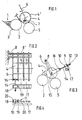
- Fig. 1 eine schematische Seitenansicht der erfindungsgemäßen Farbdosiervorrichtung;
- Fig. 2 bis 4 eine Ausführungsform der Erfindung mit pneumatischen Steuermitteln;
- Fig. 5 und 6 eine detailliertere Darstellung der Lagerung der pneumatischen Steuermittel und
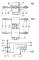
- Fig. 7 eine Steuerschaltung für die Pneumatik.
- Fig. 1 zeigt einen
herkömmlichen Farbkasten 1, der eine mit verhältnismäßig niedriger Geschwindigkeitumlaufende Farbkastenwalze 2 umfaßt, auf der beispielsweise mittels einesFarbmessers 3 eine vordosierte Farbschicht erzeugt wird.
- Figure 1 is a schematic side view of the ink metering device according to the invention.
- 2 to 4 an embodiment of the invention with pneumatic control means;
- 5 and 6 a more detailed representation of the storage of the pneumatic control means and
- Fig. 7 shows a control circuit for the pneumatics.
- 1 shows a
conventional ink fountain 1, which comprises anink fountain roller 2 rotating at a relatively low speed, on which a pre-dosed ink layer is produced, for example by means of anink knife 3.
Entsprechend dem jeweiligen Farbbedarf in den einzelnen Farbzonen wird von der Farbkastenwalze 2 mittels sich in Achsrichtung erstrekkender, voneinander beabstandeter Farbdosierelemente in Form von Scheiben 4 auf die erste, mit Maschinengeschwindigkeit angetriebene Farbwerkwalze 5, das ist der sogenannte erste Reiber, übertragen. Die Farbdösierscheiben 4 sind deshalb individuell, d.h. einzeln steuerbar, um die jeweils erforderliche Farbmenge an die Farbwerkwalze 5 zu übertragen, nachdem sie zuvor eine entsprechende Farbmenge von der vordosierten Farbschicht der Farbkastenwalze 2 übernommen haben.In accordance with the respective ink requirements in the individual ink zones, the
Damit die Farbdosierelemente 4 ständig für die Verreibung des Farbfilmes auf der ersten Farbwerkwalze 5 zur Verfügung stehen, sollen diese permanent in Anlage mit der Farbwerkwalze 5 gehalten werden. Erfindungsgemäß werden deshalb die Farbdosierelemente 4 unter Beibehaltung ihres Kontaktes zu der Farbwerkwalze 5 in Richtung Farbkastenwalze 2 entlang des Weges Y (Fig. 3) verschwenkt. Da die Farbkastenwalze eine wesentlich niedrigere Geschwindigkeit als die üblicherweise mit Maschinengeschwindigkeit umlaufende Farbwerkwalze 5 aufweist, wird erfindungsgemäß verhindert, daß die Farbdosierscheiben 4 gleichzeitig in Berührung mit der Farbkastenwalze 2 und der Farbwerkwalze 5 kommen. Die Verschwenkbewegung der Farbdosierscheiben 4 über den Weg Y wird als begrenzt. Dafür ist ein in Fig. 1 schematisch gezeigter in dem Verschwenkweg der Farbdosierelemente eingesetzter einstellbarer Anschlag 7 vorgesehen, der so justiert wird, daß jeweils die zwecks Farbübernahme an die Farbkastenwalze 2 angestellten Farbdosierelemente 4 unter Einhaltung eines Spaltes X (Fig. 1) angestellt werden. Durch Einhaltung eines derartigen Abstandes X, den sogenannten Filmspalt, kann der Geschwindigkeitsunterschied zwischen den Walzen 2 und 5 durch die Farbdosierelemente 4 überbrückt werden. In Fig. 1 ist bei 4' erkennbar, daß die Dosierscheibe unter Beibehaltung ihres Kontaktes zu der Farbwerkwalze 5 Farbe von der Farbkastenwalze 2 übernehmen kann, da der Spalt X so auf die Dicke des Farbfilmes auf der Farbkastenwalze 2 abgestimmt ist, daß ein gewisser Betrag des auf der Farbkastenwalze 2 befindlichen Farbfilmes über diesen Spalt X auf das jeweils angestellte Farbdosierelemente 4 bzw. 4' übertragbar ist. Die Farbmenge, die in den einzelnen Farbzonen erforderlich ist, kann in vorteilhafter Weise dadurch gesteuert werden, daß entweder die Anlagezeit oder die Anlagehäufigkeit der Farbdosierelemente 4 an der Farbkastenwalze 2 entsprechend variiert wird. Dies ist beispielsweise mit der in Fig. 7 gezeigten Schaltung möglich, die später noch im einzelnen beschrieben wird.So that the
Die Figuren 2 bis 7 zeigen eine vorteilhafte Ausführungsform der erfindungsgemäßen Steuerung der Farbdosierelemente 4. Wie die Figuren 2 und 3 erkennen lassen, sind die Farbdosierelemente 4 in Achsrichtung der Walzen 2, 5 nebeneinander angeordnet und voneinander beabstandet. Jedes Farbdosierelement 4 ist an mindestens einem-aber vorzugsweise zwei-etwa winkelförmigen Schwenkhebeln 6 drehbar gehalten. Ein Ende der Schwenkhebel 6 ist jeweils schwenkbar auf einer ortsfesten Welle 8 angeordnet. Untereinander sind die Schwenkhebel 6 durch Büchsen 8' auf Distanz gehalten. Das andere Ende eines jeden Schwenkhebels 6 ist mit einer Steuervorrichtung, vorzugsweise einem Hubkolben, verbunden. In dem hier beschriebenen Ausführungsbeispiel wird ein pneumatisch betätigbarer Hubkolben, bestehend aus den Kolben 9 und dem diesen umfassenden Zylinder 10, gebildet. Der Zylinder 10 ist in besonderer Weise verschwenkbar in einem Lager 11 angeordnet. Des weiteren ist die Hubbewegung des Kolbens 9 durch Mittern 12,13 einstellbar. Somit kann das Maß der Bewegung der mit dem Kolben 9 verbundenen Kolbenstange 14, die mit einem Ende eines Schwenkhebels 6 gelenkig verbunden ist, voreingestellt werden. In der Mitte des Schwenkhebels 6 ist jeweils ein Dosierelement 4 drehbar auf Zapfen 15 angeordnet, während die Kolbenstange 14 über einen Bolzen 17 mit einem Ende des Schwenkhebels 6 verbunden ist.FIGS. 2 to 7 show an advantageous embodiment of the control of the
Die Einstellung des Maßes der Verschwenkung der Schwenkhebel 6 erfolgt mit Hilfe der Muttern 12, 13 so, daß der gewünschte Abstand X bei der Anstellung der Farbdosierscheiben 4 an die Farbkastenwalze 2 eingehalten wird, wobei, wie aus Fig. 1 und 3 ersichtlich, stets ein Kontakt zwischen den Farbdosierelementen 4 und der Farbwerkwalze 5 aufrechterhalten werden soll. Zum Zwecke der Anstellung der Walze 4 in Richtung Walze 5 können z.B. die Schwenkhebel 6 jeweils über Exzenter auf der Welle 8 angeordnet sein.The setting of the degree of pivoting of the pivot lever 6 is carried out with the aid of the
Um eine derartige Bewegung, d.h. Verschwenkung der Farbdosierelemente 4 der Oberfläche der Farbwerkwalze 5 entlang, in Richtung Farbkastenwalze 2 über den Weg Y-X zu ermöglichen, ist in vorteilhafter Weise der Zylinder 10 schwenkbar in der Kammleiste 17 angeordnet. Für diesen Zweck sind an dem Zylinder 10, wie aus Fig. 2 und den Figuren 5 und 6 zu entnehmen ist, beidseitig jeweils Lagerzapfen 18, 19 vorgesehen. Die Lager 11 sind durch Lagerdeckel 20 abgedeckt. Zur Einstellung des Hubes der Kolbenstange 14 sind, wie am besten aus den Figuren 5 und 6 zu entnehmen ist, die Muttern 12, 13 auf einem Gewinde 22 angeordnet. Die Auflagen 21 dienen zur Aufnahme der Lagerdeckel 20.For such a movement, i.e. Pivoting the
Fig. 7 zeigt einen Taktgeber 23, der beispielsweise mittels eines Rechners entsprechend dem Farbbedarf in der jeweiligen Farbzone in der gewünschten Weise steuerbar ist. Dieser ist mit einem Magnetsteuerventil 24 verbunden, von dem aus zwei Steuerleitungen 25, 26 an den Zylinder 10 angelegt sind, Wird die Preßluft P' beispielsweise über die Leitung 26 an den Zylinder 10 angelegt, so wird die Kolbenstange 14 ausgefahren entsprechend dem durch die Muttern 12, 13 eingestellten, vorgegebenen Weg. Der Einzug der Kolbenstange 14 erfolgt durch Beaufschlagung mit P über die Leitungen 25 des Kolbens 10.7 shows a
Die vorangehenden Ausführungen zeigen, daß die erfindungsgemäße Farbdosiervorrichtung kompakt baut und keinerlei Stoßbelastung für den Antrieb mit sich bringt, so daß keine negative Beeinflussung des Druckes zu befürchten ist.The preceding explanations show that the ink metering device according to the invention has a compact construction and does not impose any shock load on the drive, so that there is no fear of a negative influence on the pressure.
- 1 Farbkasten1 color box
- 2 Farbkastenwalze2 ink fountain roller
- 3 Farbmesser3 color knives
- 4 Farbdosierscheibe4 color metering disc
- 5 Farbwerkswalze5 inking unit roller
- 6 Schwenkhebel6 swivel levers
- 7 Anschlag7 stop
- 8 Welle8 wave
- 9 Kolben9 pistons
- 10 Zylinder10 cylinders
- 11 Lager11 bearings
- 12 Mutter12 mother
- 13 Mutter13 mother
- 14 Kolbenstange14 piston rod
- 15 Zapfen15 cones
- 16 Bolzen16 bolts
- 17 Kammleiste17 Comb bar
- 18 Lagerzapfen18 journals
- 19 Lagerzapfen19 trunnions
- 20 Lagerdeckel20 bearing caps
- 21 Auflage21st edition
- 22 Gewinde22 threads
- 23 Taktgeber23 clock
- 24 Magnetsteuerventil24 solenoid control valve
- 25 Leitung25 line
- 26 Leitung26 line
Claims (6)
Applications Claiming Priority (2)
| Application Number | Priority Date | Filing Date | Title |
|---|---|---|---|
| DE3344776A DE3344776C1 (en) | 1983-12-10 | 1983-12-10 | Ink metering device for the inking unit of a printing machine |
| DE3344776 | 1983-12-10 |
Publications (3)
| Publication Number | Publication Date |
|---|---|
| EP0144687A2 EP0144687A2 (en) | 1985-06-19 |
| EP0144687A3 EP0144687A3 (en) | 1987-05-27 |
| EP0144687B1 true EP0144687B1 (en) | 1990-04-11 |
Family
ID=6216645
Family Applications (1)
| Application Number | Title | Priority Date | Filing Date |
|---|---|---|---|
| EP84112909A Expired - Lifetime EP0144687B1 (en) | 1983-12-10 | 1984-10-26 | Ink metering device for the inking unit of a printing machine |
Country Status (4)
| Country | Link |
|---|---|
| US (1) | US4577558A (en) |
| EP (1) | EP0144687B1 (en) |
| JP (1) | JPS60141563A (en) |
| DE (1) | DE3344776C1 (en) |
Families Citing this family (5)
| Publication number | Priority date | Publication date | Assignee | Title |
|---|---|---|---|---|
| DE3444891A1 (en) * | 1984-12-08 | 1986-06-12 | M.A.N.- Roland Druckmaschinen AG, 6050 Offenbach | Ink metering device for the inking unit of a printing machine |
| DE3733375A1 (en) * | 1987-10-02 | 1989-04-13 | Metronic Geraetebau | FLEXO PRINTING UNIT |
| DE3942525A1 (en) * | 1989-12-22 | 1991-06-27 | Licentia Gmbh | PRINT WORK WITH INK |
| US5018444A (en) * | 1990-02-28 | 1991-05-28 | Wpc Machinery Corporation | Ink applying system for a printing apparatus |
| US11383509B2 (en) * | 2018-11-09 | 2022-07-12 | Ball Corporation | Metering roller for an ink station assembly of a decorator and a method of decorating a container with the decorator |
Family Cites Families (14)
| Publication number | Priority date | Publication date | Assignee | Title |
|---|---|---|---|---|
| US1737628A (en) * | 1925-07-14 | 1929-12-03 | Wood Newspaper Mach Corp | Inking mechanism |
| DE591941C (en) * | 1932-07-30 | 1934-01-30 | Maschf Augsburg Nuernberg Ag | Inking unit for rotary printing machines |
| DE1129446B (en) * | 1957-05-14 | 1962-05-17 | Oskar Posch Dr Ing | Device for printing moving webs of fabric |
| US3063369A (en) * | 1958-07-11 | 1962-11-13 | Timson Ernest Arthur | Rotary printing machines |
| CH509156A (en) * | 1969-08-09 | 1971-06-30 | Roland Offsetmaschf | Dampening device for lithographic printing machines |
| DD104259A1 (en) * | 1973-05-08 | 1974-03-05 | ||
| US3926116A (en) * | 1974-07-01 | 1975-12-16 | Webcrafters Inc | Dampening apparatus for offset printing press |
| DE2553177A1 (en) * | 1975-02-05 | 1976-08-19 | Polygraph Leipzig | Printing machine ink or moistening appts. - has lifting roll intermittently engaging positively driven ductor roll |
| US4033262A (en) * | 1976-03-18 | 1977-07-05 | Veb Polygraph Leipzig Kombinat Fur Polygraphische Maschinen Und Ausrustungen | Ink applicator for printing apparatus |
| DE2703425B1 (en) * | 1977-01-28 | 1978-03-30 | Maschf Augsburg Nuernberg Ag | Inking unit for offset printing machines |
| DE2924635A1 (en) * | 1979-06-19 | 1981-01-15 | Gerhard Werner | Colour applicator for offset printing machine - has electronic remote control coupled to individual oscillating pick-up wheels |
| DD203704A1 (en) * | 1981-07-17 | 1983-11-02 | Matthias Schuetze | DEVICE FOR COLOR DOSING IN COLOR WORKS OF PRINTING MACHINES |
| FR2516863B1 (en) * | 1981-11-25 | 1985-11-15 | Marinoni | METHOD AND DEVICE FOR TRANSFERRING INK BETWEEN AN INK ROLL AND A FIRST INK ROLL FOR PRINTING PRESS |
| DD210535A3 (en) * | 1982-06-02 | 1984-06-13 | Polygraph Leipzig | DEVICE FOR ADJUSTING COLOR OR MOISTURE ROLLING ROLLERS |
-
1983
- 1983-12-10 DE DE3344776A patent/DE3344776C1/en not_active Expired
-
1984
- 1984-10-26 EP EP84112909A patent/EP0144687B1/en not_active Expired - Lifetime
- 1984-11-30 US US06/676,783 patent/US4577558A/en not_active Expired - Fee Related
- 1984-12-10 JP JP59259402A patent/JPS60141563A/en active Pending
Also Published As
| Publication number | Publication date |
|---|---|
| EP0144687A2 (en) | 1985-06-19 |
| US4577558A (en) | 1986-03-25 |
| DE3344776C1 (en) | 1985-05-30 |
| JPS60141563A (en) | 1985-07-26 |
| EP0144687A3 (en) | 1987-05-27 |
Similar Documents
| Publication | Publication Date | Title |
|---|---|---|
| EP0061581B2 (en) | Support for rollers that can be applied to the plate cylinder of an offset or letterpress printing machine | |
| DE2845932A1 (en) | COMBINED MOISTURE INK FOR OFFSET PRINTING | |
| EP0586881A2 (en) | Rotary web printing machine particularly for printing thick paper webs | |
| DE19756077A1 (en) | Method for operating a rotary printing press and device in a rotary printing press | |
| EP0087625B1 (en) | Device for engaging, disengaging and adjusting forme rollers at the forme cylinder of printing machines | |
| EP0623468A1 (en) | Ductor inking device and method for controlling ink supply in printing presses | |
| DE10152839A1 (en) | Positioning method for printing machine roller using control or regulation of roller magnetic bearing devices | |
| EP0144687B1 (en) | Ink metering device for the inking unit of a printing machine | |
| EP1235685B1 (en) | Inking system for a printing machine | |
| EP0144671B1 (en) | Ink metering device for the inking unit of a printing machine | |
| EP3016805B1 (en) | Method and device for mutual throwing on of two cylinders in a printing press | |
| EP0668161B1 (en) | Device for transferring individual sheets to the printing cylinder of a rotary sheet printing press | |
| EP0145904A2 (en) | Damping liquid metering device for the damping unit of a printing machine | |
| DE2902047C2 (en) | Small offset printing machine | |
| DE4403256A1 (en) | Satellite printing machine | |
| EP0534160A1 (en) | Rotary printing machine | |
| EP0210671A2 (en) | Damping device for a printing press | |
| DE3324445A1 (en) | COLOR DOSING DEVICE ON BOOK AND OFFSET PRINTING MACHINES | |
| DE3034588A1 (en) | OFFSET ROTATION PRINTING MACHINE WITH A DEVICE FOR INTERRUPTING THE DAMPENER SUPPLY | |
| DE4314426A1 (en) | Method for setting the ink quantity in vibrator inking units of printing machines, in particular sheet-fed offset printing machines, and an appropriately designed vibrator inking unit | |
| EP0033440B1 (en) | Offset printing machine | |
| DE19727387C1 (en) | Ink feed control device for printing press | |
| CH656834A5 (en) | DEVICE FOR DIAGONALLY ADJUSTING A PLATE CYLINDER OF A PRINTING MACHINE. | |
| DD153534A1 (en) | COLOR WORKING FOR AN OFFSET ROTATION PRINTING MACHINE | |
| DE846401C (en) | Rotary rubber printing |
Legal Events
| Date | Code | Title | Description |
|---|---|---|---|
| PUAI | Public reference made under article 153(3) epc to a published international application that has entered the european phase |
Free format text: ORIGINAL CODE: 0009012 |
|
| AK | Designated contracting states |
Designated state(s): CH FR GB IT LI SE |
|
| RTI1 | Title (correction) | ||
| PUAL | Search report despatched |
Free format text: ORIGINAL CODE: 0009013 |
|
| AK | Designated contracting states |
Kind code of ref document: A3 Designated state(s): CH FR GB IT LI SE |
|
| 17P | Request for examination filed |
Effective date: 19870427 |
|
| 17Q | First examination report despatched |
Effective date: 19880812 |
|
| ITF | It: translation for a ep patent filed |
Owner name: BARZANO' E ZANARDO ROMA S.P.A. |
|
| GRAA | (expected) grant |
Free format text: ORIGINAL CODE: 0009210 |
|
| AK | Designated contracting states |
Kind code of ref document: B1 Designated state(s): CH FR GB IT LI SE |
|
| ET | Fr: translation filed | ||
| GBT | Gb: translation of ep patent filed (gb section 77(6)(a)/1977) | ||
| PLBE | No opposition filed within time limit |
Free format text: ORIGINAL CODE: 0009261 |
|
| STAA | Information on the status of an ep patent application or granted ep patent |
Free format text: STATUS: NO OPPOSITION FILED WITHIN TIME LIMIT |
|
| 26N | No opposition filed | ||
| PGFP | Annual fee paid to national office [announced via postgrant information from national office to epo] |
Ref country code: GB Payment date: 19910808 Year of fee payment: 8 |
|
| PGFP | Annual fee paid to national office [announced via postgrant information from national office to epo] |
Ref country code: FR Payment date: 19910911 Year of fee payment: 8 |
|
| PGFP | Annual fee paid to national office [announced via postgrant information from national office to epo] |
Ref country code: CH Payment date: 19910917 Year of fee payment: 8 |
|
| PGFP | Annual fee paid to national office [announced via postgrant information from national office to epo] |
Ref country code: SE Payment date: 19910923 Year of fee payment: 8 |
|
| ITTA | It: last paid annual fee | ||
| PG25 | Lapsed in a contracting state [announced via postgrant information from national office to epo] |
Ref country code: GB Effective date: 19921026 |
|
| PG25 | Lapsed in a contracting state [announced via postgrant information from national office to epo] |
Ref country code: SE Effective date: 19921027 |
|
| PG25 | Lapsed in a contracting state [announced via postgrant information from national office to epo] |
Ref country code: LI Effective date: 19921031 Ref country code: CH Effective date: 19921031 |
|
| GBPC | Gb: european patent ceased through non-payment of renewal fee |
Effective date: 19921026 |
|
| PG25 | Lapsed in a contracting state [announced via postgrant information from national office to epo] |
Ref country code: FR Effective date: 19930630 |
|
| REG | Reference to a national code |
Ref country code: CH Ref legal event code: PL |
|
| REG | Reference to a national code |
Ref country code: FR Ref legal event code: ST |
|
| EUG | Se: european patent has lapsed |
Ref document number: 84112909.1 Effective date: 19930510 |