EP0924046A2 - Verfahren und Vorrichtung zur Analyse von Betriebsstörungen bei einer Spritzgiessmaschine - Google Patents
Verfahren und Vorrichtung zur Analyse von Betriebsstörungen bei einer Spritzgiessmaschine Download PDFInfo
- Publication number
- EP0924046A2 EP0924046A2 EP98310243A EP98310243A EP0924046A2 EP 0924046 A2 EP0924046 A2 EP 0924046A2 EP 98310243 A EP98310243 A EP 98310243A EP 98310243 A EP98310243 A EP 98310243A EP 0924046 A2 EP0924046 A2 EP 0924046A2
- Authority
- EP
- European Patent Office
- Prior art keywords
- alarm
- time
- type
- data regarding
- alarms
- Prior art date
- Legal status (The legal status is an assumption and is not a legal conclusion. Google has not performed a legal analysis and makes no representation as to the accuracy of the status listed.)
- Granted
Links
- 238000001746 injection moulding Methods 0.000 title claims abstract description 188
- 238000000034 method Methods 0.000 title claims abstract description 35
- 238000004519 manufacturing process Methods 0.000 claims abstract description 99
- 230000000694 effects Effects 0.000 claims abstract description 36
- 239000000725 suspension Substances 0.000 claims description 137
- 238000000465 moulding Methods 0.000 claims description 128
- 239000011347 resin Substances 0.000 claims description 70
- 229920005989 resin Polymers 0.000 claims description 70
- 238000013480 data collection Methods 0.000 claims description 20
- 230000005540 biological transmission Effects 0.000 claims description 12
- 238000012545 processing Methods 0.000 abstract description 196
- 238000004458 analytical method Methods 0.000 description 239
- 238000013500 data storage Methods 0.000 description 75
- 239000000047 product Substances 0.000 description 32
- 238000004364 calculation method Methods 0.000 description 9
- 230000002411 adverse Effects 0.000 description 6
- 238000012546 transfer Methods 0.000 description 5
- 239000006227 byproduct Substances 0.000 description 4
- 230000002159 abnormal effect Effects 0.000 description 2
- 238000011156 evaluation Methods 0.000 description 2
- 238000002347 injection Methods 0.000 description 2
- 239000007924 injection Substances 0.000 description 2
- YDLQKLWVKKFPII-UHFFFAOYSA-N timiperone Chemical compound C1=CC(F)=CC=C1C(=O)CCCN1CCC(N2C(NC3=CC=CC=C32)=S)CC1 YDLQKLWVKKFPII-UHFFFAOYSA-N 0.000 description 2
- 229950000809 timiperone Drugs 0.000 description 2
- 238000004891 communication Methods 0.000 description 1
- 230000006870 function Effects 0.000 description 1
- 238000012423 maintenance Methods 0.000 description 1
Images





Classifications
-
- G—PHYSICS
- G07—CHECKING-DEVICES
- G07C—TIME OR ATTENDANCE REGISTERS; REGISTERING OR INDICATING THE WORKING OF MACHINES; GENERATING RANDOM NUMBERS; VOTING OR LOTTERY APPARATUS; ARRANGEMENTS, SYSTEMS OR APPARATUS FOR CHECKING NOT PROVIDED FOR ELSEWHERE
- G07C3/00—Registering or indicating the condition or the working of machines or other apparatus, other than vehicles
-
- B—PERFORMING OPERATIONS; TRANSPORTING
- B29—WORKING OF PLASTICS; WORKING OF SUBSTANCES IN A PLASTIC STATE IN GENERAL
- B29C—SHAPING OR JOINING OF PLASTICS; SHAPING OF MATERIAL IN A PLASTIC STATE, NOT OTHERWISE PROVIDED FOR; AFTER-TREATMENT OF THE SHAPED PRODUCTS, e.g. REPAIRING
- B29C45/00—Injection moulding, i.e. forcing the required volume of moulding material through a nozzle into a closed mould; Apparatus therefor
- B29C45/17—Component parts, details or accessories; Auxiliary operations
- B29C45/76—Measuring, controlling or regulating
-
- B—PERFORMING OPERATIONS; TRANSPORTING
- B29—WORKING OF PLASTICS; WORKING OF SUBSTANCES IN A PLASTIC STATE IN GENERAL
- B29C—SHAPING OR JOINING OF PLASTICS; SHAPING OF MATERIAL IN A PLASTIC STATE, NOT OTHERWISE PROVIDED FOR; AFTER-TREATMENT OF THE SHAPED PRODUCTS, e.g. REPAIRING
- B29C2945/00—Indexing scheme relating to injection moulding, i.e. forcing the required volume of moulding material through a nozzle into a closed mould
- B29C2945/76—Measuring, controlling or regulating
- B29C2945/76003—Measured parameter
- B29C2945/7604—Temperature
-
- B—PERFORMING OPERATIONS; TRANSPORTING
- B29—WORKING OF PLASTICS; WORKING OF SUBSTANCES IN A PLASTIC STATE IN GENERAL
- B29C—SHAPING OR JOINING OF PLASTICS; SHAPING OF MATERIAL IN A PLASTIC STATE, NOT OTHERWISE PROVIDED FOR; AFTER-TREATMENT OF THE SHAPED PRODUCTS, e.g. REPAIRING
- B29C2945/00—Indexing scheme relating to injection moulding, i.e. forcing the required volume of moulding material through a nozzle into a closed mould
- B29C2945/76—Measuring, controlling or regulating
- B29C2945/76003—Measured parameter
- B29C2945/76066—Time
- B29C2945/7607—Time start
-
- B—PERFORMING OPERATIONS; TRANSPORTING
- B29—WORKING OF PLASTICS; WORKING OF SUBSTANCES IN A PLASTIC STATE IN GENERAL
- B29C—SHAPING OR JOINING OF PLASTICS; SHAPING OF MATERIAL IN A PLASTIC STATE, NOT OTHERWISE PROVIDED FOR; AFTER-TREATMENT OF THE SHAPED PRODUCTS, e.g. REPAIRING
- B29C2945/00—Indexing scheme relating to injection moulding, i.e. forcing the required volume of moulding material through a nozzle into a closed mould
- B29C2945/76—Measuring, controlling or regulating
- B29C2945/76003—Measured parameter
- B29C2945/76066—Time
- B29C2945/76073—Time termination
-
- B—PERFORMING OPERATIONS; TRANSPORTING
- B29—WORKING OF PLASTICS; WORKING OF SUBSTANCES IN A PLASTIC STATE IN GENERAL
- B29C—SHAPING OR JOINING OF PLASTICS; SHAPING OF MATERIAL IN A PLASTIC STATE, NOT OTHERWISE PROVIDED FOR; AFTER-TREATMENT OF THE SHAPED PRODUCTS, e.g. REPAIRING
- B29C2945/00—Indexing scheme relating to injection moulding, i.e. forcing the required volume of moulding material through a nozzle into a closed mould
- B29C2945/76—Measuring, controlling or regulating
- B29C2945/76003—Measured parameter
- B29C2945/76163—Errors, malfunctioning
Definitions
- the present invention relates to a method of and an apparatus for analyzing alarms of an injection molding machine.
- an operating time analyzer for individually summing up and displaying time periods of manual operation, an automatic operation and an alarm occurrence in Japanese Patent Publication No. 4-341817. This apparatus sums up and displays the alarm occurrence time and does not clearly provide a relationship between the alarm and the production time etc.
- Some examples provide a method of and an apparatus for analyzing alarms of an injection molding machine in which the relation between the alarm and the production time can be grasped clearly and also various kinds of statistical processing can be performed in accordance with an operator's request.
- the number of alarms, a ratio of the number of alarms to operating time of an injection molding machine or a ratio of the number of alarms of a selected item to the total number of alarms is totalized and displayed with respect to a time zone, a type of resin used or a production schedule.
- the suspension time caused by alarms, a ratio of the suspension time to the operating time or a ratio of the suspension time to the number of alarms may be totalized and displayed with respect to an item selected from items of a time zone, a product, a type of alarm, an alarm group, a resin used and production schedule.
- the number of alarms, a ratio of the number of alarms to the production time or a ratio of the number of alarms on a selected item to the total number of alarms are totalized and displayed with respect to combined two or more items selected from items of a time zone, a product, a type of alarm, an alarm group, a type of resin and a production schedule;
- the aforementioned various totalizing results may be displayed by numerical values or a graph.
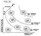
- a relationship between the number of alarms and an average operation suspension time for one alarm may be displayed for each element of aforesaid item by a graph.
- contour lines on which a product of the number of alarms and the average suspension time is a set value, on a graph a degree of effect caused by each element of alarm on the molding operation can be grasped easily.
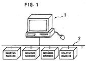
- FIG. 1 is a schematic view showing one example of an injection molding work facility according to one embodiment to which an alarm analyzing method of the present invention is applied
- FIG. 1 shows a facility configured so that data are collected from a plurality of injection molding machines via a data transmission path 2 by a host computer 1 consisting of a personal computer etc.
- the host computer 1 is provided with data input means such as a keyboard and mouse and a monitor etc.
- Each of the injection molding machines is correspondingly equipped with a CNC unit as a dedicated controller.
- the CNC unit of each injection molding machine has a function of detecting a trouble in molding work including an abnormal temperature of an injection cylinder and a metering trouble and a trouble of the injection molding machine itself including a trouble of a servo system or an over-travel of a movable member.
- the code of alarm occurring at the present time is automatically stored in an alarm detecting register N.
- the CNC unit of the injection molding machine of this embodiment is provided with an alarm code storage register M for storing only the latest one of the values of alarms which occurred in the past.
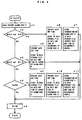
- the CNC unit of the injection molding machine which started alarm data collection processing in each predetermined cycle according to the flowchart shown in FIG. 4, first reads the alarm code stored in the alarm detecting register N at this time (Step a1), and then judges whether that value is a value other than zero, that is, whether any alarm occurrence regarding the molding work and the injection molding machine itself is stored in the alarm detecting register N, and whether zero is stored in the alarm code storage register M, in effect, whether the alarm occurrence continuing from the previous processing cycle is stored in the alarm code storage register M (Step a2).
- Step a2 If the judgment result of Step a2 is Yes, that is, if the value of the alarm code storage register M is zero and any alarm code is stored in the alarm detecting register N, the result means that no alarm has been detected for a while and a new alarm is detected in this processing cycle. Therefore, the CNC unit of the injection molding machine stores the alarm code stored in the alarm detecting register N and the present date and time, that is, the date and time when the alarm detected at this time occurs, in an alarm data storage file of the CNC unit (Step a6).
- the CNC unit reads the code of alarm group to which the alarm N belongs, the information concerning the product which is being molded by the injection molding machine at present, and other information from an alarm code file, a schedule control file (not shown) for the injection molding machine, etc., and stores these data, in addition to the alarm code N and the date and time of occurrence, in each field of the same record in the alarm data storage file (Step a7).
- the alarm group described here consists dividedly of, for example, an alarm group relating to abnormal temperature, an alarm group relating to a trouble of electrical system, an alarm group relating to an operation error, an alarm group relating to a trouble of motor, and an alarm group relating to a trouble of controller.
- the alarms can be grouped at a higher level of concept, for example, into a molding facility alarm group relating to a molding facility such as a molding machine, mold, temperature controller, dryer, and take-out device, and a product element alarm group relating to an element constituting a product itself including a trouble of resin and insert member.
- FIG. 5 One example of the alarm data storage file provided in the CNC unit of the injection molding machine is shown in FIG. 5.
- the alarm data storage file has fields for storing data of items of Start Date/Time, End Date/Time, Alarm Code, Alarm Group, Production No., Schedule No., and Resin Type for each Alarm ID, that is, for each record corresponding to the series number constituting the address. Of these items, only the dab of Start Date/Time (the date and time when the alarm detected at this time occurred) and Alarm Code are stored by the processing in Step a6.
- the alarm code file, schedule control file etc. of the injection molding machine are referred to by the CNC unit, and Alarm Group (the code of alarm group to which the present alarm belongs) and the information concerning the product which is being molded by the injection molding machine at present such as Product No. (product code), Schedule No. (schedule code), and Resin Type (resin code), are stored in the corresponding field of the same record as described before in the alarm data storage file.
- Alarm Group the code of alarm group to which the present alarm belongs
- Resin Type Resin code
- Step a3 the CNC unit further judges whether the value of the alarm detecting register N is zero, that is, whether a new alarm is detected in the present processing cycle, and whether the value of the alarm code storage register M is a value other than zero, in effect, the alarm occurrence continuing from the previous processing cycle is stored in the alarm code storage register M (Step a3).
- Step a3 If the judgment result of Step a3 is Yes, that is, if the value of the alarm code storage register M is a value other than zero and an alarm code is not stored in the alarm detecting register N, the result means that the alarm M having been detected for a while is canceled in the present processing cycle. Therefore, the CNC unit of the injection molding machine stores the present date and time, that is, the date and time when the alarm code stored in the alarm code storage register M is canceled, in the field of the same record as described before in the alarm data storage file of the CNC unit so as to correspond to the aforesaid alarm code M (Step a8).
- Step a9 In the field of End Date/Time (date and time of alarm end) in the alarm data storage file, which has been blank in the process of Steps a6 and a7, the date and time of alarm end is written a this time. As described later, in some cases, the equivalent processing to this processing is performed by the processing of Step a9.
- Step a3 the CNC unit judges whether the value of the alarm detecting register N and the value of the alarm code storage register M are different from each other (Step a4).
- Step a4 If the judgment result of Step a4 is Yes, that is, if the value of the alarm detecting register N and the value of the alarm code storage register M are different from each other, the result means that the occurrence of a new alarm N is detected in place of the alarm M continuing from the previous processing cycle. Therefore, the CNC unit of the injection molding machine stores the present date and time, that is, the date and time when the previous alarm code stored in the alarm code storage register M is canceled, in the field of the same record as described before in the alarm data storage file of the CNC unit so as to correspond to the aforesaid alarm code M (Step a9).
- the CNC unit stores the same present date and time in the corresponding field of the next record in the alarm data storage file as the date and time of the occurrence of a new alarm code N (Step a10). Further, the CNC unit reads the code of alarm group to which that alarm code N belongs and the information concerning the product which is being molded by the injection molding machine at present from the alarm code file, the schedule control file, etc. of the injection molding machine in the same way as described before, and stores these data, in addition to the alarm code N and the date and time of occurrence, in the corresponding field of the same record in the alarm data storage file (Step a11).
- the CNC unit of the injection molding machine transfers the value of the alarm detecting register N to the alarm code storage register M, and re-stores the alarm information N detected in the present cycle as the alarm information M in the previous cycle for the alarm data collection processing in the next processing cycle (Step a5).
- the alarm data collection processing in this cycle is finished.
- the alarm data storage file are finally stored the items of Start Date/Time (date and time of alarm occurrence), End Date/Time (date and time of alarm end), Alarm code, Alarm Group (alarm group code), Product No. (product code), Schedule No. (schedule code), and Resin Type (resin code) in the field of each record in time sequence corresponding to the occurrence state of alarm as shown in FIG. 5.
- Alarm ID is merely an address value, having no special meaning.
- the CNC unit of the injection molding machine which started production result data collection processing in each predetermined cycle according to the flowchart shown in FIG. 6, first reads the schedule code stored in a schedule code detecting register R at the present time, that is, the number of the molding schedule being executed at present (Step b1), and judges whether the value of the schedule code detecting register R and the value of a schedule code storage register Q which stores only the latest one of the values of schedule code executed in the past are larger than zero, and whether the value of the schedule code detecting register R and the value of the schedule code storage register Q are different from each other (Step b2).
- Step b2 If the judgment result of Step b2 is Yes, that is, if the value of the schedule code detecting register R and the value of the schedule code storage register Q are different from each other and both of these values are larger than zero, the result means that the injection molding work of schedule code Q having executed up to this time is finished and the injection molding work of the next schedule, in effect, the injection molding work of schedule code R is newly started. Therefore, the CNC unit stores the present date and time, that is, the date and time when the injection molding work having been stored in the schedule code storage register Q is finished, in a field of a production result data storage file of the CNC unit so as to correspond to the aforesaid schedule code Q (Step b6).
- the CNC unit stores, together with the schedule code R, the same present date and time in the corresponding field of the next record in the production result data storage file as the date and time when a new injection molding work is started (Step b7). Further, the CNC unit reads the information concerning the schedule R from the schedule control file etc. of the injection molding machine, and stores the data in the production result data storage file so as to correspond to the field of schedule code R (Step b8).
- FIG. 7 One example of the production result data storage file provided in the CNC unit of the injection molding machine is shown in FIG. 7.
- the production result data storage file has fields for storing data of items of Start Date/Time, End Date/Time, Schedule No., Production No., and Resin Type for each record corresponding to the serial number constituting the address.
- Step b2 the CNC unit further judges whether the schedule code stored in the schedule code detecting register R at this time is zero, and whether the value of the schedule code storage register Q is larger than zero (Step b3).
- Step b3 If the judgment result of Step b3 is Yes, the result means that the molding work of schedule code Q having been executed by the injection molding machine up to this time is finished, and moreover the value of the schedule code detecting register R is zero and the injection molding work of the next schedule is not started. Therefore, the CNC unit stores the present date and time, that is, the date and time when the injection molding work having been stored in the schedule code storage register Q is finished, in the field of the production result data storage file of the CNC unit so as to correspond to the aforesaid schedule code Q in the same way as the processing in Step b6 (Step b9).
- Step b3 the CNC unit further judges whether the schedule code stored in the schedule code detecting register R at this tune is a value other than zero, and whether the value of the schedule code storage register Q is zero (Step b4).
- Step b4 If the judgment result of Step b4 is Yes, the result means that the value of the schedule code storage register Q is zero, and the injection molding machine which has been in a suspension state started the next injection molding work again. Therefore, the CNC unit stores, together with the schedule code R, the present date and time in the corresponding field of the next record in the production result data storage file as the date and time when new injection molding work of schedule code R is started (Step b10). Further, the CNC unit reads the information concerning the schedule code R, that is, the Product No. and Resin Type from the schedule control file etc. of the injection molding machine, and stores the data in the production result data storage file so as to correspond to the field of schedule code R (Step b11).
- the production result data collection processing in this cycle is finished.
- the alarm data storage file and the production result data storage file are provided in both of the CNC unit of the injection molding machine and the host computer 1. In this case, each time the alarm data or the production result data is newly stored in the CNC unit of the injection molding machine, the data is transferred to the side of the host computer 1. Therefore, it is necessary only that the latest one data can be stored at a minimum in the alarm data storage file and the production result data storage file on the side of the CNC unit.
- FIG. 8 briefly shows processing in each predetermined cycle in the case where the data are controlled collectively on the side of the host computer 1 to generate the alarm data storage file and the production result data storage file.
- the host computer 1 first initializes the value of index k for identifying Machine No. of the injection molding machine with which the host computer 1 communicates to 1 (Step c1), and establishes a communication state with the CNC unit of the injection molding machine of Machine No. (k) based on the value of the index k (Step c2). Then, the host computer 1 waits until the data in the alarm detecting register N, alarm code storage register M, schedule code detecting register R, schedule code storage register Q, and the like are transferred from the CNC unit (Step c3), and temporarily stores the data in a memory after the data are transferred.
- the host computer 1 performs the processing equivalent to the alarm data collection processing shown in FIG. 4 based on the data of the alarm detecting register N, alarm code storage register M, and the like stored in the memory, and stores the data of the items of Start Date/Time (date and time of alarm occurrence), End Date/Time (date and time of alarm end), Alarm Code, Alarm Group (alarm group code), Product No. (product code), Schedule No. (schedule code), and Resin Type (resin code) in an alarm data storage file in the host computer 1 so as to correspond to the aforesaid Machine No. (k) (Step c5).
- the alarm data storage file in the host computer 1, shown in FIG. 9, is the same as the alarm data storage file shown in FIG. 5 except that Machine No. is present.
- the host computer 1 further performs the processing equivalent to the production result data collection processing shown in FIG. 6 based on the data of the schedule code detecting register R, schedule code storage register Q, and the like stored in the memory, and stores the data of the items of Start Date/Time (date and time of start of molding work), End Date/Time (date and time of end of molding work), Schedule No. (schedule code), Product No. (product code), and Resin Type (resin code) in a production result data storage file in the host computer 1 so as to correspond to the aforesaid Machine No. (k) (Step c5).
- the production result data storage file in the host computer 1, shown in FIG. 10, is the same as the production result data storage file shown in FIG. 7 except that Machine No. is present.
- the host computer 1 After finishing the registration processing of data in the alarm data storage file and the production result data storage file, the host computer 1 then judges whether the transfer request for schedule data is given from the CNC unit of injection molding machine of Machine No. (k)(Step c6). If the transfer request is given, the host computer 1 transfers the data such as Schedule No., Product No., Resin Type, scheduled date and time of start of molding, and scheduled date and time of end of molding regarding the next operation schedule to the CNC unit of injection molding machine of Machine No. (k) (Step c7).
- Step c7 when the schedule data are set manually in the CNC unit of the injection molding machine, or when the schedule control file is provided in the CNC unit itself of the injection molding machine, the processing in Step c7 need not be performed.
- the host computer 1 adds 1 to the value of the index k (Step c8), and judges whether the value of the index k exceeds the value of the final value Nmax of Machine No. of injection molding machine (Step c9).
- the host computer 1 connects with the CNC unit of the next Machine No. in the same way as described before based on the value of the index k updated by the processing in Step c8, executes the processing in Steps c2 to c9 repeatedly, and takes in the data of each injection molding machine in succession in the alarm data storage file and the production result data storage file of the host computer 1.
- Step c9 becomes Yes, so that the processing in one processing cycle in the host computer 1 is completed.
- the alarm data storage file in the host computer 1 are finally stored the data of the items of Machine No. (machine number of injection molding machine), Start Date/Time (date and time of alarm occurrence), End Date/Time (date and time of alarm end), Alarm Code, Alarm Group (alarm group code), Product No. (product code), Schedule No. (schedule code), and Resin Type (resin code) in time sequence according to the occurrence state of alarm as shown in FIG. 9. Also, in the production result data storage file in the host computer 1 are stored the data of the items of Machine No.
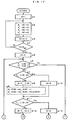
- alarm analysis processing in this embodiment will be described with reference to the flowcharts shown in FIGS. 11 to 13, showing an example of the case where the alarm data storage file and the production. result data storage file are provided on the side of the host computer 1.
- This processing is executed by inputting a selection command of alarm history screen to the host computer 1 by the operator's operation of a keyboard, mouse, or the like.
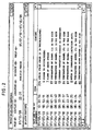
- the host computer 1 which detected the selection of alarm history screen and started alarm analysis processing (Step d1), first reads the alarm data storage file shown in FIG. 9 (Step d2), and displays a list of history of alarms occurring for the analysis period set by default on an alarm history display screen as shown in FIG. 2 (Step d3). As shown in FIG. 2, only Start Date/Time (date and time of alarm occurrence) and Alarm Code are actually displayed. Of these, the portion of Alarm Code is converted into a text form which can be directly understood by the operator by referring to a reference file etc. which store Alarm Code and character strings so as to correspond to each other. For example, "3 servo system is in trouble" is displayed on the monitor screen. The default value of analysis period is displayed for the whole period, and the portion which cannot be displayed on the monitor screen is displayed by page up or page down by the operation of a scroll box.
- the host computer 1 enters a writing state to wait the selection operation of analysis period setting screen (Step d4), the selection operation of alarm analysis screen (Step d9), or the selection operation of alarm history screen end (Step d22) by the operator.
- the analysis period setting screen is a setting screen for inputting a period etc. for which alarm analysis is made
- the alarm analysis screen is a screen for displaying the analysis results
- the alarm history screen end is a keyboard or mouse operation for ending the alarm analysis processing.
- the operator When setting or changing the period etc. for which alarm analysis is made, the operator first selects an analysis condition setting screen, and inputs the alarm analysis period etc. on that screen.
- the host computer 1 which detected the selection operation of analysis condition setting screen by the judgment processing in Step d4, displays the analysis period setting screen (Step d5), and thereafter waits until the input operation of the alarm analysis period etc. is performed by the operator. If the input operation is performed by the operator, the host computer 1 judges whether the newly set alarm analysis period is equal to the default value stored at this time (Step d6). If the newly set alarm analysis period is equal to the default value stored at this time, the host computer 1 keeps the default value as it is, ignoring the input operation of this time. If the newly set alarm analysis period is different from the default value stored at this time, the host computer 1 updates and stores the newly set alarm analysis period (Step d7). The date and time when the alarm analysis period starts is stored as S, and the date and time when the alarm analysis period ends is stored as E.
- FIG. 2 shows, as one example, the case where the period from January 10, 1997, to October 9, 1997, is set as the alarm analysis period.
- Steps d6 to d8 The processing in Steps d6 to d8 is executed repeatedly until the end of the alarm analysis period setting screen is selected. Therefore, retrying work etc. for correcting a mistakenly input alarm analysis period are easy to perform. After setting a desired alarm analysis period, the operator selects the end of the analysis period setting screen, thereby exiting this routine (Step d8).
- the operator selects the alarm analysis screen, selects desired statistical processing, and thereafter makes the host computer 1 perform automatic processing according to the aforementioned alarm analysis period S and E.
- the host computer 1 which detected the selection of the alarm analysis screen in the processing in Step d9, first sums up the total number of alarm occurrences according to the stored alarm analysis period (Step d10).
- Step d10 is executed by searching the alarm data storage file shown in FIG. 9 and simply counting the number of items of Start Date/Time included in the period from start to end of the alarm analysis period.
- the host computer 1 sums up the suspension time of the injection molding machine caused by an alarm according to the stored alarm analysis period (Step d11). Like the aforementioned processing in Step 10, this processing is also performed by searching the alarm data storage file shown in FIG. 9 and simply summing up the suspension time of injection molding machine caused by an alarm. Specifically, this processing is performed by obtaining the suspension time caused by an alarm by subtracting the value of Start Date/Time from the value of End Date/Time of each record included in the period from start to end of the alarm analysis period, and by summing up the values for all records for the aforesaid period.
- the situation differs between the short operating time (production time) of injection molding machine and the long operation time thereof. That is to say, even if the number of alarm occurrences and the suspension time of injection molding machine caused by alarm occurrence are equal, when the operating time of injection molding machine is long, the ratio of the number of alarm occurrences and the suspension time of injection molding machine caused by alarm occurrence is relatively low, and when the operation time of injection molding machine is short, the ratio of the number of alarm occurrences and the suspension time of injection molding machine caused by alarm occurrence is relatively high.
- Step 12 processing (total operating time calculation processing) in Step 12 for obtaining the total operating time (total production time) of injection molding machine for the analysis period will be explained with reference to the flowchart shown in FIG. 14.
- the host computer 1 which started the total operating time calculation processing, first initializes the value of a total operating time integrating register Sum to zero (Step e1), and sets an initial value 1 to a Schedule ID search index (Step e2).
- the host computer 1 accesses the production result data storage file shown in FIG. 10 to read a record in which the value of data address agrees with the present value of the Schedule ID search index, reads the value Ts (ID) of field of Start Date/Time (date and time of start of molding work) and the value Te (ID) of field of End Date/Time (date and time of end of molding work) of that record, and judges whether the date and time of start of molding work Ts (ID) is date and time after the end of alarm analysis period E in time sequence, and whether the date and time of end of molding work Te (ID) is date and time before the start of alarm analysis period S in time sequence (Step e3).
- Step e3 If the judgment result of Step e3 is Yes, that is, if the date and time of start of molding work Ts (ID) of that record is date and time after the end of alarm analysis period E in time sequence, or the date and time of end of molding work Te (ID) is date and time before the start of alarm analysis period S in time sequence, the result means that the data of that record are not included in the alarm analysis period, for example, in the period from February 5, 1997, to August 4, 1997 of the aforementioned example. Therefore, the host computer 1 skips Step e4 and the following steps and adds 1 to the value of the Schedule ID search index (Step e11).
- Step e3 If the judgment result of Step e3 is No, the result means that a part or the whole of the period of molding work of that record is included in the alarm analysis period. Therefore, the host computer 1 first determines the earliest date and time A of molding work of that record included in the alarm analysis period.
- Step e4 a judgment is made as to whether the date and time of start of molding work Ts (ID) of that record is date and time before the start of alarm analysis period S in time sequence. If the date and time of start of molding work Ts (ID) is date and time after the start of alarm analysis period S m tune sequence, the date and time of start of molding work Ts (ID) is the earliest date and time A of molding work of that record (Step e5).
- Step e6 If the date and time of start of molding work Ts (ID) is date and time before the start of alarm analysis period S in time sequence, the time before the date and time of start of alarm analysis period S is invalid, and the date and time of start of alarm analysis period S itself is the earliest date and time A of molding work of that record included in the alarm analysis period (Step e6).
- the host computer 1 determines the latest date and time B of molding work of that record included in the alarm analysis period.
- the host computer 1 judges whether the date and time of end of molding work Te (ID) of that record is date and time after the end of alarm analysis period E in time sequence (Step e7). If the date and time of end of molding work Te (ID) of that record is date and time before the end of alarm analysis period E in time sequence, the date and time of end of molding work Te (ID) is the latest date and time B of molding work of that record (Step e8).
- Step e9 If the date and time of end of molding work Te (ID) of that record is date and time after the end of alarm analysis period E in time sequence, the time after the date and time of end of alarm analysis period E is invalid, and the date and time of end of alarm analysis period E itself is the latest date and time B of molding work of that record included in the alarm analysis period (Step e9).
- the host computer 1 determines the molding work time of that record included in the alarm analysis period by subtracting the earliest date and time A of molding work of that record from the latest date and time B of molding work of that record, and adds this time to the total operating time integrating register Sum (Step e10).
- the host computer 1 adds 1 to the value of the Schedule ID search index (Step e11), and judges whether the present value of the Schedule ID search index exceeds the final value IDmax of data address of the production result data storage file (Step e12).
- the host computer 1 proceeds again to the processing in Step e3, accesses the production result data storage file shown in FIG. 10 based on the value of the Schedule ID search index updated by the processing in Step e11, and reads the value Ts (ID) of Start Date/Time and the value Te (ID) of End Date/Time of the next data address, by which the same processing as described before is repeatedly executed.
- the host computer 1 which determined the total operating time (total production time) of injection molding machine for the alarm analysis period by the processing in Step d12, then displays an alarm analysis screen including classification items and detailed classification items as shown in FIG. 3 on the monitor (Step d13). Further, the host computer 1 displays the number of alarm occurrences for the analysis period summed up by the processing in Step d10 and the total suspension time of injection molding machine for the analysis period summed up by the processing in Step d11 in the column of TOTAL (Step d14), and enters a waiting state to wait for the operator to select an arbitrary classification item from the pull-down menu of classification items (Step d15).
- the classification items include item by machine, by resin, by time zone, by schedule, by alarm, by alarm group, by product, and so on. This item classification is also applied to the detailed classification items.
- the host computer 1 detects this operation by judgment processing in Step d15, stores the selected classification item U, for example, item by machine, and starts the processing in Step d16 to individually obtain the operating time of injection molding machine for each element of classification item based on the selected classification item.
- Step d16 the processing (total operating time calculation processing by classification item element) in Step d16 to individually obtain the operating time of injection molding machine based on the classification item will be explained with reference to the flowcharts shown in FIGS. 15 and 16.
- the host computer 1 which started the total operating time calculation processing by classification item element, first sets an initial value 1 to an element identification index k for identifying the element of classification item (Step f1). After initializing the value of a total operation time integrating register by classification item element Sum (k) corresponding to the index k to zero (Step f2), the host computer 1 adds 1 to the value of the index k (Step f3), and then judges whether the value of the index k exceeds the value of the number of elements Xmax of classification item (Step f4).
- the total operation time integrating register by classification item element Sum (k) is a register for storing the total operating time of each injection molding machine.
- the value of the number of elements Xmax in this case is the total number of injection molding machines connected to the host computer 1.
- the total operation time integrating register by classification item element Sum (k) is a register for storing the total time of injection molding work for each resin.
- the value of the number of elements Xmax in this case is the total number of types of various resins used for the injection molding work.
- Step f4 If the judgment result of Step f4 is No, the result means that there is another total operation time integrating register by classification item element Sum (k) to be initialized. Therefore, the host computer 1 proceeds again to the processing in Step f2, and repeatedly executes the processing to initialize the value of the total operation time integrating register by classification item element Sum (k) corresponding to the element identification index k updated by the processing in Step f3 to zero.
- Step f4 the same processing as described above is repeatedly executed until the judgment result of Step f4 becomes Yes.
- the host computer 1 sets an initial value 1 to the Schedule ID search index (Step f5), accesses the production result data storage file shown in FIG. 10 to read a record in which the value of data address agrees with the present value of the Schedule ID search index, reads the value Ts (ID) of field of Start Date/Time (date and time of start of molding work) and the value Te (ID) of field of End Date/Time (date and time of end of molding work) of that record, and judges whether the date and time of start of molding work Ts (ID) is date and time after the end of alarm analysis period E in time sequence, and whether the date and time of end of molding work Te (ID) is date and time before the start of alarm analysis period S in time sequence (Step f6).
- Step f6 If the judgement result of Step f6 is Yes, that is, if the date and time of start of molding work Ts (ID) of that record is date and time after the end of alarm analysis period E in time sequence, or the date and time of end of molding work Te (ID) is date and time before the start of the alarm analysis period S in time sequence, the result means that the data of that record are not included in the alarm analysis period, for example, in the period from February 5, 1997, to August 4, 1997 of the aforementioned example. Therefore, the host computer 1 skips Step f7 and the following steps and adds 1 to the value of the Schedule ID search index (Step f15).
- Step f6 If the judgement result of Step f6 is No, the result means that a part or the whole of the period of molding work of that record is included in the alarm analysis period. Therefore, the host computer 1 first determines the earliest date and time A of molding work of that record included in the alarm analysis period.
- Step f7 a judgment is made as to whether the date and time of start of molding work Ts (ID) of that record is date and time before the start of alarm analysis period S in time sequence. If the date and time of start of molding work Ts (ID) is date and time after the start of alarm analysis period S in time sequence, the date and time of start of molding work Ts (ID) is the earliest date and time A of molding work of that record (Step f8).
- Step f9 If the date and time of start of molding work Ts (ID) is date and time before the start of alarm analysis period S in time sequence, the time before the date and time of start of alarm analysis period S is invalid, and the date and time of start of alarm analysis period S itself is the earliest date and time A of molding work of that record included in the alarm analysis period (Step f9).
- the host computer 1 determines the latest date and time B of molding work of that record included in the alarm analysis period.
- the host computer 1 judges whether the date and time of end of molding work Te (ID) of that record is date and time after the end of alarm analysis period E in time sequence (Step f10). If the date and time of end of molding work Te (ID) of that record is date and time before the end of alarm analysis period E in time sequence, the date and time of end of molding work Te (ID) is the latest date and time B of molding work of that record (Step f11).
- Step f12 If the date and time of end of molding work Te (ID) of that record is date and time after the end of alarm analysis period E in time sequence, the time after the date and time of end of alarm analysis period E is invalid, and the date and time of and of alarm analysis period E itself is the latest date and time B of molding work of that record included in the alarm analysis period (Step f12).
- the host computer 1 reads a classification item element X (ID) stored in the column of the classification item U of a record which is accessed by the host computer 1 at the present stage in the production result data storage file shown in FIG. 10 to identify the element of classification item (Step f13).
- ID classification item element X
- the host computer 1 reads the value of the total operation time integrating register by classification item element Sum (X(ID)) corresponding to this element among a large number of total operation time integrating registers by classification item element sum (k), determines the molding work time of that record included in the alarm analysis period by subtracting the earliest date and time A of molding work of the aforesaid record from the latest date and time B of molding work of that record, adds this time to the total operation time integrating register sum (X(ID)), and updates and stores the obtained value as the value of the total operation time integrating register Sum (X(ID)) (Step f14).
- the aforesaid value of B-A is added to the total operation time integrating register by machine Sum (X(ID)), in effect, the total operating time integrating register Sum (2). That is to say, in the case where the classification item U is item by machine, the total operating time of each Machine No. of injection molding machine, which is the element, is determined individually.
- the host computer 1 adds 1 to the value of the Schedule ID search index (Step f15), and judges whether the present value of the Schedule ID search index exceeds the final value IDmax of data address of the production result data storage file (Step f16).
- the host computer 1 proceeds again to the processing in Step f6, accesses the production result data storage file shown in FIG. 10 based on the value of the Schedule ID search index updated by the processing in Step f15, and reads the value Ts (ID) of Start Date/Time and the value Te (ID) of End Date/Time of field of the next data address, by which the same processing as described before is repeatedly executed.
- Step f16 when the present value of the Schedule ID search index finally exceeds the final value IDmax of data address of the production result data stooge file, and the judgment result of Step f16 becomes Yes, the molding work time of all injection molding machines included between the date and time of start of alarm analysis period S and the date and time of end of alarm analysis period E is stored in the total operation time integrating register by classification item element Sum (X(ID)) for each element of classification item U assigned by the operator in the process in Step d15.
- X(ID) classification item element Sum
- the host computer 1 which finished the process in Step d16, then starts the processing (classification item analysis display processing) in Step d17 for determining and displaying the number of alarm occurrences for each element of classification item U for the alarm analysis period, the alarm suspension time for each element of classification item U for the alarm analysis period, the ratio of the number of alarm occurrence to the total operating time for each element of classification item U for the alarm analysis period, and the ratio of the alarm suspension time to the total operating time for each element of classification item U for the alarm analysis period.
- the host computer 1 which started the classification item analysis display processing, first sets a initial value 1 to the element identification index X for identifying the element of classification item (Step g1), and initializes each value of an alarm occurrence number storage register by classification item element A1(X), an alarm suspension time storage register by classification item element B1(X), an alarm occurrence number ratio storage register by classification item element C1(X), and an alarm suspension time ratio storage register by classification item element D1(X) corresponding to the index X to zero (Step g2). Thereafter, the host computer 1 adds 1 to the value of the index X (Step g3), and then judges whether the value of the index X exceeds the value of the number of elements Xmax of classification item (Step g4).
- the alarm occurrence number storage register by classification item element A1(X) is a register for summing up and storing the number of alarm occurrences for each injection molding machine
- the alarm suspension time storage register by classification item element B1(X) is a register for summing up and storing the alarm suspension time for each injection molding machine.
- the alarm occurrence number ratio storage register by classification item element C1(X) is a register for storing the ratio of the number of alarm occurrences to the total operating time for each injection molding machine
- the alarm suspension time ratio storage register by classification item element D1(X) is a register for storing the ratio of the alarm occurrence time to the total operating time for each injection molding machine.
- the total number Xmax of each register agrees with the total number of injection molding machines connected to the host computer 1.
- Step g4 If the judgment result of Step g4 is No, the result means that there are other various registers to be initialized. Therefore, the host computer 1 proceeds again to the processing in Step g2, and repeatedly executes the processing to initialize the values of various registers corresponding to the element identification index X updated by the processing in Step g3 to zero.
- Step g4 the same processing as described above is repeatedly executed until the judgment result of Step g4 becomes Yes.
- the host computer 1 sets an initial value 1 of address to the alarm ID search index (Step g5), accesses a record corresponding to the present value of alarm ID search index in the alarm data storage file shown in FIG. 9, reads the value Ts (ID) of field of Start Date/Time (date and time of alarm occurrence) and the value Te (ID) of field of End Date/Time (date and time of alarm end) of that record, and judges whether the date and time of alarm occurrence Ts (ID) is date and time after the end of alarm analysis period E in time sequence, and whether the date and time of alarm end Te (ID) is date and time before the start of alarm analysis period S in time sequence (Step g6).
- Step g6 If the judgment result of Step g6 is Yes, that is, if the date and time of alarm occurrence Ts (ID) of that record is date and time after the end of alarm analysis period E in time sequence, or the date and time of alarm end Te (ID) is date and time before the start of alarm analysis period S in time sequence, the result means that the data of that record are not included in the alarm analysis period, for example, the period from February 5, 1997, to August 4, 1997 of the aforementioned example. Therefore, the host computer 1 skips Step g7 and the following steps and adds 1 to the value of the alarm ID search index (Step g16).
- Step g6 If the judgement result of Step g6 is No, the result means that apart or the whole of the period of alarm occurrence of that record is included in the alarm analysis period. Therefore, the host computer 1 first determines the earliest date and time A of alarm period of that record included in the alarm analysis period.
- Step g7 a judgment is made as to whether the date and time of alarm occurrence Ts (ID) of that record is date and time before the start of alarm analysis period S in time sequence. If the date and time of alarm occurrence Ts (ID) is date and time after the start of alarm analysis period S in tune sequence, the date and time of alarm occurrence Ts (ID) is the earliest date and time A of alarm period of that record (Step g8).
- Step g10 If the date and time of alarm occurrence Ts (ID) is date and time before the start of alarm analysis period S in time sequence, the time before the date and time of start of alarm analysis period S is invalid, and the date and time of start of alarm analysis period S itself is the earliest date and time A of alarm period of that record included in the alarm analysis period (Step g10).
- the host computer 1 reads a classification item element X (ID) stored in the column of the classification item U of a record which is accessed by the host computer 1 at the present stage in the alarm data storage file shown in FIG. 9 to identify the element of classification item.
- the host computer 1 reads the value of the alarm occurrence number storage register by classification item element A1(X(ID)) corresponding to this element among a large number of alarm occurrence number storage registers by classification item element A1(X), adds 1 to the register A1(X(ID)), and updates and stores the value in the alarm occurrence number storage register by classification item element A1(X(ID)). Also, the host computer 1 determines the ratio of the number of alarm occurrence to the total operating time of the element by dividing the value of the alarm occurrence number storage register by classification item element A1(X(ID)) by the value of the total operating time integrating register Sum (X(ID)) corresponding to this element determined by the processing in Step d16 (Step f14 in FIG. 17), and stores the determined value in the alarm occurrence number ratio storage register by classification item element C1(X(ID)) (Step g9).
- the processing in Step g9 is processing which is selectively executed when the date and time of alarm occurrence (momentary date and time of alarm occurrence) for the alarm analysis period counts only a certain alarm, and is not executed when all alarms overlapping with the alarm analysis period are counted regardless of where the date and time of alarm occurrence lies. If all alarms overlapping with the alarm analysis period are counted regardless of where the date and time of alarm occurrence lies, the processing in Step g14, described later, is executed in place of the processing in Step g9.
- the host computer 1 determines the latest date and time B of alarm period of that record included in the alarm analysis period.
- the host computer 1 judges whether the date and time of alarm end Te (ID) of that record is date and time after the end of alarm analysis period E in time sequence (Step g11). If the date and time of alarm end Te (ID) is date and time before the end of alarm analysis period E in time sequence, the date and time of alarm end Te (ID) is the latest date and time B of alarm period of that record (Step g12). If the date and time of alarm end Te (ID) of that record is date and time after the end of alarm analysis period E in time sequence, the time after the date and time of end of alarm analysis period E is invalid, and the date and time of end of alarm analysis period E itself is the latest date and time B of alarm period of that record included in the alarm analysis period (Step g13).
- Step g14 If all alarms overlapping with the alarm analysis period are counted regardless of where the date and time of alarm occurrence lies, the processing in Step g14 is executed in place of the processing in Step g9. In this case, all alarms in which a part or the whole of the period of alarm occurrence is included in the alarm analysis period are added to the corresponding alarm occurrence number storage register by classification item element A1(X(ID)), and the ratio C1(X(ID)) of the number of alarm occurrences to the total operating time of the element is determined (Step g14).
- the host computer 1 reads a classification item element X (ID) stored in the column of the classification item U of a record which is accessed by the host computer 1 at the present stage in the alarm data storage file shown in FIG. 9 to identify the element of classification item, determines the suspension time of molding work caused by alarm occurrence by subtracting the earliest date and time A of alarm period from the latest date and time B of alarm period, reads the value of the alarm suspension time storage register by classification item element B1(X(ID)) corresponding to this element among a large number of alarm suspension time storage registers by classification item element B1(X) as described above, adds the suspension time (B-A) of molding work to the value of the register B1(X(ID)), and updates and stores the value in the alarm suspension time storage register by classification item element B1(X(ID)).
- ID classification item element X
- the host computer 1 determines the ratio of the alarm suspension time to the total operating time of the element by dividing the value of the alarm suspension time storage register by classification item element B1(X(ID)) by the value of the total operating time integrating register Sum (X(ID)) corresponding to this element determined by the process in Step d16, and stores the determined value in the alarm suspension time ratio storage register by classification item element D1(X(ID)) (Step g15).
- the value of the alarm occurrence number storage register by classification item element A1(X(ID)) in effect, the alarm occurrence number storage register by classification item element A1(2) is counted up by 1. Also, the ratio of the number of alarm occurrences to the total operating time of injection molding machine of Machine No.
- Step g15 the suspension time (B-A) is added to the alarm suspension time storage register by classification item element B1(2), and the ratio of the alarm suspension time to the total operating time of injection machine of Machine No. 2 is stored in the alarm suspension time ratio storage register by classification item element D1(2).
- the host computer 1 adds 1 to the value of the alarm ID search index (Step g16), and judges whether the present value of the index exceeds the final value IDmax of address (Step g17).
- the host computer 1 proceeds again to the processing in Step g6, accesses the alarm data storage file shown in FIG. 9 based on the value of the alarm ID search index updated by the processing in Step g16, and reads each data of field corresponding to the next alarm ID, by which the same processing as described before is repeatedly executed.
- the number of alarm occurrences A1(1) to A1(Xmax), the alarm suspension time B1(1) to B1(Xmax), the ratio C1(1) to C1(Xmax) of the number of alarm occurrences, the ratio D1(1) to D1(Xmax) of the alarm suspension time of alarms occurring on each of injection molding machines from Machine No. 1 to Machine No. Xmax for the period from February 5, 1997, to August 4, 1997 are all determined.
- the host computer 1 initializes the value of the element identification index X to 1 (Step g18), displays each value of the number of alarm occurrences A1(X), the alarm suspension time B1(X), the ratio C1(X) of the number of alarm occurrences, and the ratio D1(X) of the alarm suspension time as the analysis result so as to correspond to element X of the classification item on the upper half of the alarm analysis screen as shown in FIG. 3, and at the same time, displays the situation by a bar graph (Step g19).
- the host computer 1 adds 1 to the value of the element identification index X (Step g20), and judges whether the present value of the index X exceeds the final value Xmax of the number of elements (Step g21). If the present value of the index X does not exceed the final value Xmax, the judgment result means that there is another element for which the analysis result is to be displayed.
- the host computer 1 proceeds again to the processing in Step g19, repeatedly executes the same processing as described before based on the value of the index X updated by the processing in Step g20, and repeatedly displays the analysis result of each item of the number of alarm occurrences A1(X), the alarm suspension time B1(X), the ratio C1(X) of the number of alarm occurrences, and the ratio D1(X) of the alarm suspension time regarding the next element by numerical display and bar graph.
- Step g21 When the judgment result of Step g21 finally becomes Yes, the display of each value of the number of alarm occurences A1(1) to A1(Xmax), the alarm suspension time B1(1) to B1(Xmax), the ratio C1(1) to C1(Xmax) of the number of alarm occurrences, the ratio D1(1) to D1(Xmax) of the alarm suspension time corresponding to each of the elements 1 to Xmax is completed.
- FIG. 3 shows, as an example, a monitor screen on which the alarm analysis period is limited to a period from February 5, 1997, to August 4, 1997, and the item by machine is selected as the classification item.
- Machine No. X (in effect, the value of the index X) is displayed.
- the number of alarm occurrences A1(X) regarding Machine No. X and the ratio D1(X) of the alarm suspension time to the total operating time of Machine No. X are displayed horizontally so as to correspond to Machine No. X.
- the number of alarm occurrences A1(X) corresponding to each Machine No. X is displayed in the ordinate direction by choosing Machine No. X as the abscissa by a bar graph.
- the host computer 1 which thus finished the classification item analysis display processing, waits until a specific element is selected from the elements included in the classification item U by the operator (Step d18), or until another classification item U is again selected (Step d15).
- the host computer 1 stores the number V of the selected specific element in a register, and further waits until a detailed classification item W is selected from the pull-down menu (Step d18).
- the host computer 1 which detected the selection of detailed classification item W by the judgment processing in Step d18, starts the processing in Step d19 to individually determine the operating time of injection molding machine for each element of detailed classification item W based on the specific element V selected from the classification item U and the detailed classification item W.
- the host computer 1 which started the total operating time calculation processing by detailed classification item element, first sets an initial value 1 to an element identification index k for identifying the element of detailed classification item (Step h1), initializes the value of a total operating time integrating register by detailed classification item element Sum (k) corresponding the index k to zero (Step h2), adds 1 to the value of the index k (Step h3), and judges whether the value of the index k exceeds the value of the number of elements Ymax of detailed classification item (Step h4).
- the total operating time integrating register by detailed classification item element Sum (k) is a register for storing the total operating time of only the injection molding work performed in a specific time zone identified by the value of k of the injection molding work belonging to the injection molding machine of, for example, Machine No. 3, which is the specific element V selected from the classification item U.
- the interval of time zone is one hour
- the value of the number of elements Ymax is 24.
- the total operating time integrating register by detailed classification item element Sum (k) is a register for storing the total time of the injection molding work regarding the specific resin identified by the value of k of the injection molding work belonging to the injection molding machine of, for example, Machine No. 3, which is the specific element V selected from the classification item U.
- the value of the number of elements Ymax is the total number of types of various resins used for the injection molding machine.
- Step h4 If the judgment result of Step h4 is No, the result means that there is another total operating time integrating register by detailed classification item element Sum (k) to be initialized. Therefore, the host computer 1 proceeds again to the processing in Step h2, and repeatedly executes the processing for initializing the value of the total operating time integrating register by detailed classification item element Sum (k) corresponding to the element identification index k updated by the processing in Step h3.
- Step h4 the same processing as described above is repeatedly executed until the judgment result of Step h4 becomes Yes.
- the host computer 1 sets an initial value 1 to the Schedule ID search index (Step h5), accesses the production result data storage file shown in FIG. 10 to read a record in which the value of data address agrees with the present value of the Schedule ID search index, reads the classification item element X (ID) stored in the column of classification item U of that record, and judges whether the specific element V selected from the classification item U by the processing in Step d18 agrees with the aforesaid X (ID) (Step h6).
- the host computer 1 skips Step h7 and the following steps and adds 1 to the value of the Schedule ID search index (Step h16).
- the host computer 1 further reads the value Ts (ID) of field of Start Date Time (date and time of start of molding work) and the value Te (ID) of field of End Date/Time (date and time of end of molding work) of that record, and judges whether the date and time of start of molding work Ts (ID) is date and time after the end of alarm analysis period E in time sequence, and whether the date and time of end of molding work Te (ID) is date and time before the start of alarm analysis period S in time sequence (Step h7).
- Step h7 If the judgment result of Step h7 is Yes, that is, if the date and time of start of molding work Ts (ID) of that record is date and time after the end of alarm analysis period E in time sequence, or the date and time of end of molding work Te (ID) is date and time before the start of alarm analysis period S in time sequence, the result means that the data of that record are not included in the alarm analysts period, for example, in the period from February 5, 1997, to August 4, 1997 of the aforementioned example. Therefore, the host computer 1 skips Step h8 and the following steps and adds 1 to the value of the Schedule ID search index (Step h16).
- Step h7 If the judgment result of Step h7 is No, the result means that a part or the whole of the period of molding work of that record is included in the alarm analysis period. Therefore, the host computer 1 first determines the earliest date and time A of molding work of that record included in the alarm analysis period.
- Step h8 a judgment is made as to whether the date and time of start of molding work Ts (ID) of that record is date and time before the start of alarm analysis period S in time sequence. If the date and time of start of molding work Ts (ID) is date and time after the start of alarm analysis period S in time sequence, the date and time of start of molding work Ts (ID) is the earliest date and time A of molding work of that record (Step h9).
- Step h10 If the date and time of start of molding work Ts (ID) is date and time before the start of alarm analysis period S in time sequence, the time before the date and time of start of alarm analysis period S is invalid, and the date and time of start of alarm analysis period S itself is the earliest date and time A of molding work of that record included in the alarm analysis period (Step h10).
- the host computer 1 determines the latest date and time B of molding work of that record included in the alarm analysis period.
- the host computer 1 judges whether the date and time of end of molding work Te (ID) of that record is date and time after the end of alarm analysis period E in time sequence (Step h11). If the date and time of end of molding work Te (ID) of that record is date and time before the end of alarm analysis period E in time sequence, the date and time of end of molding work Te (ID) is the latest date and time B of molding work of that record (Step h12).
- Step h13 If the date and time of end of molding work Te (ID) of that record is date and time after the end of alarm analysis period E in time sequence, the time after the date and time of end of alarm analysis period E is invalid, and the date and time of end of alarm analysis period E itself is the latest date and time B of molding work of that record included in the alarm analysis period (Step h13).
- the host computer 1 reads a detailed classification item element Y (ID) stored in the column of the detailed classification item W of a record which is accessed by the host computer 1 at the present stage in the production result data storage file shown in FIG. 10 to identify the element of detailed classification item (Step h14).
- the host computer 1 reads the value of a total operation time integrating register by detailed classification item element Sum (Y(ID)) corresponding to this element among a large number of total operation time integrating registers by detailed classification item element Sum (k), determines the molding work time of that record included in the alarm analysis period by subtracting the earliest date and time A of molding work of the aforesaid record from the latest date and time B of molding work of that record, adds this time (B-A) to the total operation time integrating register by detailed classification item element Sum (Y(ID)), and updates and stores the obtained value as the value of the total operation time integrating register Sum (Y(ID)) (Step h15).
- the record to be evaluated in this case is only a record in which the value of Machine No. is 3 and the data of the molding period is included in the alarm analysis period in my form.
- the host computer 1 adds 1 to the value of the Schedule ID search index (Step h16), and judges whether the present value of the Schedule ID search index exceeds the final value IDmax of data address of the production result data storage file (Step h17).
- the host computer 1 proceeds again to the processing in step h6, accesses the production result data storage file shown in FIG. 10 based on the value of the Schedule ID search index updated by the processing in Step h16, by which the same processing as described before is repeatedly executed.
- the total operating time of injection molding machine is summed up and stored in the total operating time integrating register by detailed classification item element Sum (k) through the date of alarm analysis period for each element of detailed classification item W assigned by the operator in the processing in Step d18, for example, for each time zone of one hour interval only regarding the specific element V of the classification item U assigned by the operator in the processing in Step d18, for example, the injection molding machine of Machine No. 3, only for the molding work time included between the date and time of start of alarm analysis period S and the date and time of end of alarm analysis period E.
- the host computer 1 which finished the process in Step d19, then starts the processing (detailed classification item analysis display processing) in Step d20 for determining and displaying the number of alarm occurrences for each element of detailed classification item W for the alarm analysis period belonging to the specific element V of the classification item U, the alarm suspension time for each element, the ratio of the number of alarm occurrence to the total operating time for each element, and the ratio of the alarm suspension time to the total operating time for each element.
- the host computer 1 which started the detailed classification item analysis display processing, first sets an initial value 1 to the element identification index Y for identifying the element of detailed classification item W (Step j1), and initializes each value of an alarm occurrence number storage register by detailed classification item element A2(Y), an alarm suspension time storage register by detailed classification item element B2(Y), an alarm occurrence number ratio storage register by detailed classification item element C2(Y), and an alarm suspension time ratio storage register by detailed classification item element D2(Y) corresponding to the index Y to zero (Step j2). Thereafter, the host computer 1 adds 1 to the value of the index Y (Step j3), and then judges whether the value of the index Y exceeds the value of the number of elements Ymax of detailed classification item (Step j4).
- the alarm occurrence number storage register by detailed classification item element A2(Y) is a register for summing up and storing the number of alarm occurrence taking place during the specific time zone identified by the index Y for the alarm analysis period in relation to the element V selected from the classification item U
- the alarm suspension time storage register by detailed classification item element B2(Y) is a register for strumming up and storing the alarm suspension time occurring during the specific time zone identified by the index Y.
- the alarm occurrence number ratio storage register by detailed classification item element C2(Y) a register for storing the ratio of the number of alarm occurrences taking place during the specific time zone identified by the index Y
- the alarm suspension time ratio storage register by detailed classification item element D2(Y) is a register for storing the ratio of the alarm suspension time occuring during the specific time zone identified by the index Y. If the interval of time zone is one hour, the total number Ymax of each register is 24.
- Step j4 If the judgment result of Step j4 is No, the result means that there are other various registers to be initialized. Therefore, the host computer 1 proceeds again to the processing in Step j2, and repeatedly executes the processing to initialize the values of various registers corresponding to the element identification index Y updated by the processing in Step j3 to zero.
- Step j4 the same processing as described above is repeatedly executed until the judgment result of Step j4 becomes Yes.
- the host computer 1 sets an initial value 1 of address to the alarm ID search index (Step j5), accesses a record corresponding to the present value of alarm ID search index in the alarm data storage file shown in FIG. 9, reads the classification item element X (ID) stored in the column of the classification item U of that record, and judges whether the specific element V selected from the classification item U by the processing in Step d18 agrees with the aforesaid X (ID) (Step j6).
- the host computer 1 skips Step j7 and the following steps and adds 1 to the value of the alarm ID search index (Step j17).
- the host computer 1 further reads the value Ts (ID) of field of Start Date/Time (date and time of alarm occurrence) and the value Te (ID) of field of End Date/Time (date and time of alarm end) of that record, and judges whether the date and time of alarm occurrence Ts (ID) is date and time after the end of alarm analysis period E in time sequence, and whether the date and time of alarm end Te (ID) is date and time before the start of alarm analysis period S in time sequence (Step j7).
- Step j7 If the judgment result of Step j7 is Yes, that is, if the date and time of alarm occurrence Ts (ID) of that record is date and time after the end of alarm analysis period E in time sequence, or the date and time of alarm end Te (ID) is date and time before the start of alarm analysis period S in time sequence, the result means that the data of that record are not included in the alarm analysis period, for example, the period from February 5, 1997, to August 4, 1997 of the aforementioned example. Therefore, the host computer 1 skips Step j8 and the following steps and adds 1 to the value of the alarm ID search index (Step j17).
- Step j7 If the judgment result of Step j7 is No, the result means that a part or the whole of the period of alarm occurrence of that record is included in the alarm analysis period. Therefore, the host computer 1 first determines the earliest date and time A of alarm period of that record included in the alarm analysis period.
- Step j8 a judgment is made as to whether the date and time of alarm occurrence Ts (ID) of that record is date and time before the start of alarm analysis period S in time sequence. If the date and time of alarm occurrence Ts (ID) is date and time after the start of alarm analysis period S in time sequence, the date and time of alarm occurrence Ts (ID) is the earliest date and time A of alarm period of that record (Step j9).
- Step j11 If the date and time of alarm occurrence Ts (ID) is date and time before the start of alarm analysis period S in time sequence, the time before the date and time of start of alarm analysis period S is invalid, and the date and time of start of alarm analysis period S itself is the earliest date and time A of alarm period of that record included in the alarm analysis period (Step j11).
- the host computer 1 reads a detailed classification item element Y (ID) stored in the column of the detailed classification item W of a record which is accessed by the host computer 1 at the present stage in the alarm data storage file shown in FIG. 9 to identify the element of detailed classification item.
- the host computer 1 reads the value of the alarm occurrence number storage register by detailed classification item element A2(Y(ID)) corresponding to this element among a large number of alarm occurrence number storage registers by detailed classification item element A2(Y), adds 1 to the register A2(Y(ID)), and updates and stores the value in the alarm occurrence number storage register by detailed classification item element 2(Y(ID)).
- the host computer 1 determines the ratio of the number of alarm occurrence to the total operating time of the element by dividing the value of the alarm occurrence number storage register by detailed classification item element A2(Y(ID)) by the value of the total operating time integrating register by detailed classification item element Sum (Y(ID)) corresponding to this element determined by the processing in Step h15, and stores the determined value in the alarm occurrence number ratio storage register by detailed classification item element C2(Y(ID)) (Step j10).
- the processing in Step j10 is processing which is selectively executed when the date and time of alarm occurrence (momentary date and time of alarm occurrence) for the alarm analysis period counts only a certain alarm, and is not executed when all alarms overlapping with the alarm analysis period are counted regardless of where the date and time of alarm occurrence lies. If all alarms overlapping with the alarm analysis period are counted regardless of where the date and time of alarm occurrence lies, the processing in Step j15, described later, is executed in place of the processing in Step j10.
- the host computer 1 determines the latest date and time B of alarm period of that record included in the alarm analysis period.
- the host computer 1 judges whether the date and time of alarm end Te (ID) is date and time after the end of alarm analysis period E in time sequence (Step j12). If the date and time of alarm end Te (ID) of that record is date and time before the end of alarm analysis period E in time sequence, the date and time of alarm end Te (ID) is the latest date and time B of alarm period of that record (Step j13). If the date and time of alarm end Te (ID) of that record is date and time after the end of alarm analysis period E in time sequence, the time after the date and time of end of alarm analysis period E is invalid, and the date and time of end of alarm analysis period E itself is the latest date and time B of alarm period of that record included in the alarm analysis period (Step j14).
- Step j15 As described above, if all alarms overlapping with the alarm analysis period are counted regardless of where the date and time of alarm occurrence lies, the processing m Step j15 is executed in place of the processing in Step j10. In this case, all alarms in which a part or the whole of the period of alarm occurrence is included in the alarm analysis period are added to the. corresponding alarm occurrence number storage register by detailed classification item element A2(Y(ID)), and the ratio C2(Y(ID)) of the number of alarm occurrences to the total operating time of the element is determined (Step g15).
- the host computer 1 reads a detailed classification item element Y (ID) stored in the column of the detailed classification item W of a record which is accessed by the host computer 1 at the present stage in the alarm data storage file showing in FIG.9 to identify the element of detailed classification item, determines the suspension time of molding work caused by alarm occurrence by subtracting the earliest date and time A of alarm period from the latest date and time B of alarm period, reads the value of the alarm suspension time storage register by detailed classification item element B2(Y(ID)) corresponding to this element among a large number of alarm suspension time storage registers by detailed classification item element B2(Y) as described above, adds the suspension time (B-A) of molding work to the value of the register B2(Y(ID)), and updates and stores the value in the alarm suspension time storage register by detailed classification item element B2(Y(ID)).
- the host computer 1 determines the ratio of the alarm suspension time to the total operating time of the element by dividing the value of the alarm suspension time storage register by detailed classification item element B2(Y(ID)) by the value of the total operating time integrating register Sum (Y(ID)) corresponding to this element determined by the process in Step h15, and stores the determined value in the alarm suspension time ratio storage register by detailed classification item element D2(Y(ID)) (Step j16).
- the selected classification item U is item by machine
- all data of the record other than the value of classification item U of the accessed record that is, the value 3 of Machine No. are ignored by the judgment processing in Step j6.
- the value of Machine No. is 3, if the data of molding period of that record is the data out of the alarm analysis period, the data of that record is ignored by the judgment processing in Step j7.
- the record to be evaluated in this case is only a record in which the value of Machine No. is 3 and the data of the molding period is included in the alarm analysis period in any form.
- the field Y (ID) by time zone which is the detailed classification item W, stores time from 3:00 to 3:59
- the value of the alarm occurrence number storage register by detailed classification item element A2(Y(ID)) provided by time zone in effect, the alarm occurrence number storage register by detailed classification item element A2(3) is counted up, and the value is divided by the value of the total operating time integrating register by detailed classification item element Sum (3) determined by the processing in Step h15 and stored in the alarm occurrence number ratio storage register by detailed classification item element C2(3).
- the aforesaid value of (B-A) is added to the alarm suspension time storage register by detailed classification item element B2(Y(ID)), that is, the alarm suspension time storage register by detailed classification item element B2(3), and the value is divided by the value of the total operating time intergrating register by detailed classification item element Sum (3) determined by the processing in Step h15 and stored in the alarm suspension time ratio storage register by detailed classification item element D2(3).
- A2(Y), B2(Y), C2(Y) and D2(Y) corresponding to Y 1 to 24 for each time zone of one hour interval, which is the element, are determined.
- the host computer 1 adds 1 to the value of the alarm ID search index (Step j17), and judges whether the value of the alarm ID search index exceeds the final value IDmax of data address (Step j18).
- the host computer 1 proceeds again to the processing in Step j6, accesses the alarm data storage file shown in FIG. 9 based on the value of the alarm ID search index updated by the processing in Step j17, by which the same processing as described before is repeatedly executed.
- item by machine is selected from the classification item U
- item by time zone is selected as the detailed classification item W after assigning the injection molding machine of Machine No. 3 as the element V, regarding the injection molding work performed by the injection molding machine of Machine No. 3 for the period from February 5, 1997, to August 4, 1997
- the number of alarm occurrences A2(1) to A2(Ymax) taking place in each time zone of one hour interval the alarm suspension time B2(1) to B2(Ymax)
- the ratio of the number of alarm occurrences C2(1) to C2(Ymax) are all determined.
- the host computer 1 initializes the value of the element identification index Y to 1 (Step j19), displays each value of the number of alarm occurrences A2(Y), the alarm suspension time B2(Y), the ratio C2(Y) of the number of alarm occurrences, and the ratio D2(Y) of the alarm suspension time as the analysis result so as to correspond to element Y of the detailed classification item on the lower half of the alarm analysis screen as shown in FIG. 3, and at the same time, displays the situation by a bar graph (Step j20).
- the host computer 1 adds 1 to the value of the element identification index Y (Step j21), and judges whether the present value of the index Y exceeds the final value Ymax of the number of elements (Step j22). If the present value of the index Y does not exceed the final value Ymax, the judgment result means that there is another element for which the analysis result is to be displayed.
- the host computer 1 proceeds again to the processing in Step j20, repeatedly executes the same processing as described before based on the value of the index Y updated by the processing in Step j21, and repeatedly displays the analysis result of each item of the number of alarm occurrences A2(Y), the alarm suspension time B2(Y), the ratio C2(Y) of the number of alarm occurrences, and the ratio D2(Y) of the alarm suspension time regarding the next element by numerical display and bar graph.
- Step j22 When the judgment result of Step j22 finally becomes Yes, the display of each value of the number of alarm occurrences A2(1) to A2(Xmax), the alarm suspension time B2(1) to B2(Xmax), the ratio C2(1) to C2(Xmax) of the number of alarm occurrences, the ratio D2(1) to D2(Xmax) of the alarm suspension time corresponding to each of the elements 1 to Ymax is completed.
- FIG. 3 shows, as an example, a monitor screen on which the alarm analysis period is limited to a period from February 5, 1997, to August 4, 1997, the item by machine is selected from the classification item U, and item by time zone is selected as the detailed classification item W after assigning the injection molding machine of Machine No. 3 as the element V.
- time zone in effect, the value of the index Y
- the number of alarm occurrences A2(Y) taking place in each time zone and the ratio D2(Y) of the alarm suspension time to the total operating time of in that time zone are displayed horizontally so as to correspond to the time zone.
- the ratio D2(Y) of the alarm suspension time corresponding to each time zone is displayed in the ordinate direction by choosing time zone as the abscissa by a bar graph.
- the host computer 1 which thus finished the detailed classification item analysis display processing, judges whether the end of alarm analysis screen is selected by the operator (Step d21). If the end of alarm analysis screen is not selected, the host computer 1 returns again to the processing in Step d15, waits the selection operation of another classification item U or other operation, and repeatedly executes the processing by classification item and detailed classification item.
- the host computer 1 further judges whether the end of alarm history screen is selected (Step d22). If the end of alarm history screen is selected, the host computer finishes all of the work regarding the alarm analysis processing. If the end of alarm history screen is not selected, the host computer 1 returns again to the processing in Step d4 for re-setting the alarm analysis period.
- FIG. 23 shows a display result of a case where item by machine is selected as the classification item, and item by time zone is assigned as the detailed classification item W for the injection molding machines of all Machine Nos. to perform the total operating time calculation processing by detailed classification item element and the detailed classification item analysis display processing.
- the alarm occurrence percentage by time zone corresponding to each of the injection molding machines is displayed. Consequently, a graph is displayed such that the bar graph shown at the lower right of the monitor screen shown in FIG. 3 has a thickness and is laminated in the abscissa direction according to Machine No.
- the height of graph shown in FIG. 23, that is, the height of alarm occurrence percentage is represented by the depth of color or the like, for example, the high alarm occurence percentage is represented by black and the low one by white
- the relationship between Machine No. of injection molding machine, time zone, and alarm occurrence percentage can be displayed by a planar graph display as shown in FIG. 24.
- any of items by machine, by resin, by time zone, by schedule, by alarm, by alarm group, by product, etc. may be selected
- alarm code is selected as an item to be displayed
- the host computer 1 which started the display processing of importance judgment graph, first displays an coordinate system for graph display, in which the abscissa represents the number of occurrences and the ordinate represents the average suspension time, in the graph display column (Step p1). Then, the host computer 1 sets an initial value 1 to the element identification index X (Step p2), reads the value of the alarm occurrence number storage register by classification item element A1(X) corresponding to the present value of this index X, that is, the alarm occurrence number storage register by classification item element A1(X) corresponding to the alarm code X in this case, and judges whether one or more alarm occurrences are stored in this register (Step p3).
- the host computer 1 If one or more alarm occurrences are stored in the alarm occurrence number storage register by classification item element A1(X), the host computer 1 reads the value of the alarm occurrence number ratio storage register by classification item element C1(X) corresponding to the alarm code X, divides that value by the value of the alarm occurrence number storage register by classification item element A1(X) to determine the value of the average suspension time corresponding to one of alarm code X, that is, one occurrence (C1(X)/A1(X)), plots a point showing the relationship between the number of alarm occurrences and the average suspension time (A1(X), C1(X)/A1(X)) in the aforementioned rectangular coordinate system (Step p4), and displays the name X of alarm code at that position (Step P5).
- Step p3 If the value of the alarm occurrence number storage register by classification item element A1(X) is zero, the number of alarm occurrences not being stored, and the judgment result of Step p3 is No, the result means there is no data to be displayed as alarm occurrence. Therefore, the processing in Steps p4 and p5 are skipped.
- the host computer 1 adds 1 to the value of the element identification index X (Step p6), and judges whether the value of the index X reaches the total number Xmax of element of the selected classification item, that is, the number Xmax of the last alarm code in this case (Step p7).
- the host computer 1 If the value of the index X does not reach the total number Xmax of element, the judgment result means that there is another element whose data is to be displayed, that is, another alarm code in this case. Therefore, the host computer 1 repeatedly executes the processing in Steps p3 to p7 based on the present value of the index X updated by the processing in Step p6. If the number of alarm occurences is stored in the newly read alarm occurrence number storage register by classification item element A1(X), the host computer 1 determines the value of the average suspension time corresponding to on alarm code in the same way as described before, plots a point showing the relationship between the number of alarm occurrences and the average suspension time in the rectangular coordinate system, and displays the name of alarm code.
- Step p7 when the judgment result of Step p7 is Yes, and the value of the index X exceeds the total number Xmax of element, the relationship between the number of alarm occurrences and the average suspension time for all alarms for which the number of alarm occurrences are stored is displayed on the graph.
- FIG. 25 shows one example of display result. Since the abscissa represents the number of alarm occurrence and the ordinate represents the average suspension time corresponding to one alarm occurrence as described already, this graph simply means that for the alarms displayed at the right of the abscissa, for example, alarm codes 1, 3 and 7, the probability of occurrence is high, and for the alarms displayed on the upside, for example, alarm codes 1 and 5, the suspension time of molding work caused by one occurrence is long, and it is relatively difficult to perform the restoration work.
- alarm codes 1 and 3 For the alarms displayed at positions far from the origin of the rectangular coordinate, for example, alarm codes 1 and 3, generally, the number of occurrences is large, and the suspension time of molding work caused by one occurrence is long, having a great adverse effect on the efficiency of molding work. Also, for alarms displayed at positions close to the origin of the rectangular coordinate, for example, alarm code 4, the number of occurrences is small, and the suspension time of molding work caused by one occurrence is short, having no great effect on the efficiency of molding work.
- contour lines showing the magnitude of importance which are indicated by the broken line in FIG. 25, are drawn.
- the gradation depth display, color display, or the like may be used in place of the contour lines as shown in FIG. 25.
- the ratio of the number of alarm occurrences and alarm occurrence time cane be analyzed and displayed on the basis of the assigned production time. Therefore, the occurrence of alarms, which is an essential problem, can be evaluated objectively without being subjected to the effect due to the length of substantial operating time (production time) of injection molding machine.
- the ratio of the number of alarm occurrences and the occurrence time can be analyzed in terms of any evaluation criterion such as items by injection molding machine, by time zone, by alarm type, by product, by resin, or by schedule, and moreover the analysis can be made by combining these items arbitrarily. Therefore, the operator can perform the analysis evaluation freely according to the request.
- the graph which shows the relationship between the number of alarm occurrences and the average suspension time of molding work caused by one occurrence, the relationship between the number of occurrence of each element, the degree of adverse effect caused by a specific alarm on the final efficiency of molding work, the priority of alarm for which the problem should be solved, and the like can be judged clearly. Therefore, the improvement in efficiency of molding work can be rationalized.
Landscapes
- Physics & Mathematics (AREA)
- General Physics & Mathematics (AREA)
- Engineering & Computer Science (AREA)
- Manufacturing & Machinery (AREA)
- Mechanical Engineering (AREA)
- Injection Moulding Of Plastics Or The Like (AREA)
- Testing And Monitoring For Control Systems (AREA)
Applications Claiming Priority (2)
| Application Number | Priority Date | Filing Date | Title |
|---|---|---|---|
| JP36317097 | 1997-12-15 | ||
| JP36317097A JPH11170326A (ja) | 1997-12-15 | 1997-12-15 | 射出成形機のアラーム分析方法および分析装置 |
Publications (3)
| Publication Number | Publication Date |
|---|---|
| EP0924046A2 true EP0924046A2 (de) | 1999-06-23 |
| EP0924046A3 EP0924046A3 (de) | 2002-10-30 |
| EP0924046B1 EP0924046B1 (de) | 2005-11-23 |
Family
ID=18478668
Family Applications (1)
| Application Number | Title | Priority Date | Filing Date |
|---|---|---|---|
| EP98310243A Expired - Lifetime EP0924046B1 (de) | 1997-12-15 | 1998-12-14 | Verfahren und Vorrichtung zur Analyse von Betriebsstörungen bei einer Spritzgiessmaschine |
Country Status (4)
| Country | Link |
|---|---|
| US (1) | US6308141B1 (de) |
| EP (1) | EP0924046B1 (de) |
| JP (1) | JPH11170326A (de) |
| DE (1) | DE69832461T2 (de) |
Cited By (3)
| Publication number | Priority date | Publication date | Assignee | Title |
|---|---|---|---|---|
| DE10205016A1 (de) * | 2002-02-07 | 2003-08-21 | Krauss Maffei Kunststofftech | Spritzgießmaschine mit Steuersystem |
| WO2004039004A1 (en) * | 2002-10-22 | 2004-05-06 | Huawei Technologies Co., Ltd. | The method of processing alarm in the communicate network and a relativity analysis manager |
| EP1918885A3 (de) * | 2006-10-27 | 2009-10-14 | Omron Corporation | Vorrichtung zur Betriebszustandsüberwachung, Verfahren zur Betriebszustandsüberwachung und entsprechendes Programm |
Families Citing this family (21)
| Publication number | Priority date | Publication date | Assignee | Title |
|---|---|---|---|---|
| US6618691B1 (en) * | 2000-08-28 | 2003-09-09 | Alan J Hugo | Evaluation of alarm settings |
| JP3616997B2 (ja) * | 2001-07-26 | 2005-02-02 | 住友重機械工業株式会社 | 射出成形機の過去の動作状態の記憶・出力方法 |
| JP2003075416A (ja) * | 2001-09-04 | 2003-03-12 | Yamagata Casio Co Ltd | Ae監視装置及びae監視方法 |
| JP2007536634A (ja) * | 2004-05-04 | 2007-12-13 | フィッシャー−ローズマウント・システムズ・インコーポレーテッド | プロセス制御システムのためのサービス指向型アーキテクチャ |
| JP4512462B2 (ja) * | 2004-09-24 | 2010-07-28 | 東芝機械株式会社 | 成形機の制御システム |
| JP4571044B2 (ja) * | 2005-09-07 | 2010-10-27 | 東芝機械株式会社 | モニタリング表示装置および表示方法 |
| US7289935B1 (en) | 2006-08-02 | 2007-10-30 | Hugo Alan J | Statistical quality control of alarm occurrences |
| JP5251494B2 (ja) * | 2008-12-25 | 2013-07-31 | 富士通株式会社 | プログラム、有用性判定装置及び有用性判定方法 |
| JP5770057B2 (ja) * | 2011-10-12 | 2015-08-26 | ファナック株式会社 | 射出成形機のモニタデータ表示装置 |
| JP5992706B2 (ja) * | 2012-03-26 | 2016-09-14 | 東京エレクトロン株式会社 | 半導体製造装置の障害監視システム及び障害監視方法 |
| EP3041656B1 (de) * | 2013-09-05 | 2021-06-30 | Husky Injection Molding Systems Limited | Verfahren und system zur erzeugung, bearbeitung und anzeige eines indikators der leistung einer spritzgiessmaschine |
| JP2015074102A (ja) * | 2013-10-07 | 2015-04-20 | ファナック株式会社 | 圧力異常を検出する射出成形装置 |
| CN107105448A (zh) * | 2016-02-23 | 2017-08-29 | 中国移动通信集团内蒙古有限公司 | 一种告警信息显示方法和装置 |
| DE112016007329T5 (de) * | 2016-11-16 | 2019-07-11 | Mitsubishi Electric Corporation | Arbeitszustand-Visualisierungsvorrichtung |
| US10635096B2 (en) * | 2017-05-05 | 2020-04-28 | Honeywell International Inc. | Methods for analytics-driven alarm rationalization, assessment of operator response, and incident diagnosis and related systems |
| KR102355777B1 (ko) * | 2017-06-19 | 2022-01-25 | 제이에프이 스틸 가부시키가이샤 | 프로세스의 이상 상태 진단 장치 및 이상 상태 진단 방법 |
| JP2019066944A (ja) | 2017-09-28 | 2019-04-25 | ファナック株式会社 | 稼動管理装置 |
| US10747207B2 (en) | 2018-06-15 | 2020-08-18 | Honeywell International Inc. | System and method for accurate automatic determination of “alarm-operator action” linkage for operator assessment and alarm guidance using custom graphics and control charts |
| JP7201533B2 (ja) * | 2019-05-23 | 2023-01-10 | ファナック株式会社 | 表示装置および表示方法 |
| CN110795414B (zh) * | 2019-11-01 | 2023-04-14 | 北京北方华创微电子装备有限公司 | 半导体设备报警分析方法及装置 |
| JP7140742B2 (ja) * | 2019-12-27 | 2022-09-21 | コイト電工株式会社 | 状態監視装置および状態監視方法 |
Family Cites Families (8)
| Publication number | Priority date | Publication date | Assignee | Title |
|---|---|---|---|---|
| JPH01260599A (ja) * | 1988-04-12 | 1989-10-17 | Toshiba Corp | プラント運転監視装置 |
| JP2727139B2 (ja) * | 1991-05-18 | 1998-03-11 | ファナック株式会社 | 射出成形機の稼働時間分析装置 |
| DE4219259A1 (de) * | 1992-06-12 | 1993-12-16 | Karl Hehl | Verfahren zur Steuerung einer Kunststoff-Spritzgießmaschine |
| US5586041A (en) * | 1992-12-14 | 1996-12-17 | Ford Motor Company | Method and system for real-time statistical process monitoring |
| US5470218A (en) * | 1993-07-07 | 1995-11-28 | Wheaton Inc. | Graphical interface driven injection blow molding apparatus |
| JPH07241896A (ja) * | 1994-03-04 | 1995-09-19 | Ube Ind Ltd | 射出成形機の成形異常表示方法 |
| JP3481367B2 (ja) * | 1995-09-18 | 2003-12-22 | ファナック株式会社 | ロボット教示操作盤 |
| US5812055A (en) * | 1996-05-31 | 1998-09-22 | Eskom | Monitoring of a system |
-
1997
- 1997-12-15 JP JP36317097A patent/JPH11170326A/ja active Pending
-
1998
- 1998-12-14 DE DE69832461T patent/DE69832461T2/de not_active Expired - Lifetime
- 1998-12-14 EP EP98310243A patent/EP0924046B1/de not_active Expired - Lifetime
- 1998-12-15 US US09/210,791 patent/US6308141B1/en not_active Expired - Lifetime
Cited By (5)
| Publication number | Priority date | Publication date | Assignee | Title |
|---|---|---|---|---|
| DE10205016A1 (de) * | 2002-02-07 | 2003-08-21 | Krauss Maffei Kunststofftech | Spritzgießmaschine mit Steuersystem |
| US7066725B2 (en) | 2002-02-07 | 2006-06-27 | Krauss-Maffei Kunststofftechnik Gmbh | Injection molding machine with control system |
| WO2004039004A1 (en) * | 2002-10-22 | 2004-05-06 | Huawei Technologies Co., Ltd. | The method of processing alarm in the communicate network and a relativity analysis manager |
| EP1918885A3 (de) * | 2006-10-27 | 2009-10-14 | Omron Corporation | Vorrichtung zur Betriebszustandsüberwachung, Verfahren zur Betriebszustandsüberwachung und entsprechendes Programm |
| US7698011B2 (en) | 2006-10-27 | 2010-04-13 | Omron Corporation | Operating condition monitoring apparatus, method for monitoring operating condition and program |
Also Published As
| Publication number | Publication date |
|---|---|
| EP0924046A3 (de) | 2002-10-30 |
| DE69832461D1 (de) | 2005-12-29 |
| JPH11170326A (ja) | 1999-06-29 |
| US6308141B1 (en) | 2001-10-23 |
| DE69832461T2 (de) | 2006-06-08 |
| EP0924046B1 (de) | 2005-11-23 |
Similar Documents
| Publication | Publication Date | Title |
|---|---|---|
| EP0924046B1 (de) | Verfahren und Vorrichtung zur Analyse von Betriebsstörungen bei einer Spritzgiessmaschine | |
| US5197186A (en) | Method of determining the quality of a crimped electrical connection | |
| US4674053A (en) | Control system of injection molding machines | |
| EP0304866B1 (de) | System zur Gerätkompatibilitätssicherung | |
| EP2352867B1 (de) | Verfahren zur optimalisierung eines herstellungsprozesses in einer textilanlage | |
| EP4130905A1 (de) | Visualisierungssystem | |
| US6973358B2 (en) | Defect influence degree evaluation method and design support system | |
| EP0487740B1 (de) | Verfahren zur regelung der arbeitsbedingungen einer spritzgiessmaschine | |
| ITMI972046A1 (it) | Procedimento per la generazione automatica di una sequenza di comandi per macchina piegatrice di fogli di lamiera | |
| CN1330343A (zh) | 估量产品的成本的方法及其装置 | |
| US20090012656A1 (en) | Step time display device for injection molding machine | |
| CN105058731A (zh) | 用于注射压机成型问题的管理系统 | |
| JP2959322B2 (ja) | ハーネス用電線の製造装置と製造方法 | |
| CN114077600A (zh) | 一种基于arm内核的数据异构迁移可视化分析方法 | |
| CN110334138A (zh) | 一种基于matlab的数据一致性的分析方法 | |
| CN116562604A (zh) | 一种基于人工智能的工时计算方法 | |
| US20050222700A1 (en) | Components-structure management system for repair components | |
| JP2003186519A (ja) | 製品情報管理システム及び方法 | |
| CN113614662B (zh) | 提高生产效率的支援系统 | |
| KR960016031B1 (ko) | 사출 성형기의 제품 양부 판별장치 | |
| JPH0659676B2 (ja) | 成形条件設定方法 | |
| JP3556236B2 (ja) | 射出成形機のモニタ装置 | |
| JPWO2004042612A1 (ja) | 情報管理装置、情報管理システム、情報管理プログラム及び記録媒体 | |
| JP3442172B2 (ja) | 射出成形用解析結果の評価方法 | |
| GB1579618A (en) | Process for assessing the frequency of yarn faults |
Legal Events
| Date | Code | Title | Description |
|---|---|---|---|
| PUAI | Public reference made under article 153(3) epc to a published international application that has entered the european phase |
Free format text: ORIGINAL CODE: 0009012 |
|
| AK | Designated contracting states |
Kind code of ref document: A2 Designated state(s): AT BE CH CY DE DK ES FI FR GB GR IE IT LI LU MC NL PT SE |
|
| AX | Request for extension of the european patent |
Free format text: AL;LT;LV;MK;RO;SI |
|
| PUAL | Search report despatched |
Free format text: ORIGINAL CODE: 0009013 |
|
| AK | Designated contracting states |
Kind code of ref document: A3 Designated state(s): AT BE CH CY DE DK ES FI FR GB GR IE IT LI LU MC NL PT SE |
|
| AX | Request for extension of the european patent |
Free format text: AL;LT;LV;MK;RO;SI |
|
| 17P | Request for examination filed |
Effective date: 20030219 |
|
| AKX | Designation fees paid |
Designated state(s): DE |
|
| RAP1 | Party data changed (applicant data changed or rights of an application transferred) |
Owner name: FANUC LTD |
|
| 17Q | First examination report despatched |
Effective date: 20040707 |
|
| GRAP | Despatch of communication of intention to grant a patent |
Free format text: ORIGINAL CODE: EPIDOSNIGR1 |
|
| GRAS | Grant fee paid |
Free format text: ORIGINAL CODE: EPIDOSNIGR3 |
|
| GRAA | (expected) grant |
Free format text: ORIGINAL CODE: 0009210 |
|
| AK | Designated contracting states |
Kind code of ref document: B1 Designated state(s): DE |
|
| REF | Corresponds to: |
Ref document number: 69832461 Country of ref document: DE Date of ref document: 20051229 Kind code of ref document: P |
|
| PLBE | No opposition filed within time limit |
Free format text: ORIGINAL CODE: 0009261 |
|
| STAA | Information on the status of an ep patent application or granted ep patent |
Free format text: STATUS: NO OPPOSITION FILED WITHIN TIME LIMIT |
|
| 26N | No opposition filed |
Effective date: 20060824 |
|
| PGFP | Annual fee paid to national office [announced via postgrant information from national office to epo] |
Ref country code: DE Payment date: 20091222 Year of fee payment: 12 |
|
| REG | Reference to a national code |
Ref country code: DE Ref legal event code: R119 Ref document number: 69832461 Country of ref document: DE Effective date: 20110701 |
|
| PG25 | Lapsed in a contracting state [announced via postgrant information from national office to epo] |
Ref country code: DE Free format text: LAPSE BECAUSE OF NON-PAYMENT OF DUE FEES Effective date: 20110701 |