EP0922939A2 - Dispositif de dosage pour bouteilles - Google Patents
Dispositif de dosage pour bouteilles Download PDFInfo
- Publication number
- EP0922939A2 EP0922939A2 EP98123222A EP98123222A EP0922939A2 EP 0922939 A2 EP0922939 A2 EP 0922939A2 EP 98123222 A EP98123222 A EP 98123222A EP 98123222 A EP98123222 A EP 98123222A EP 0922939 A2 EP0922939 A2 EP 0922939A2
- Authority
- EP
- European Patent Office
- Prior art keywords
- line
- suction
- container
- dosing head
- return line
- Prior art date
- Legal status (The legal status is an assumption and is not a legal conclusion. Google has not performed a legal analysis and makes no representation as to the accuracy of the status listed.)
- Granted
Links
Images

Classifications
-
- G—PHYSICS
- G01—MEASURING; TESTING
- G01F—MEASURING VOLUME, VOLUME FLOW, MASS FLOW OR LIQUID LEVEL; METERING BY VOLUME
- G01F11/00—Apparatus requiring external operation adapted at each repeated and identical operation to measure and separate a predetermined volume of fluid or fluent solid material from a supply or container, without regard to weight, and to deliver it
- G01F11/02—Apparatus requiring external operation adapted at each repeated and identical operation to measure and separate a predetermined volume of fluid or fluent solid material from a supply or container, without regard to weight, and to deliver it with measuring chambers which expand or contract during measurement
- G01F11/021—Apparatus requiring external operation adapted at each repeated and identical operation to measure and separate a predetermined volume of fluid or fluent solid material from a supply or container, without regard to weight, and to deliver it with measuring chambers which expand or contract during measurement of the piston type
- G01F11/025—Apparatus requiring external operation adapted at each repeated and identical operation to measure and separate a predetermined volume of fluid or fluent solid material from a supply or container, without regard to weight, and to deliver it with measuring chambers which expand or contract during measurement of the piston type with manually operated pistons
- G01F11/028—Apparatus requiring external operation adapted at each repeated and identical operation to measure and separate a predetermined volume of fluid or fluent solid material from a supply or container, without regard to weight, and to deliver it with measuring chambers which expand or contract during measurement of the piston type with manually operated pistons the dosing device being provided with a dip tube and fitted to a container, e.g. to a bottleneck
Definitions
- the invention relates to a bottle dispenser with a the containers to be dosed containing liquid, a dosing head closing this with a pump, a suction line connecting this to the container Suction valve, a discharge line connected to the pump with pressure valve, one arranged between pump and container Return line and a switching element for the different flow paths.
- Bottle dispensers of this type are used for dispensing Liquids of any kind with different adjustable volumes.
- the container is in bottle form formed and has a container neck on which the Dosing head with the pump via a screw or ground joint is put on.
- the pump can be any Have structure. As a rule, it is a Positive displacement pump, e.g. a piston pump that manually or is electrically powered.
- the volume to be dosed is preset in this case via the piston stroke.
- the switching element is initially set so that the pump in the suction stroke by opening the suction valve the liquid from the container in the suction line sucks. After the switching element has been changed accordingly the preset volume during the pressure stroke of the Pump opening the pressure valve via the discharge line submitted. For remaining quantities in the pump back in the container, will be in another Position of the switching element during the pressure stroke of the pump Residual liquid contained in the pump chamber via the return line returned to the container.
- a compact design results in a another known version (DE 195 36 258), in which the suction line and a section of the discharge line in the are arranged substantially axially parallel in the dosing head. Both lines have this inside the dosing head Suction valve and the pressure valve on. Behind the pressure valve is the actual delivery cannula into the vertical Discharge line inserted, the vertical section the discharge line with the pressure valve at the same time forms the return line. It is made by pulling the Dispensing cannula open while dispensing cannula is inserted this through a hole with the inside of the Dosing head arranged section of the discharge line in fluidic connection.
- the invention has for its object a bottle dispenser of the structure mentioned at the beginning in a constructive, from a functional and operational point of view simplify.
- suction line, the discharge line and the return line are brought together in a center that is located in the Suction line lies between the suction valve and the pump, and that in the center is a switching element Three-way valve is arranged.
- the Switching element is located centrally on the dosing head. His education as a three-way valve is special in ergonomic terms cheap, since the user based on the switch positions alone can "read" the flow paths.
- the necessary Sealing surfaces are at a minimum, namely on the Guide surfaces of the three-way valve reduced. It acts it is cylindrical or conical surfaces that can be realized without problems liquid-tight.
- the dosing head with the three-way valve can also be used without any problems clean and replace the latter if necessary.
- the suction line, the discharge line and the return line at right angles in the center merged.
- This is also a manufacturing technology given a particularly simple solution.
- the return line can either reach the bottom of the Container run and then needs no separate Valve to be secured. Instead, the Return line, as known per se, a pressure valve have and then immediately below the dosing head flow into the container.
- a particularly simple design is characterized by this from that the suction line, the discharge line and at least a section of the return line through two in the Boreholes intersecting in the center with the three - way valve Dosing head are formed.
- the suction line and another section the return line from substantially parallel bores be formed in the dosing head so that a space-saving arrangement results in a corresponding space-saving dimensioning of the dosing head leads.
- the delivery line can and one section of the return line from one through hole passing through the dosing head, in one end of which the pressure valve of the discharge line and in the other end the pressure valve of the return line is inserted. So there are only two in the dosing head Through holes for the suction line on the one hand and the pressure line and a section of the return line on the other hand, to provide the manufacturing technology can be realized particularly easily.
- the other Section of the return line is then called the tap hole parallel or essentially parallel to the suction line guided.
- the dosing head can also be used in this way easily manufactured as an injection molded part.
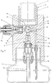
- the bottle dispenser has only a section reproduced container 1, which the to be dosed Absorbs liquid.
- a dosing head 3 screwed on the top a pump 4 in the form of a positive displacement pump that So for example from a pump cylinder 5 and one Piston 6 is made.
- the pump piston 6 is not one shown mark on the outside of the cylinder assigned, with the help of which the metered quantity can be read, if necessary also with appropriate aids can be preset.
- the pump 4 is with the container 1 over a total connected with 7 designated suction line, which consists of a suction hose 8 reaching to the bottom of the container 8 and there is a channel 9 arranged in the dosing head 3.
- suction line 7 At the bottom of the dosing head 3 is in the Suction line 7 uses a suction valve 10, for example from a spring loaded ball with a Ball seat is formed.
- the dosing head has a total of 11 Output line on the one in the dosing head 3 trained channel 12 and a dosing cannula 13 exists between which a pressure valve 14 is arranged is inserted into the dosing head 3 from one side is.
- the pressure valve also has a spring-loaded Ball and a corresponding ball seat.
- the dosing head 3 there is a parallel to the suction line 7 extending return line 15 arranged, the again from a channel 16 within the dosing head and - in the embodiment shown - from one to this subsequent hose 17 is formed, which to Bottom of the container 1 is enough.
- the suction line 7, the Pressure line 11 and the return line 15 are in one Center 18 merged, which in the suction line 7th lies within the dosing head 3.
- In the center is 18 the chick of a three-way valve 19 with the paths 20, 21, 22 used.
- the three-way valve 19 is located in FIG. 1 in the operating position. In this position Upward movement of the piston 6 liquid from the container 1 via the suction line 7, the paths 22 and 20 of the Three-way cock sucked into cylinder 4.
- the total flow resistance (including spring force of the suction valve is smaller than that of the return line). In this position, the three-way valve is at a change of the container 1 also through the system Return line 15 vented.
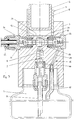
- the embodiment according to FIG. 2 differs from 1 in that in the return line 15th likewise a pressure valve 23 is inserted. Both that Pressure valve 23 in the return line 15, as well Suction valve 10 in the suction line 7 are from below the dosing head 3 attached. The three-way valve 19 is in shown the return position.
Applications Claiming Priority (2)
| Application Number | Priority Date | Filing Date | Title |
|---|---|---|---|
| DE19754558A DE19754558B4 (de) | 1997-12-09 | 1997-12-09 | Flaschendosierer |
| DE19754558 | 1997-12-09 |
Publications (3)
| Publication Number | Publication Date |
|---|---|
| EP0922939A2 true EP0922939A2 (fr) | 1999-06-16 |
| EP0922939A3 EP0922939A3 (fr) | 2000-09-13 |
| EP0922939B1 EP0922939B1 (fr) | 2003-07-02 |
Family
ID=7851223
Family Applications (1)
| Application Number | Title | Priority Date | Filing Date |
|---|---|---|---|
| EP98123222A Expired - Lifetime EP0922939B1 (fr) | 1997-12-09 | 1998-12-07 | Dispositif de dosage pour bouteilles |
Country Status (4)
| Country | Link |
|---|---|
| EP (1) | EP0922939B1 (fr) |
| AT (1) | ATE244397T1 (fr) |
| DE (2) | DE19754558B4 (fr) |
| ES (1) | ES2199401T3 (fr) |
Cited By (5)
| Publication number | Priority date | Publication date | Assignee | Title |
|---|---|---|---|---|
| US6221902B1 (en) | 1998-05-12 | 2001-04-24 | American Home Products Corporation | Biphenyl sulfonyl aryl carboxylic acids useful in the treatment of insulin resistance and hyperglycemia |
| DE10059217A1 (de) * | 2000-11-29 | 2002-06-13 | Brand Gmbh & Co Kg | Verfahen zum Abgeben von Flüssigkeitsvolumina sowie Abgabevorrichtung dafür |
| WO2004018977A1 (fr) * | 2002-07-31 | 2004-03-04 | Poulten & Graf Gmbh | Distributeur de liquide, systeme modulaire de canule de distribution pour ce distributeur et canule de distribution |
| WO2010122568A1 (fr) * | 2009-04-22 | 2010-10-28 | Chirag Narendrabhai Shah | Distributeur pour goulot de bouteille doté d'un mécanisme de recirculation et d'évacuation |
| DE102015117637A1 (de) * | 2015-10-16 | 2017-04-20 | Endress+Hauser Conducta Gmbh+Co. Kg | Verfahren zur Verbesserung einer Messgenauigkeit eines nasschemischen Analysegerätes bei einer Bestimmung eines Parameters einer zu analysierenden Flüssigkeit |
Families Citing this family (1)
| Publication number | Priority date | Publication date | Assignee | Title |
|---|---|---|---|---|
| DE19861333B4 (de) * | 1998-02-23 | 2005-08-18 | Poulten & Graf Gmbh | Ausgabekanüle für einen Dosier-Dispenser und Fluidabgabevorrichtung |
Citations (4)
| Publication number | Priority date | Publication date | Assignee | Title |
|---|---|---|---|---|
| GB386410A (en) * | 1931-12-09 | 1933-01-19 | Charles Spaeth | Improvements in apparatus for delivering measured quantities of fluid |
| US5141137A (en) * | 1988-11-15 | 1992-08-25 | Walter Graf U. Co. Gmbh & Co. | Volumetric device with reciprocating piston to deliver defined quantities of liquids |
| DE19615661A1 (de) * | 1996-04-19 | 1997-10-23 | Hirschmann Laborgeraete Gmbh | Flaschendosierer |
| DE29710012U1 (de) * | 1996-06-24 | 1997-12-04 | Industrieplanung Theodor Fesse | Flüssigkeitsdipsenser, Förder- oder Dosierzylindervorrichtung, insbesondere für einen Flüssigkeitsdispenser und Formwerkzeug zur Herstellung eines Flüssigkeitsdispensers |
Family Cites Families (5)
| Publication number | Priority date | Publication date | Assignee | Title |
|---|---|---|---|---|
| DE3800667A1 (de) * | 1988-01-13 | 1989-07-27 | Brand Rudolf Gmbh & Co | Vorrichtung zum messen und/oder abgeben von fluessigkeitsvolumina, insbesondere dispenser, buerette oder dergleichen |
| DE4143693B4 (de) * | 1991-11-13 | 2006-10-26 | Vitlab Gmbh | Flaschendispenser |
| DE9316886U1 (de) * | 1993-11-04 | 1994-01-13 | Brand Gmbh & Co | Dispenser |
| DE4344320C2 (de) * | 1993-12-23 | 2003-09-18 | Witeg Labortechnik Gmbh | Vorrichtung zur dosierten Ausgabe von Flüssigkeitsmengen |
| DE19536258C5 (de) * | 1995-09-28 | 2011-07-14 | VITLAB GmbH, 64342 | Flaschendispenser |
-
1997
- 1997-12-09 DE DE19754558A patent/DE19754558B4/de not_active Expired - Lifetime
-
1998
- 1998-12-07 EP EP98123222A patent/EP0922939B1/fr not_active Expired - Lifetime
- 1998-12-07 AT AT98123222T patent/ATE244397T1/de not_active IP Right Cessation
- 1998-12-07 ES ES98123222T patent/ES2199401T3/es not_active Expired - Lifetime
- 1998-12-07 DE DE59808893T patent/DE59808893D1/de not_active Expired - Lifetime
Patent Citations (4)
| Publication number | Priority date | Publication date | Assignee | Title |
|---|---|---|---|---|
| GB386410A (en) * | 1931-12-09 | 1933-01-19 | Charles Spaeth | Improvements in apparatus for delivering measured quantities of fluid |
| US5141137A (en) * | 1988-11-15 | 1992-08-25 | Walter Graf U. Co. Gmbh & Co. | Volumetric device with reciprocating piston to deliver defined quantities of liquids |
| DE19615661A1 (de) * | 1996-04-19 | 1997-10-23 | Hirschmann Laborgeraete Gmbh | Flaschendosierer |
| DE29710012U1 (de) * | 1996-06-24 | 1997-12-04 | Industrieplanung Theodor Fesse | Flüssigkeitsdipsenser, Förder- oder Dosierzylindervorrichtung, insbesondere für einen Flüssigkeitsdispenser und Formwerkzeug zur Herstellung eines Flüssigkeitsdispensers |
Cited By (8)
| Publication number | Priority date | Publication date | Assignee | Title |
|---|---|---|---|---|
| US6221902B1 (en) | 1998-05-12 | 2001-04-24 | American Home Products Corporation | Biphenyl sulfonyl aryl carboxylic acids useful in the treatment of insulin resistance and hyperglycemia |
| DE10059217A1 (de) * | 2000-11-29 | 2002-06-13 | Brand Gmbh & Co Kg | Verfahen zum Abgeben von Flüssigkeitsvolumina sowie Abgabevorrichtung dafür |
| DE10059217B4 (de) * | 2000-11-29 | 2005-05-25 | Brand Gmbh + Co Kg | Verfahen zum Abgeben von Flüssigkeitsvolumina sowie Abgabevorrichtung dafür |
| DE10059217C5 (de) * | 2000-11-29 | 2010-10-14 | Brand Gmbh + Co Kg | Verfahen zum Abgeben von Flüssigkeitsvolumina sowie Abgabevorrichtung dafür |
| WO2004018977A1 (fr) * | 2002-07-31 | 2004-03-04 | Poulten & Graf Gmbh | Distributeur de liquide, systeme modulaire de canule de distribution pour ce distributeur et canule de distribution |
| US7198176B2 (en) | 2002-07-31 | 2007-04-03 | Poulten & Graf Gmbh | Liquid dispenser, hollow dispensing needle kit system for said liquid dispenser, and hollow dispensing needle |
| WO2010122568A1 (fr) * | 2009-04-22 | 2010-10-28 | Chirag Narendrabhai Shah | Distributeur pour goulot de bouteille doté d'un mécanisme de recirculation et d'évacuation |
| DE102015117637A1 (de) * | 2015-10-16 | 2017-04-20 | Endress+Hauser Conducta Gmbh+Co. Kg | Verfahren zur Verbesserung einer Messgenauigkeit eines nasschemischen Analysegerätes bei einer Bestimmung eines Parameters einer zu analysierenden Flüssigkeit |
Also Published As
| Publication number | Publication date |
|---|---|
| DE59808893D1 (de) | 2003-08-07 |
| DE19754558A1 (de) | 1999-06-17 |
| ATE244397T1 (de) | 2003-07-15 |
| DE19754558B4 (de) | 2005-07-07 |
| EP0922939A3 (fr) | 2000-09-13 |
| EP0922939B1 (fr) | 2003-07-02 |
| ES2199401T3 (es) | 2004-02-16 |
Similar Documents
| Publication | Publication Date | Title |
|---|---|---|
| DE2701658C2 (de) | Automatische Umschaltvorrichtung für Anlagen zur Abgabe von zähflüssigen Flüssigkeiten | |
| DE4041135C2 (de) | Ansaug- oder Ausgabeventil für eine Dosier- und Spraypumpe zur Abgabe flüssiger, niederviskoser und pastöser Stoffe | |
| DE3837704C2 (de) | Pastenspender | |
| DE3050957C2 (fr) | ||
| DE2943074C2 (de) | In einen Behälterhals einsetzbarer Flüssigkeitszerstäuber | |
| EP0738543B1 (fr) | Pompe de distribution en matière plastique pour matière pâteuse | |
| DE3631149C2 (fr) | ||
| DE4212413C2 (de) | Dosierpumpe aus Kunststoff für hochviskose, insbesondere pastenartige Medien | |
| DE3347629C2 (fr) | ||
| DE10110888A1 (de) | Dosierpumpenspender mit wenigstens zwei Dosierpumpen | |
| WO2009109370A1 (fr) | Dispositif de dosage | |
| EP0922939B1 (fr) | Dispositif de dosage pour bouteilles | |
| DE202011102452U1 (de) | Dosierspender | |
| DE2250887A1 (de) | Weinende puppe | |
| DE2808898A1 (de) | Dosiervorrichtung fuer fluessigkeiten, insbesondere fluessige wasch- oder pflegemittel bei wasch- oder geschirrspuelmaschinen | |
| DE3124944A1 (de) | "hochdruckreiniger" | |
| DE202018100952U1 (de) | Druckmechanismus eines Nahrungsmittel-Flüssigkeitsbehältnisses | |
| WO2001026821A1 (fr) | Bouteille pourvue d'une pompe | |
| DE60003280T2 (de) | Mehrkolben-spender mit ratschen-mechanismus | |
| EP0418926B1 (fr) | Dispositif de distribution de doses de liquides à partir d'un réservoir de stockage | |
| DE4312015A1 (de) | Vorrichtung zum Dosieren und Abfüllen von dickflüssigen oder pastösen Produkten, insbesondere Nahrungsmittel, vornehmlich Margarine oder dergleichen | |
| DE2656238B2 (de) | Dampfbügeleisen | |
| EP1308658A2 (fr) | Robinet à voies multiples | |
| DE54961C (de) | Spritze mit Flüssigkeitsbehälter | |
| DE278204C (fr) |
Legal Events
| Date | Code | Title | Description |
|---|---|---|---|
| PUAI | Public reference made under article 153(3) epc to a published international application that has entered the european phase |
Free format text: ORIGINAL CODE: 0009012 |
|
| AK | Designated contracting states |
Kind code of ref document: A2 Designated state(s): AT BE CH DE ES FI FR GB IT LI LU NL SE |
|
| AX | Request for extension of the european patent |
Free format text: AL;LT;LV;MK;RO;SI |
|
| PUAL | Search report despatched |
Free format text: ORIGINAL CODE: 0009013 |
|
| AK | Designated contracting states |
Kind code of ref document: A3 Designated state(s): AT BE CH CY DE DK ES FI FR GB GR IE IT LI LU MC NL PT SE |
|
| AX | Request for extension of the european patent |
Free format text: AL;LT;LV;MK;RO;SI |
|
| AKX | Designation fees paid | ||
| REG | Reference to a national code |
Ref country code: DE Ref legal event code: 8566 |
|
| 17P | Request for examination filed |
Effective date: 20010109 |
|
| RBV | Designated contracting states (corrected) |
Designated state(s): AT BE CH DE ES FI FR GB IT LI LU NL SE |
|
| GRAH | Despatch of communication of intention to grant a patent |
Free format text: ORIGINAL CODE: EPIDOS IGRA |
|
| GRAH | Despatch of communication of intention to grant a patent |
Free format text: ORIGINAL CODE: EPIDOS IGRA |
|
| GRAA | (expected) grant |
Free format text: ORIGINAL CODE: 0009210 |
|
| AK | Designated contracting states |
Designated state(s): AT BE CH DE ES FI FR GB IT LI LU NL SE |
|
| REG | Reference to a national code |
Ref country code: GB Ref legal event code: FG4D Free format text: NOT ENGLISH |
|
| RIN1 | Information on inventor provided before grant (corrected) |
Inventor name: RIEKER, HANS Inventor name: BIGUS, HANS-JUERGEN DR. RER. NAT. |
|
| REG | Reference to a national code |
Ref country code: CH Ref legal event code: EP |
|
| REF | Corresponds to: |
Ref document number: 59808893 Country of ref document: DE Date of ref document: 20030807 Kind code of ref document: P |
|
| REG | Reference to a national code |
Ref country code: CH Ref legal event code: NV Representative=s name: TROESCH SCHEIDEGGER WERNER AG |
|
| REG | Reference to a national code |
Ref country code: SE Ref legal event code: TRGR |
|
| GBT | Gb: translation of ep patent filed (gb section 77(6)(a)/1977) | ||
| PGFP | Annual fee paid to national office [announced via postgrant information from national office to epo] |
Ref country code: ES Payment date: 20031103 Year of fee payment: 6 |
|
| PGFP | Annual fee paid to national office [announced via postgrant information from national office to epo] |
Ref country code: BE Payment date: 20031104 Year of fee payment: 6 |
|
| PGFP | Annual fee paid to national office [announced via postgrant information from national office to epo] |
Ref country code: LU Payment date: 20031126 Year of fee payment: 6 |
|
| PGFP | Annual fee paid to national office [announced via postgrant information from national office to epo] |
Ref country code: AT Payment date: 20031212 Year of fee payment: 6 |
|
| PGFP | Annual fee paid to national office [announced via postgrant information from national office to epo] |
Ref country code: SE Payment date: 20031216 Year of fee payment: 6 |
|
| PGFP | Annual fee paid to national office [announced via postgrant information from national office to epo] |
Ref country code: NL Payment date: 20031223 Year of fee payment: 6 |
|
| REG | Reference to a national code |
Ref country code: ES Ref legal event code: FG2A Ref document number: 2199401 Country of ref document: ES Kind code of ref document: T3 |
|
| ET | Fr: translation filed | ||
| PLBQ | Unpublished change to opponent data |
Free format text: ORIGINAL CODE: EPIDOS OPPO |
|
| PLBI | Opposition filed |
Free format text: ORIGINAL CODE: 0009260 |
|
| PLAX | Notice of opposition and request to file observation + time limit sent |
Free format text: ORIGINAL CODE: EPIDOSNOBS2 |
|
| 26 | Opposition filed |
Opponent name: POULTEN & GRAF GMBH Effective date: 20040402 |
|
| PLBB | Reply of patent proprietor to notice(s) of opposition received |
Free format text: ORIGINAL CODE: EPIDOSNOBS3 |
|
| NLR1 | Nl: opposition has been filed with the epo |
Opponent name: POULTEN & GRAF GMBH |
|
| PG25 | Lapsed in a contracting state [announced via postgrant information from national office to epo] |
Ref country code: LU Free format text: LAPSE BECAUSE OF NON-PAYMENT OF DUE FEES Effective date: 20041207 Ref country code: AT Free format text: LAPSE BECAUSE OF NON-PAYMENT OF DUE FEES Effective date: 20041207 |
|
| PG25 | Lapsed in a contracting state [announced via postgrant information from national office to epo] |
Ref country code: SE Free format text: LAPSE BECAUSE OF NON-PAYMENT OF DUE FEES Effective date: 20041208 |
|
| PG25 | Lapsed in a contracting state [announced via postgrant information from national office to epo] |
Ref country code: ES Free format text: LAPSE BECAUSE OF NON-PAYMENT OF DUE FEES Effective date: 20041209 |
|
| PG25 | Lapsed in a contracting state [announced via postgrant information from national office to epo] |
Ref country code: BE Free format text: LAPSE BECAUSE OF NON-PAYMENT OF DUE FEES Effective date: 20041231 |
|
| BERE | Be: lapsed |
Owner name: *HIRSCHMANN LABORGERATE G.M.B.H. & CO. K.G. Effective date: 20041231 |
|
| PG25 | Lapsed in a contracting state [announced via postgrant information from national office to epo] |
Ref country code: NL Free format text: LAPSE BECAUSE OF NON-PAYMENT OF DUE FEES Effective date: 20050701 |
|
| EUG | Se: european patent has lapsed | ||
| NLV4 | Nl: lapsed or anulled due to non-payment of the annual fee |
Effective date: 20050701 |
|
| REG | Reference to a national code |
Ref country code: ES Ref legal event code: FD2A Effective date: 20041209 |
|
| BERE | Be: lapsed |
Owner name: *HIRSCHMANN LABORGERATE G.M.B.H. & CO. K.G. Effective date: 20041231 |
|
| PLBP | Opposition withdrawn |
Free format text: ORIGINAL CODE: 0009264 |
|
| PLBD | Termination of opposition procedure: decision despatched |
Free format text: ORIGINAL CODE: EPIDOSNOPC1 |
|
| PLBM | Termination of opposition procedure: date of legal effect published |
Free format text: ORIGINAL CODE: 0009276 |
|
| STAA | Information on the status of an ep patent application or granted ep patent |
Free format text: STATUS: OPPOSITION PROCEDURE CLOSED |
|
| 27C | Opposition proceedings terminated |
Effective date: 20100109 |
|
| REG | Reference to a national code |
Ref country code: FR Ref legal event code: PLFP Year of fee payment: 18 |
|
| REG | Reference to a national code |
Ref country code: FR Ref legal event code: PLFP Year of fee payment: 19 |
|
| REG | Reference to a national code |
Ref country code: FR Ref legal event code: PLFP Year of fee payment: 20 |
|
| PGFP | Annual fee paid to national office [announced via postgrant information from national office to epo] |
Ref country code: DE Payment date: 20180516 Year of fee payment: 20 Ref country code: FI Payment date: 20180517 Year of fee payment: 20 Ref country code: CH Payment date: 20180523 Year of fee payment: 20 |
|
| PGFP | Annual fee paid to national office [announced via postgrant information from national office to epo] |
Ref country code: FR Payment date: 20180528 Year of fee payment: 20 Ref country code: IT Payment date: 20180518 Year of fee payment: 20 |
|
| PGFP | Annual fee paid to national office [announced via postgrant information from national office to epo] |
Ref country code: GB Payment date: 20180523 Year of fee payment: 20 |
|
| REG | Reference to a national code |
Ref country code: DE Ref legal event code: R071 Ref document number: 59808893 Country of ref document: DE |
|
| REG | Reference to a national code |
Ref country code: CH Ref legal event code: PL |
|
| REG | Reference to a national code |
Ref country code: GB Ref legal event code: PE20 Expiry date: 20181206 |
|
| PG25 | Lapsed in a contracting state [announced via postgrant information from national office to epo] |
Ref country code: GB Free format text: LAPSE BECAUSE OF EXPIRATION OF PROTECTION Effective date: 20181206 |