EP0922939A2 - Dispensing device for bottles - Google Patents
Dispensing device for bottles Download PDFInfo
- Publication number
- EP0922939A2 EP0922939A2 EP98123222A EP98123222A EP0922939A2 EP 0922939 A2 EP0922939 A2 EP 0922939A2 EP 98123222 A EP98123222 A EP 98123222A EP 98123222 A EP98123222 A EP 98123222A EP 0922939 A2 EP0922939 A2 EP 0922939A2
- Authority
- EP
- European Patent Office
- Prior art keywords
- line
- suction
- container
- dosing head
- return line
- Prior art date
- Legal status (The legal status is an assumption and is not a legal conclusion. Google has not performed a legal analysis and makes no representation as to the accuracy of the status listed.)
- Granted
Links
Images

Classifications
-
- G—PHYSICS
- G01—MEASURING; TESTING
- G01F—MEASURING VOLUME, VOLUME FLOW, MASS FLOW OR LIQUID LEVEL; METERING BY VOLUME
- G01F11/00—Apparatus requiring external operation adapted at each repeated and identical operation to measure and separate a predetermined volume of fluid or fluent solid material from a supply or container, without regard to weight, and to deliver it
- G01F11/02—Apparatus requiring external operation adapted at each repeated and identical operation to measure and separate a predetermined volume of fluid or fluent solid material from a supply or container, without regard to weight, and to deliver it with measuring chambers which expand or contract during measurement
- G01F11/021—Apparatus requiring external operation adapted at each repeated and identical operation to measure and separate a predetermined volume of fluid or fluent solid material from a supply or container, without regard to weight, and to deliver it with measuring chambers which expand or contract during measurement of the piston type
- G01F11/025—Apparatus requiring external operation adapted at each repeated and identical operation to measure and separate a predetermined volume of fluid or fluent solid material from a supply or container, without regard to weight, and to deliver it with measuring chambers which expand or contract during measurement of the piston type with manually operated pistons
- G01F11/028—Apparatus requiring external operation adapted at each repeated and identical operation to measure and separate a predetermined volume of fluid or fluent solid material from a supply or container, without regard to weight, and to deliver it with measuring chambers which expand or contract during measurement of the piston type with manually operated pistons the dosing device being provided with a dip tube and fitted to a container, e.g. to a bottleneck
Definitions
- the invention relates to a bottle dispenser with a the containers to be dosed containing liquid, a dosing head closing this with a pump, a suction line connecting this to the container Suction valve, a discharge line connected to the pump with pressure valve, one arranged between pump and container Return line and a switching element for the different flow paths.
- Bottle dispensers of this type are used for dispensing Liquids of any kind with different adjustable volumes.
- the container is in bottle form formed and has a container neck on which the Dosing head with the pump via a screw or ground joint is put on.
- the pump can be any Have structure. As a rule, it is a Positive displacement pump, e.g. a piston pump that manually or is electrically powered.
- the volume to be dosed is preset in this case via the piston stroke.
- the switching element is initially set so that the pump in the suction stroke by opening the suction valve the liquid from the container in the suction line sucks. After the switching element has been changed accordingly the preset volume during the pressure stroke of the Pump opening the pressure valve via the discharge line submitted. For remaining quantities in the pump back in the container, will be in another Position of the switching element during the pressure stroke of the pump Residual liquid contained in the pump chamber via the return line returned to the container.
- a compact design results in a another known version (DE 195 36 258), in which the suction line and a section of the discharge line in the are arranged substantially axially parallel in the dosing head. Both lines have this inside the dosing head Suction valve and the pressure valve on. Behind the pressure valve is the actual delivery cannula into the vertical Discharge line inserted, the vertical section the discharge line with the pressure valve at the same time forms the return line. It is made by pulling the Dispensing cannula open while dispensing cannula is inserted this through a hole with the inside of the Dosing head arranged section of the discharge line in fluidic connection.
- the invention has for its object a bottle dispenser of the structure mentioned at the beginning in a constructive, from a functional and operational point of view simplify.
- suction line, the discharge line and the return line are brought together in a center that is located in the Suction line lies between the suction valve and the pump, and that in the center is a switching element Three-way valve is arranged.
- the Switching element is located centrally on the dosing head. His education as a three-way valve is special in ergonomic terms cheap, since the user based on the switch positions alone can "read" the flow paths.
- the necessary Sealing surfaces are at a minimum, namely on the Guide surfaces of the three-way valve reduced. It acts it is cylindrical or conical surfaces that can be realized without problems liquid-tight.
- the dosing head with the three-way valve can also be used without any problems clean and replace the latter if necessary.
- the suction line, the discharge line and the return line at right angles in the center merged.
- This is also a manufacturing technology given a particularly simple solution.
- the return line can either reach the bottom of the Container run and then needs no separate Valve to be secured. Instead, the Return line, as known per se, a pressure valve have and then immediately below the dosing head flow into the container.
- a particularly simple design is characterized by this from that the suction line, the discharge line and at least a section of the return line through two in the Boreholes intersecting in the center with the three - way valve Dosing head are formed.
- the suction line and another section the return line from substantially parallel bores be formed in the dosing head so that a space-saving arrangement results in a corresponding space-saving dimensioning of the dosing head leads.
- the delivery line can and one section of the return line from one through hole passing through the dosing head, in one end of which the pressure valve of the discharge line and in the other end the pressure valve of the return line is inserted. So there are only two in the dosing head Through holes for the suction line on the one hand and the pressure line and a section of the return line on the other hand, to provide the manufacturing technology can be realized particularly easily.
- the other Section of the return line is then called the tap hole parallel or essentially parallel to the suction line guided.
- the dosing head can also be used in this way easily manufactured as an injection molded part.
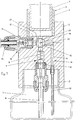
- the bottle dispenser has only a section reproduced container 1, which the to be dosed Absorbs liquid.
- a dosing head 3 screwed on the top a pump 4 in the form of a positive displacement pump that So for example from a pump cylinder 5 and one Piston 6 is made.
- the pump piston 6 is not one shown mark on the outside of the cylinder assigned, with the help of which the metered quantity can be read, if necessary also with appropriate aids can be preset.
- the pump 4 is with the container 1 over a total connected with 7 designated suction line, which consists of a suction hose 8 reaching to the bottom of the container 8 and there is a channel 9 arranged in the dosing head 3.
- suction line 7 At the bottom of the dosing head 3 is in the Suction line 7 uses a suction valve 10, for example from a spring loaded ball with a Ball seat is formed.
- the dosing head has a total of 11 Output line on the one in the dosing head 3 trained channel 12 and a dosing cannula 13 exists between which a pressure valve 14 is arranged is inserted into the dosing head 3 from one side is.
- the pressure valve also has a spring-loaded Ball and a corresponding ball seat.
- the dosing head 3 there is a parallel to the suction line 7 extending return line 15 arranged, the again from a channel 16 within the dosing head and - in the embodiment shown - from one to this subsequent hose 17 is formed, which to Bottom of the container 1 is enough.
- the suction line 7, the Pressure line 11 and the return line 15 are in one Center 18 merged, which in the suction line 7th lies within the dosing head 3.
- In the center is 18 the chick of a three-way valve 19 with the paths 20, 21, 22 used.
- the three-way valve 19 is located in FIG. 1 in the operating position. In this position Upward movement of the piston 6 liquid from the container 1 via the suction line 7, the paths 22 and 20 of the Three-way cock sucked into cylinder 4.
- the total flow resistance (including spring force of the suction valve is smaller than that of the return line). In this position, the three-way valve is at a change of the container 1 also through the system Return line 15 vented.
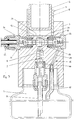
- the embodiment according to FIG. 2 differs from 1 in that in the return line 15th likewise a pressure valve 23 is inserted. Both that Pressure valve 23 in the return line 15, as well Suction valve 10 in the suction line 7 are from below the dosing head 3 attached. The three-way valve 19 is in shown the return position.
Abstract
Description
Die Erfindung betrifft einen Flaschendosierer mit einem die zu dosierende Flüssigkeit enthaltenden Behälter, einem diesen verschließenden Dosierkopf mit einer Pumpe, einer diese mit dem Behälter verbindenden Saugleitung mit Saugventil, einer mit der Pumpe verbundenen Abgabeleitung mit Druckventil, einer zwischen Pumpe und Behälter angeordneten Rücklaufleitung und einem Schaltorgan für die verschiedenen Strömungswege.The invention relates to a bottle dispenser with a the containers to be dosed containing liquid, a dosing head closing this with a pump, a suction line connecting this to the container Suction valve, a discharge line connected to the pump with pressure valve, one arranged between pump and container Return line and a switching element for the different flow paths.
Flaschendosierer dieser Art dienen zum Dosieren von Flüssigkeiten beliebiger Art mit unterschiedlichen, einstellbaren Volumina. Der Behälter ist in Flaschenform ausgebildet und weist einen Behälterhals auf, auf den der Dosierkopf mit der Pumpe über eine Schraub- oder Schliffverbindung aufgesetzt ist. Die Pumpe kann beliebigen Aufbau aufweisen. In der Regel handelt es sich um eine Verdrängerpumpe, z.B. eine Kolbenpumpe, die manuell oder elektrisch angetrieben ist. Das zu dosierende Volumen wird in diesem Fall über den Kolbenhub voreingestellt. Für den Betrieb wird das Schaltorgan zunächst so eingestellt, daß die Pumpe im Saughub durch Öffnen des Saugventils in der Saugleitung die Flüssigkeit aus dem Behälter ansaugt. Nach entsprechendem Umstellen des Schaltorgans wird das voreingestellte Volumen beim Druckhub der Pumpe unter Öffnen des Druckventils über die Abgabeleitung abgegeben. Um in der Pumpe verbleibende Restmengen in den Behälter zurückzuführen, wird in einer weiteren Stellung des Schaltorgans beim Druckhub der Pumpe die im Pumpenraum enthaltene Restflüssigkeit über die Rücklaufleitung wieder in den Behälter abgegeben.Bottle dispensers of this type are used for dispensing Liquids of any kind with different adjustable volumes. The container is in bottle form formed and has a container neck on which the Dosing head with the pump via a screw or ground joint is put on. The pump can be any Have structure. As a rule, it is a Positive displacement pump, e.g. a piston pump that manually or is electrically powered. The volume to be dosed is preset in this case via the piston stroke. For operation, the switching element is initially set so that the pump in the suction stroke by opening the suction valve the liquid from the container in the suction line sucks. After the switching element has been changed accordingly the preset volume during the pressure stroke of the Pump opening the pressure valve via the discharge line submitted. For remaining quantities in the pump back in the container, will be in another Position of the switching element during the pressure stroke of the pump Residual liquid contained in the pump chamber via the return line returned to the container.
Bekannte Ausführungen solcher Flaschendosierer (DE 38 00 667, DE 43 44 320) weisen als Schaltorgan relativ komplizierte Ventilwellen auf, die den Dosierkopf durchsetzen und an ihrem einen außenliegenden Ende ein Betätigungsorgan aufweisen. In der Ventilwelle sind in relativ verwickelter Anordnung Kanäle eingebracht, die mit weiteren Kanälen im Dosierkopf die notwendigen drei Strömungswege (Ansaugen, Abgeben und Rückführen) bilden. Daneben sind dann innerhalb der die Saugleitung und die Abgabeleitung bildenden Kanäle des Dosierkopfs das Saugventil bzw. das Druckventil angeordnet. Diese bekannten Ausführungen sind konstruktiv aufwendig, platzraubend und funktionsanfällig.Known designs of such bottle dispensers (DE 38 00 667, DE 43 44 320) have relatively complicated switching elements Valve shafts that penetrate the dosing head and an actuator at one outer end thereof exhibit. In the valve shaft are relatively involved Arrangement channels introduced that with further Channels in the dosing head the necessary three flow paths (Suction, discharge and return) form. Are next to it then within the the suction line and the discharge line forming channels of the dosing head, the suction valve or Pressure valve arranged. These known designs are structurally complex, space-consuming and functional.
Bei einer anderen bekannten Bauweise (DE 0 542 241, EP 0 652 421) ist die Rücklaufleitung hinter dem Druckventil von der Abgabeleitung abgezweigt. Dies führt zu einer hahnartigen Konstruktion, die weitgehend außerhalb des eigentlichen Dosierkopfs liegt und deshalb einen hohen Platzbedarf aufweist. Auch hier ist der konstruktive Bauaufwand relativ groß. In another known construction (DE 0 542 241, EP 0 652 421) is the return line behind the pressure valve branched off from the delivery line. This leads to a cock-like construction, which is largely outside the actual dosing head and is therefore high Has space requirements. Here too is the constructive one Construction effort relatively large.
Eine kompakte Bauweise ergibt sich demgegenüber bei einer weiteren bekannten Ausführung (DE 195 36 258), bei der die Saugleitung und ein Abschnitt der Abgabeleitung im wesentlichen achsparallel im Dosierkopf angeordnet sind. Beide Leitungen weisen innerhalb des Dosierkopfs das Saugventil und das Druckventil auf. Hinter dem Druckventil ist senkrecht die eigentliche Abgabekanüle in die Abgabeleitung eingeschoben, wobei der senkrechte Abschnitt der Abgabeleitung mit dem Druckventil zugleich die Rücklaufleitung bildet. Sie wird durch Ziehen der Abgabekanüle geöffnet, während bei eingeschobener Abgabekanüle diese über eine Bohrung mit dem innerhalb des Dosierkopfs angeordneten Abschnitt der Abgabeleitung in strömungstechnischer Verbindung steht. Bei einer anderen Ausführung (DE 196 15 661) ist der Dosierkopf zweiteilig ausgebildet und der eine Teil mit der Pumpe in dem anderen Teil um eine senkrechte Achse drehbar gelagert. In den einander anliegenden Stirnseiten beider Teile ist in der Drehachse je ein Abschnitt der Saugleitung mit dem Saugventil und in dem pumpenseitigen, drehbaren Teil ein weiterer Kanal mit dem Druckventil angeordnet, der je nach Drehlage des pumpenseitigen Teils mit der Abgabeleitung oder der Rücklaufleitung in Flucht gebracht werden kann. Diese Ausführung ist zwar konstruktiv einfach, jedoch ist die Abdichtung der alle in einer Ebene mündenden Kanäle gegeneinander aufwendig und funktionsanfällig.In contrast, a compact design results in a another known version (DE 195 36 258), in which the suction line and a section of the discharge line in the are arranged substantially axially parallel in the dosing head. Both lines have this inside the dosing head Suction valve and the pressure valve on. Behind the pressure valve is the actual delivery cannula into the vertical Discharge line inserted, the vertical section the discharge line with the pressure valve at the same time forms the return line. It is made by pulling the Dispensing cannula open while dispensing cannula is inserted this through a hole with the inside of the Dosing head arranged section of the discharge line in fluidic connection. Another one Version (DE 196 15 661) the dosing head is in two parts trained and one part with the pump in the other Part rotatably mounted about a vertical axis. In the abutting end faces of both parts is in a section of the suction line with the Suction valve and in the pump-side, rotatable part another channel with the pressure valve arranged, each according to the rotational position of the part on the pump side with the discharge line or the return line are brought into flight can. This version is structurally simple, however, the seal is all opening into one plane Channels against each other complex and functional.
Der Erfindung liegt die Aufgabe zugrunde, einen Flaschendosierer des eingangs genannten Aufbaus in konstruktiver, funktioneller und bedienungstechnischer Hinsicht zu vereinfachen.The invention has for its object a bottle dispenser of the structure mentioned at the beginning in a constructive, from a functional and operational point of view simplify.
Diese Aufgabe wird erfindungsgemäß dadurch gelöst, daß die Saugleitung, die Abgabeleitung und die Rücklaufleitung in einem Zentrum zusammengeführt sind, das in der Saugleitung zwischen dem Saugventil und der Pumpe liegt, und daß in dem Zentrum ein das Schaltorgan bildender Dreiwegehahn angeordnet ist.This object is achieved in that the suction line, the discharge line and the return line are brought together in a center that is located in the Suction line lies between the suction valve and the pump, and that in the center is a switching element Three-way valve is arranged.
Gegenüber den bekannten Flaschendosierern ergibt sich zunächst eine äußerst kompakte Bauweise, da sämtliche Strömungswege innerhalb des Dosierkopfs verlaufen und in dem Zentrum mit dem Schaltorgan zusammengeführt sind. Dabei lassen sich die die verschiedenen Strömungswege bildenden Leitungen in konstruktiv übersichtlicher und fertigungstechnisch einfache Form realisieren. Das Schaltorgan sitzt zentral am Dosierkopf. Seine Ausbildung als Dreiwegehahn ist in ergonomischer Hinsicht besonders günstig, da der Benutzer schon allein anhand der Schaltstellungen die Strömungswege "ablesen" kann. Die notwendigen Dichtflächen sind auf ein Minimum, nämlich auf die Führungsflachen des Dreiwegehahns reduziert. Dabei handelt es sich um zylindrische oder konische Flächen, die problemlos flüssigkeitsdicht zu verwirklichen sind. Ebenso problemlos läßt sich der Dosierkopf mit dem Dreiwegehahn reinigen und letzterer notwendigenfalls auswechseln.Compared to the well-known bottle dispensers First of all an extremely compact design, because all Flow paths run inside the dosing head and in the center are merged with the switching element. Here, the different flow paths forming lines in a structurally clear and realize simple form in terms of production technology. The Switching element is located centrally on the dosing head. His education as a three-way valve is special in ergonomic terms cheap, since the user based on the switch positions alone can "read" the flow paths. The necessary Sealing surfaces are at a minimum, namely on the Guide surfaces of the three-way valve reduced. It acts it is cylindrical or conical surfaces that can be realized without problems liquid-tight. The dosing head with the three-way valve can also be used without any problems clean and replace the latter if necessary.
Vorzugsweise sind die Saugleitung, die Abgabeleitung und die Rücklaufleitung unter rechten Winkeln im Zentrum zusammengeführt. Auch hierdurch ist eine fertigungstechnisch besonders einfache Lösung gegeben.Preferably, the suction line, the discharge line and the return line at right angles in the center merged. This is also a manufacturing technology given a particularly simple solution.
Die Rücklaufleitung kann entweder bis zum Boden des Behälters verlaufen und braucht dann durch kein gesondertes Ventil abgesichert zu sein. Stattdessen kann die Rücklaufleitung, wie an sich bekannt, ein Druckventil aufweisen und dann unmittelbar unterhalb des Dosierkopfs in den Behälter münden.The return line can either reach the bottom of the Container run and then needs no separate Valve to be secured. Instead, the Return line, as known per se, a pressure valve have and then immediately below the dosing head flow into the container.
Eine besonders einfache Ausführung zeichnet sich dadurch aus, daß die Saugleitung, die Abgabeleitung und zumindest ein Abschnitt der Rücklaufleitung durch zwei sich im Zentrum mit dem Dreiwegehahn kreuzende Bohrungen in dem Dosierkopf gebildet sind.A particularly simple design is characterized by this from that the suction line, the discharge line and at least a section of the return line through two in the Boreholes intersecting in the center with the three - way valve Dosing head are formed.
Dabei können die Saugleitung und ein weiterer Abschnitt der Rücklaufleitung von im wesentlichen parallelen Bohrungen im Dosierkopf gebildet sein, so daß sich eine platzsparende Anordnung ergibt, die zu einer entsprechend raumgünstigen Dimensionierung des Dosierkopfs führt.The suction line and another section the return line from substantially parallel bores be formed in the dosing head so that a space-saving arrangement results in a corresponding space-saving dimensioning of the dosing head leads.
In weiterhin vorteilhafter Ausführung kann die Abgabeleitung und der eine Abschnitt der Rücklaufleitung von einer den Dosierkopf querenden Durchgangsbohrung gebildet sein, in deren eines Ende das Druckventil der Abgabeleitung und in deren anderes Ende das Druckventil der Rücklaufleitung eingesetzt ist. Im Dosierkopf sind also lediglich zwei Durchgangsbohrungen für die Saugleitung einerseits und die Druckleitung sowie den einen Abschnitt der Rücklaufleitung andererseits vorzusehen, die sich fertigungstechnisch besonders einfach verwirklichen lassen. Der weitere Abschnitt der Rücklaufleitung wird dann als Stichbohrung parallel oder im wesentlichen parallel zur Saugleitung geführt. Der Dosierkopf laßt sich auf diese Weise auch problemlos als Spritzgußteil herstellen.In a further advantageous embodiment, the delivery line can and one section of the return line from one through hole passing through the dosing head, in one end of which the pressure valve of the discharge line and in the other end the pressure valve of the return line is inserted. So there are only two in the dosing head Through holes for the suction line on the one hand and the pressure line and a section of the return line on the other hand, to provide the manufacturing technology can be realized particularly easily. The other Section of the return line is then called the tap hole parallel or essentially parallel to the suction line guided. The dosing head can also be used in this way easily manufactured as an injection molded part.
Eine weiterhin in fertigungstechnischer Hinsicht einfache Ausführung ergibt sich dann, wenn das Saugventil an der dem Behälter zugekehrten Unterseite des Dosierkopfs angesetzt ist. In gleicher Weise kann auch das Druckventil in der Rücklaufleitung angeordnet sein, so daß sich auch die Ventile leicht reinigen, ausbauen und gegebenenfalls austauschen lassen.A still simple in terms of manufacturing technology Execution occurs when the suction valve on the bottom of the dosing head facing the container is scheduled. In the same way, the pressure valve be arranged in the return line so that also clean the valves easily, remove and if necessary exchange.
Nachstehend ist die Erfindung anhand mehrerer in der Zeichnung dargestellter Ausführungsformen beschrieben. In den Figuren 1 bis 3 ist je eine Ausführungsform im Axialschnitt gezeigt.The invention is based on several in the Described drawing of illustrated embodiments. In Figures 1 to 3 is an embodiment in axial section shown.
Der Flaschendosierer weist einen nur ausschnittsweise
wiedergegebenen Behälter 1 auf, der die zu dosierende
Flüssigkeit aufnimmt. Auf den Hals 2 des Behälters ist
ein Dosierkopf 3 aufgeschraubt, der an seiner Oberseite
eine Pumpe 4 in Form einer Verdrängerpumpe aufnimmt, die
also beispielsweise aus einem Pumpenzylinder 5 und einem
Kolben 6 besteht. Dem Pumpenkolben 6 ist eine nicht
gezeigte Markierung an der Außenseite des Zylinders
zugeordnet, mit deren Hilfe die Dosiermenge abgelesen,
gegebenenfalls mit entsprechenden Hilfsmitteln auch
voreingestellt werden kann.The bottle dispenser has only a section
reproduced
Die Pumpe 4 ist mit dem Behälter 1 über eine insgesamt
mit 7 bezeichnete Saugleitung verbunden, die aus einem
bis auf den Boden des Behälters reichenden Saugschlauch 8
und einer in dem Dosierkopf 3 angeordneten Kanal 9 besteht.
An der Unterseite des Dosierkopfs 3 ist in die
Saugleitung 7 ein Saugventil 10 eingesetzt, das beispielsweise
von einer federbelasteten Kugel mit einem
Kugelsitz gebildet ist.The
Ferner weist der Dosierkopf eine insgesamt mit 11 bezeichnete
Abgabeleitung auf, die aus einem im Dosierkopf
3 ausgebildeten Kanal 12 und einer Dosierkanüle 13
besteht, zwischen denen ein Druckventil 14 angeordnet
ist, das von einer Seite her in den Dosierkopf 3 eingesetzt
ist. Auch das Druckventil weist eine federbelastete
Kugel und einen entsprechenden Kugelsitz auf.Furthermore, the dosing head has a total of 11
Output line on the one in the
Schließlich ist im Dosierkopf 3 eine parallel zur Saugleitung
7 verlaufende Rückführleitung 15 angeordnet, die
wiederum aus einem Kanal 16 innerhalb des Dosierkopfs und
-beim gezeigten Ausführungsbeispiel- aus einem an diese
anschließenden Schlauch 17 gebildet ist, der bis zum
Boden des Behälters 1 reicht. Die Saugleitung 7, die
Druckleitung 11 und die Rückführleitung 15 sind in einem
Zentrum 18 zusammengeführt, das in der Saugleitung 7
innerhalb des Dosierkopfs 3 liegt. In das Zentrum 18 ist
das Küken eines Dreiwegehahns 19 mit den Wegen 20, 21, 22
eingesetzt. In Fig. 1 befindet sich der Dreiwegehahn 19
in der Betriebsstellung. In dieser Stellung wird bei
Aufwärtsbewegung des Kolbens 6 Flüssigkeit aus dem Behälter
1 über die Saugleitung 7, die Wege 22 und 20 des
Dreiwegehahns in den Zylinder 4 angesaugt. Dabei öffnet
das Saugventil 10, während sich das Druckventil 14 in
Schließstellung befindet. Beim anschließenden Druckhub
schließt das Saugventil 7 und wird die Flüssigkeit in der
gewünschten Menge über die Wege 20, 21 bei geöffnetem
Druckventil 14 und geschlossenem Saugventil 10 in die
Abgabekanüle 13 der Abgabeleitung 11 ausgestoßen. Soll
die Restflüssigkeit aus der pumpe 4 in den Behälter 1
zurückgeführt werden, wird der Dreiwegehahn 19 um 180°
gedreht, so daß beim Druckhub der Pumpe 4 die Flüssigkeit
über die Wege 22, 21 und die Rücklaufleitung 16 in den
Behälter zurücklaufen kann. Das Ansaugen kann bei einer
um 180° gedrehten Stellung des Dreiwegehahns erfolgen. Zu
diesem Zweck ist der Querschnitt der Rücklaufleitung 15
wesentlich kleiner als der der Saugleitung 7, deren
gesamter Strömungswiderstand (einschließlich der Federkraft
des Saugventils kleiner ist als der der Rücklaufleitung).
In dieser Position des Dreiwegehahns wird bei
einem Wechsel des Behälters 1 auch das System durch die
Rücklaufleitung 15 entlüftet.Finally, in the
Die Ausführungsform gemäß Fig. 2 unterscheidet sich von
der gemäß Fig. 1 dadurch, daß in die Rücklaufleitung 15
gleichfalls ein Druckventil 23 eingesetzt ist. Sowohl das
Druckventil 23 in der Rücklaufleitung 15, als auch das
Saugventil 10 in der Saugleitung 7 sind von unten her an
den Dosierkopf 3 angesetzt. Der Dreiwegehahn 19 ist in
der Rückführstellung gezeigt.The embodiment according to FIG. 2 differs from
1 in that in the return line 15th
likewise a
Bei dem Ausführungsbeispiel gemäß Fig. 3 sind die innerhalb
des Dosierkopfs liegenden Abschnitte 12 und 24 der
Abgabeleitung bzw. der Rückführleitung 15 durch eine den
Dosierkopf 3 querende Durchgangsbohrung gebildet, die an
ihrer einen Seite durch das Druckventil 14 der Abgabeleitung
11 an der anderen Seite durch das Druckventil 23 der
Rücklaufleitung verschlossen ist. In diesem Fall ist der
weitere Abschnitt 25 der Rücklaufleitung 15 schräg innerhalb
des Dosierkopfs 3 angeordnet.3 are within
Wie aus der Zeichnung ohne weiteres ersichtlich, lassen sich bei dem Ausführungsbeispiel gemäß Fig. 3 die notwendigen Strömungswege fertigungstechnisch einfach herstellen und der gesamte Dosierkopf mit den verschiedenen Ventilen problemlos montieren.As can be seen from the drawing, leave 3 in the embodiment according to FIG Simply create flow paths in terms of production technology and the entire dosing head with the various Assemble valves easily.
Claims (9)
Applications Claiming Priority (2)
| Application Number | Priority Date | Filing Date | Title |
|---|---|---|---|
| DE19754558A DE19754558B4 (en) | 1997-12-09 | 1997-12-09 | bottle top |
| DE19754558 | 1997-12-09 |
Publications (3)
| Publication Number | Publication Date |
|---|---|
| EP0922939A2 true EP0922939A2 (en) | 1999-06-16 |
| EP0922939A3 EP0922939A3 (en) | 2000-09-13 |
| EP0922939B1 EP0922939B1 (en) | 2003-07-02 |
Family
ID=7851223
Family Applications (1)
| Application Number | Title | Priority Date | Filing Date |
|---|---|---|---|
| EP98123222A Expired - Lifetime EP0922939B1 (en) | 1997-12-09 | 1998-12-07 | Dispensing device for bottles |
Country Status (4)
| Country | Link |
|---|---|
| EP (1) | EP0922939B1 (en) |
| AT (1) | ATE244397T1 (en) |
| DE (2) | DE19754558B4 (en) |
| ES (1) | ES2199401T3 (en) |
Cited By (5)
| Publication number | Priority date | Publication date | Assignee | Title |
|---|---|---|---|---|
| US6221902B1 (en) | 1998-05-12 | 2001-04-24 | American Home Products Corporation | Biphenyl sulfonyl aryl carboxylic acids useful in the treatment of insulin resistance and hyperglycemia |
| DE10059217A1 (en) * | 2000-11-29 | 2002-06-13 | Brand Gmbh & Co Kg | Releasing prescribed volumes of liquid, e.g. pure chemical, from pressurized container comprises feeding liquid into measuring cylinder of cylinder-piston arrangement and releasing liquid on closing inlet valve |
| WO2004018977A1 (en) * | 2002-07-31 | 2004-03-04 | Poulten & Graf Gmbh | Liquid dispenser, hollow dispensing needle kit system for said liquid dispenser, and hollow dispensing needle |
| WO2010122568A1 (en) * | 2009-04-22 | 2010-10-28 | Chirag Narendrabhai Shah | Bottle top dispenser with recirculating and draining mechanism |
| DE102015117637A1 (en) * | 2015-10-16 | 2017-04-20 | Endress+Hauser Conducta Gmbh+Co. Kg | Method for improving a measuring accuracy of a wet chemical analyzer in a determination of a parameter of a liquid to be analyzed |
Families Citing this family (1)
| Publication number | Priority date | Publication date | Assignee | Title |
|---|---|---|---|---|
| DE19861333B4 (en) * | 1998-02-23 | 2005-08-18 | Poulten & Graf Gmbh | Dispensing cannula for a dispensing dispenser and fluid dispenser |
Citations (4)
| Publication number | Priority date | Publication date | Assignee | Title |
|---|---|---|---|---|
| GB386410A (en) * | 1931-12-09 | 1933-01-19 | Charles Spaeth | Improvements in apparatus for delivering measured quantities of fluid |
| US5141137A (en) * | 1988-11-15 | 1992-08-25 | Walter Graf U. Co. Gmbh & Co. | Volumetric device with reciprocating piston to deliver defined quantities of liquids |
| DE19615661A1 (en) * | 1996-04-19 | 1997-10-23 | Hirschmann Laborgeraete Gmbh | Bottle dose dispenser for sucking and delivering liquid with housing and piston-cylinder |
| DE29710012U1 (en) * | 1996-06-24 | 1997-12-04 | Industrieplanung Theodor Fesse | Liquid dispenser, conveyor or metering cylinder device, in particular for a liquid dispenser and molding tool for producing a liquid dispenser |
Family Cites Families (5)
| Publication number | Priority date | Publication date | Assignee | Title |
|---|---|---|---|---|
| DE3800667A1 (en) * | 1988-01-13 | 1989-07-27 | Brand Rudolf Gmbh & Co | Device for measuring and/or discharging liquid volumes, in particular dispenser, burette or the like |
| DE4143693B4 (en) * | 1991-11-13 | 2006-10-26 | Vitlab Gmbh | Bottle- |
| DE9316886U1 (en) * | 1993-11-04 | 1994-01-13 | Brand Gmbh & Co | Dispenser |
| DE4344320C2 (en) * | 1993-12-23 | 2003-09-18 | Witeg Labortechnik Gmbh | Device for the metered dispensing of liquid quantities |
| DE19536258C5 (en) * | 1995-09-28 | 2011-07-14 | VITLAB GmbH, 64342 | Bottle- |
-
1997
- 1997-12-09 DE DE19754558A patent/DE19754558B4/en not_active Expired - Lifetime
-
1998
- 1998-12-07 EP EP98123222A patent/EP0922939B1/en not_active Expired - Lifetime
- 1998-12-07 AT AT98123222T patent/ATE244397T1/en not_active IP Right Cessation
- 1998-12-07 ES ES98123222T patent/ES2199401T3/en not_active Expired - Lifetime
- 1998-12-07 DE DE59808893T patent/DE59808893D1/en not_active Expired - Lifetime
Patent Citations (4)
| Publication number | Priority date | Publication date | Assignee | Title |
|---|---|---|---|---|
| GB386410A (en) * | 1931-12-09 | 1933-01-19 | Charles Spaeth | Improvements in apparatus for delivering measured quantities of fluid |
| US5141137A (en) * | 1988-11-15 | 1992-08-25 | Walter Graf U. Co. Gmbh & Co. | Volumetric device with reciprocating piston to deliver defined quantities of liquids |
| DE19615661A1 (en) * | 1996-04-19 | 1997-10-23 | Hirschmann Laborgeraete Gmbh | Bottle dose dispenser for sucking and delivering liquid with housing and piston-cylinder |
| DE29710012U1 (en) * | 1996-06-24 | 1997-12-04 | Industrieplanung Theodor Fesse | Liquid dispenser, conveyor or metering cylinder device, in particular for a liquid dispenser and molding tool for producing a liquid dispenser |
Cited By (8)
| Publication number | Priority date | Publication date | Assignee | Title |
|---|---|---|---|---|
| US6221902B1 (en) | 1998-05-12 | 2001-04-24 | American Home Products Corporation | Biphenyl sulfonyl aryl carboxylic acids useful in the treatment of insulin resistance and hyperglycemia |
| DE10059217A1 (en) * | 2000-11-29 | 2002-06-13 | Brand Gmbh & Co Kg | Releasing prescribed volumes of liquid, e.g. pure chemical, from pressurized container comprises feeding liquid into measuring cylinder of cylinder-piston arrangement and releasing liquid on closing inlet valve |
| DE10059217B4 (en) * | 2000-11-29 | 2005-05-25 | Brand Gmbh + Co Kg | Procedures for dispensing fluid volumes and dispenser therefor |
| DE10059217C5 (en) * | 2000-11-29 | 2010-10-14 | Brand Gmbh + Co Kg | Procedures for dispensing fluid volumes and dispenser therefor |
| WO2004018977A1 (en) * | 2002-07-31 | 2004-03-04 | Poulten & Graf Gmbh | Liquid dispenser, hollow dispensing needle kit system for said liquid dispenser, and hollow dispensing needle |
| US7198176B2 (en) | 2002-07-31 | 2007-04-03 | Poulten & Graf Gmbh | Liquid dispenser, hollow dispensing needle kit system for said liquid dispenser, and hollow dispensing needle |
| WO2010122568A1 (en) * | 2009-04-22 | 2010-10-28 | Chirag Narendrabhai Shah | Bottle top dispenser with recirculating and draining mechanism |
| DE102015117637A1 (en) * | 2015-10-16 | 2017-04-20 | Endress+Hauser Conducta Gmbh+Co. Kg | Method for improving a measuring accuracy of a wet chemical analyzer in a determination of a parameter of a liquid to be analyzed |
Also Published As
| Publication number | Publication date |
|---|---|
| ATE244397T1 (en) | 2003-07-15 |
| DE19754558B4 (en) | 2005-07-07 |
| EP0922939A3 (en) | 2000-09-13 |
| DE19754558A1 (en) | 1999-06-17 |
| EP0922939B1 (en) | 2003-07-02 |
| ES2199401T3 (en) | 2004-02-16 |
| DE59808893D1 (en) | 2003-08-07 |
Similar Documents
| Publication | Publication Date | Title |
|---|---|---|
| DE2701658C2 (en) | Automatic switching device for systems for dispensing viscous liquids | |
| DE4041135C2 (en) | Suction or dispensing valve for a metering and spray pump for dispensing liquid, low-viscosity and pasty substances | |
| DE3837704C2 (en) | Paste dispenser | |
| DE3050957C2 (en) | ||
| DE2943074C2 (en) | Liquid atomizer that can be inserted into a neck of the container | |
| EP0738543B1 (en) | Plastic dispensing pump for pasty materials | |
| DE3631149C2 (en) | ||
| DE4212413C2 (en) | Dosing pump made of plastic for highly viscous, especially paste-like media | |
| DE3347629C2 (en) | ||
| DE10110888A1 (en) | Dosing pump and dispenser for fluid or pasty substances has two storage chambers side-by-side with separate dosing pumps worked by rocker arrangement | |
| WO2009109370A1 (en) | Metering device | |
| EP0922939B1 (en) | Dispensing device for bottles | |
| DE202011102452U1 (en) | Dispensers | |
| DE2250887A1 (en) | CRYING DOLL | |
| DE2808898A1 (en) | Washing machine liquid dispenser - has volumetrically deformable chamber fitted internally with flexible diaphragm and one chamber connected to water pump | |
| DE3124944A1 (en) | High-pressure cleaner | |
| DE202018100952U1 (en) | Printing mechanism of a food-liquid container | |
| WO2001026821A1 (en) | Bottle with pump | |
| DE60003280T2 (en) | MULTI-PISTON DISPENSER WITH RATCHET MECHANISM | |
| EP0418926B1 (en) | Device for dispensing metered quantities of liquids from a storage container | |
| DE2656238B2 (en) | steam iron | |
| EP1308658A2 (en) | Multiple way cock | |
| DE2019578C3 (en) | Device for dosing liquids for self-sellers of beverages | |
| EP0304859B1 (en) | Device for the additive dosing of washing agents in hand-held showers | |
| DE54961C (en) | Syringe with liquid container |
Legal Events
| Date | Code | Title | Description |
|---|---|---|---|
| PUAI | Public reference made under article 153(3) epc to a published international application that has entered the european phase |
Free format text: ORIGINAL CODE: 0009012 |
|
| AK | Designated contracting states |
Kind code of ref document: A2 Designated state(s): AT BE CH DE ES FI FR GB IT LI LU NL SE |
|
| AX | Request for extension of the european patent |
Free format text: AL;LT;LV;MK;RO;SI |
|
| PUAL | Search report despatched |
Free format text: ORIGINAL CODE: 0009013 |
|
| AK | Designated contracting states |
Kind code of ref document: A3 Designated state(s): AT BE CH CY DE DK ES FI FR GB GR IE IT LI LU MC NL PT SE |
|
| AX | Request for extension of the european patent |
Free format text: AL;LT;LV;MK;RO;SI |
|
| AKX | Designation fees paid | ||
| REG | Reference to a national code |
Ref country code: DE Ref legal event code: 8566 |
|
| 17P | Request for examination filed |
Effective date: 20010109 |
|
| RBV | Designated contracting states (corrected) |
Designated state(s): AT BE CH DE ES FI FR GB IT LI LU NL SE |
|
| GRAH | Despatch of communication of intention to grant a patent |
Free format text: ORIGINAL CODE: EPIDOS IGRA |
|
| GRAH | Despatch of communication of intention to grant a patent |
Free format text: ORIGINAL CODE: EPIDOS IGRA |
|
| GRAA | (expected) grant |
Free format text: ORIGINAL CODE: 0009210 |
|
| AK | Designated contracting states |
Designated state(s): AT BE CH DE ES FI FR GB IT LI LU NL SE |
|
| REG | Reference to a national code |
Ref country code: GB Ref legal event code: FG4D Free format text: NOT ENGLISH |
|
| RIN1 | Information on inventor provided before grant (corrected) |
Inventor name: RIEKER, HANS Inventor name: BIGUS, HANS-JUERGEN DR. RER. NAT. |
|
| REG | Reference to a national code |
Ref country code: CH Ref legal event code: EP |
|
| REF | Corresponds to: |
Ref document number: 59808893 Country of ref document: DE Date of ref document: 20030807 Kind code of ref document: P |
|
| REG | Reference to a national code |
Ref country code: CH Ref legal event code: NV Representative=s name: TROESCH SCHEIDEGGER WERNER AG |
|
| REG | Reference to a national code |
Ref country code: SE Ref legal event code: TRGR |
|
| GBT | Gb: translation of ep patent filed (gb section 77(6)(a)/1977) | ||
| PGFP | Annual fee paid to national office [announced via postgrant information from national office to epo] |
Ref country code: ES Payment date: 20031103 Year of fee payment: 6 |
|
| PGFP | Annual fee paid to national office [announced via postgrant information from national office to epo] |
Ref country code: BE Payment date: 20031104 Year of fee payment: 6 |
|
| PGFP | Annual fee paid to national office [announced via postgrant information from national office to epo] |
Ref country code: LU Payment date: 20031126 Year of fee payment: 6 |
|
| PGFP | Annual fee paid to national office [announced via postgrant information from national office to epo] |
Ref country code: AT Payment date: 20031212 Year of fee payment: 6 |
|
| PGFP | Annual fee paid to national office [announced via postgrant information from national office to epo] |
Ref country code: SE Payment date: 20031216 Year of fee payment: 6 |
|
| PGFP | Annual fee paid to national office [announced via postgrant information from national office to epo] |
Ref country code: NL Payment date: 20031223 Year of fee payment: 6 |
|
| REG | Reference to a national code |
Ref country code: ES Ref legal event code: FG2A Ref document number: 2199401 Country of ref document: ES Kind code of ref document: T3 |
|
| ET | Fr: translation filed | ||
| PLBQ | Unpublished change to opponent data |
Free format text: ORIGINAL CODE: EPIDOS OPPO |
|
| PLBI | Opposition filed |
Free format text: ORIGINAL CODE: 0009260 |
|
| PLAX | Notice of opposition and request to file observation + time limit sent |
Free format text: ORIGINAL CODE: EPIDOSNOBS2 |
|
| 26 | Opposition filed |
Opponent name: POULTEN & GRAF GMBH Effective date: 20040402 |
|
| PLBB | Reply of patent proprietor to notice(s) of opposition received |
Free format text: ORIGINAL CODE: EPIDOSNOBS3 |
|
| NLR1 | Nl: opposition has been filed with the epo |
Opponent name: POULTEN & GRAF GMBH |
|
| PG25 | Lapsed in a contracting state [announced via postgrant information from national office to epo] |
Ref country code: LU Free format text: LAPSE BECAUSE OF NON-PAYMENT OF DUE FEES Effective date: 20041207 Ref country code: AT Free format text: LAPSE BECAUSE OF NON-PAYMENT OF DUE FEES Effective date: 20041207 |
|
| PG25 | Lapsed in a contracting state [announced via postgrant information from national office to epo] |
Ref country code: SE Free format text: LAPSE BECAUSE OF NON-PAYMENT OF DUE FEES Effective date: 20041208 |
|
| PG25 | Lapsed in a contracting state [announced via postgrant information from national office to epo] |
Ref country code: ES Free format text: LAPSE BECAUSE OF NON-PAYMENT OF DUE FEES Effective date: 20041209 |
|
| PG25 | Lapsed in a contracting state [announced via postgrant information from national office to epo] |
Ref country code: BE Free format text: LAPSE BECAUSE OF NON-PAYMENT OF DUE FEES Effective date: 20041231 |
|
| BERE | Be: lapsed |
Owner name: *HIRSCHMANN LABORGERATE G.M.B.H. & CO. K.G. Effective date: 20041231 |
|
| PG25 | Lapsed in a contracting state [announced via postgrant information from national office to epo] |
Ref country code: NL Free format text: LAPSE BECAUSE OF NON-PAYMENT OF DUE FEES Effective date: 20050701 |
|
| EUG | Se: european patent has lapsed | ||
| NLV4 | Nl: lapsed or anulled due to non-payment of the annual fee |
Effective date: 20050701 |
|
| REG | Reference to a national code |
Ref country code: ES Ref legal event code: FD2A Effective date: 20041209 |
|
| BERE | Be: lapsed |
Owner name: *HIRSCHMANN LABORGERATE G.M.B.H. & CO. K.G. Effective date: 20041231 |
|
| PLBP | Opposition withdrawn |
Free format text: ORIGINAL CODE: 0009264 |
|
| PLBD | Termination of opposition procedure: decision despatched |
Free format text: ORIGINAL CODE: EPIDOSNOPC1 |
|
| PLBM | Termination of opposition procedure: date of legal effect published |
Free format text: ORIGINAL CODE: 0009276 |
|
| STAA | Information on the status of an ep patent application or granted ep patent |
Free format text: STATUS: OPPOSITION PROCEDURE CLOSED |
|
| 27C | Opposition proceedings terminated |
Effective date: 20100109 |
|
| REG | Reference to a national code |
Ref country code: FR Ref legal event code: PLFP Year of fee payment: 18 |
|
| REG | Reference to a national code |
Ref country code: FR Ref legal event code: PLFP Year of fee payment: 19 |
|
| REG | Reference to a national code |
Ref country code: FR Ref legal event code: PLFP Year of fee payment: 20 |
|
| PGFP | Annual fee paid to national office [announced via postgrant information from national office to epo] |
Ref country code: DE Payment date: 20180516 Year of fee payment: 20 Ref country code: FI Payment date: 20180517 Year of fee payment: 20 Ref country code: CH Payment date: 20180523 Year of fee payment: 20 |
|
| PGFP | Annual fee paid to national office [announced via postgrant information from national office to epo] |
Ref country code: FR Payment date: 20180528 Year of fee payment: 20 Ref country code: IT Payment date: 20180518 Year of fee payment: 20 |
|
| PGFP | Annual fee paid to national office [announced via postgrant information from national office to epo] |
Ref country code: GB Payment date: 20180523 Year of fee payment: 20 |
|
| REG | Reference to a national code |
Ref country code: DE Ref legal event code: R071 Ref document number: 59808893 Country of ref document: DE |
|
| REG | Reference to a national code |
Ref country code: CH Ref legal event code: PL |
|
| REG | Reference to a national code |
Ref country code: GB Ref legal event code: PE20 Expiry date: 20181206 |
|
| PG25 | Lapsed in a contracting state [announced via postgrant information from national office to epo] |
Ref country code: GB Free format text: LAPSE BECAUSE OF EXPIRATION OF PROTECTION Effective date: 20181206 |