EP0922827A1 - Espagnolette with rods sliding in opposite directions and offset housing - Google Patents
Espagnolette with rods sliding in opposite directions and offset housing Download PDFInfo
- Publication number
- EP0922827A1 EP0922827A1 EP98123608A EP98123608A EP0922827A1 EP 0922827 A1 EP0922827 A1 EP 0922827A1 EP 98123608 A EP98123608 A EP 98123608A EP 98123608 A EP98123608 A EP 98123608A EP 0922827 A1 EP0922827 A1 EP 0922827A1
- Authority
- EP
- European Patent Office
- Prior art keywords
- section
- drive
- leg
- converter
- flat
- Prior art date
- Legal status (The legal status is an assumption and is not a legal conclusion. Google has not performed a legal analysis and makes no representation as to the accuracy of the status listed.)
- Granted
Links
Images

Classifications
-
- E—FIXED CONSTRUCTIONS
- E05—LOCKS; KEYS; WINDOW OR DOOR FITTINGS; SAFES
- E05C—BOLTS OR FASTENING DEVICES FOR WINGS, SPECIALLY FOR DOORS OR WINDOWS
- E05C9/00—Arrangements of simultaneously actuated bolts or other securing devices at well-separated positions on the same wing
- E05C9/04—Arrangements of simultaneously actuated bolts or other securing devices at well-separated positions on the same wing with two sliding bars moved in opposite directions when fastening or unfastening
- E05C9/041—Arrangements of simultaneously actuated bolts or other securing devices at well-separated positions on the same wing with two sliding bars moved in opposite directions when fastening or unfastening with rack and pinion mechanism
Definitions
- the technical field of the invention are counter-rotating transmissions for use in a front recess of a wing.
- the box in which the gearbox is arranged is L-shaped and its two legs, one of which is longer, are flatter Shape, from which the definition of the term "gear box with L-shaped Gestalt "results.
- This gear is driven by an operating handle, which by a corresponding recess with a polygonal rod through the long leg of the flat L gearbox engages.
- EP-A 501 803 (Regent Lock) for controlling "shooting bolts" 21, 22 in FIG. 4 shows a counter-rotating gearbox, but with its elongated cuboid gearbox is very voluminous is.
- GB 2,277,958 (Plus Plan) discloses two flat gear boxes, each with an L-shaped shape, one of which fulfills the (non-opposite) drive of the continuous drive rod and the other of which converts an extended movement of an extended drive rod section.
- the rotary converter transmits the opposite longitudinal movements of the two-part drive rod
- the rotary converter is in the short leg of the L gearbox rotatably mounted, preferably perpendicularly below the axis in which the Operating handle is used to operate the transmission in opposite directions, so that both axes come to lie in a plane perpendicular to the connecting rod plane.
- the drive movement for the rotary converter can either be directly from the linear tooth piece can be transferred to the rotary converter or else indirectly applied via the drive rod.
- On the other side of the Rotational motion converter becomes a comparable linear tooth piece arranged that the rotational movement of the rotary converter back into a translates linear movement in the opposite direction.
- the linear tooth pieces can be insert parts (claim 4) on the side of the Rotation converter wear a linear tooth section.
- the insert on the Side of the pinion section to the actuating handle has a second tooth section on the other side of the flat insert; the insert on the side the opposing working rail has only one for recess in the The shape of the drive rail to ensure that the movement is positive or non-positive Exercise longitudinally on the second drive rail.
- tooth pieces are each also bent sections of the drive rods themselves, so that the inserts do not have to be manufactured separately, but more integrated Are part of a respective drive rail.
- the gearing to this rotary converter can be narrower than that Tooth between the operating handle and one of the two linear Tooth pieces.
- the structure in the short leg of the counter-rotating gearbox has two layers in two superimposed levels, the level of the driving rails in which these work in opposite directions, and the level of the motion converter directly below the Driving rail (claim 9).
- a compensating piece On both sides of the pinion towards the two Driving rails can be provided a compensating piece, which is also so can be extended that a continuous cover rail directly below the opposing driving rails results (claim 10).
- the cover rail is held in the gear box, interrupted by a flat one Gearbox, in which the pinion implements the direction of movement of one The drive rod near the other drive rod.
- This room should be the one Have the height of the pinion to allow a smooth rotation, so that the thickness of the pinion should be adapted to the thickness of the cover rail (Claim 2).
- the design of the drive rails in the gearbox is point-symmetrical to the axis the rotary converter (claim 7). So two identical drive rods can be used as opposing drive rods are used.
- the formation of the respective end of a connecting rod can be carried out in two stages respective edge or edge (claim 8), wherein one of the steps in the direction the longitudinal movement B, E a taper for entry into the flat leg of the Gear box and the second stage on the outward-facing side the flat linear tooth piece absorbs positive force to move the Apply driving rod.
- the other edge of the drive rail is clearer graded so that about half the original width of the respective drive rail except for the two drive rails in the middle area of the gearbox, to run parallel above the flat gear space of the motion converter, see above that the gearbox half from one and half from the other drive rail is covered.
- the two drive rails mesh and complement each other through the action of the directly adjacent motion converter extended or retracted in opposite directions.
- the other edge also has one of the first Step of the first edge transversely opposite step of the same dimension. Of the The gearbox does not stick out to the side compared to the drive rod width.
- the assembly of the transmission according to the invention is preferably carried out with frame profiles or wing profiles made of plastic or metal and can be used both with swivel wings can also be used with bottom-hung sashes with a horizontal or vertical axis.
- the counter-rotating transmission according to the invention is suitable for both Use of exposed (exposed) drive rails, as well as for those that are still covered by a cover rail. Because of the small width or the low thickness of the longer leg can be the inventive Gear in its installation depth can be varied almost arbitrarily, so that it space-saving between the surface of the frame and the front end area of the wing area insert is able to place.
- the long leg of the transmission extend far into the frame profile, almost to the inside Edge. Frame profile cavities can be filled with a high fill factor, with others Words, the frame profile may be flatter and less voluminous.
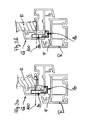
- Figure 1a illustrates the axis 100, in which a handle is inserted into the long leg 1a of the L-shaped housing 1, which can be seen in cross section from Figure 1b.
- the short leg 1b of the same flat housing can be seen in FIG. 1b, in it a second axis 102 is provided, in which a motion converter works as a flat pinion 30.
- the movement converter as a rotation converter 30 can be seen in FIG. 1a in its movement space shown there by recessing the edge of the short leg, the two compensating pieces 40b, 40a can be seen more clearly from the exploded view in FIG .
- a flat moves Insert 21 in a direction A, so that a first implementation of a rotary movement in a linear motion.
- This linear movement A is from the flat one Drive rod 10a added to a first movement component B in one Direction of locking or unlocking.
- With the movement of the flat tooth piece 21 is on the underside of the second toothing Rotation converter 30 actuated, which is set into a rotary movement C when the first drive rail 10a moves linearly.
- the gearbox is housed in the L-shaped box, which is a flat short Has leg 1b and a flat long leg 1a, the overall shape Is L-shaped, so that there is no overall box-shaped training, but an offset of the long leg with respect to the axis 102 of the short Thigh.
- Level E10 is located directly above move the drive rails 10a, 10b in opposite directions.
- FIG. 1b shows the two tooth pieces 21, 22, with a lower second one Tooth piece 22 runs only in the short leg, while the other higher Tooth piece 21 with the tooth areas arranged on both ends of its surface runs both in the short leg 1b and in the long leg 1a.
- the respective angular housing plates 1a ', 1a “and 1b', 1b” are from Figure 2 in their essential shape can be seen, two flat housing plates 1a ', 1a “and 1b ', 1b "give one of the two legs 1a, 2a of the L gearbox, the respective longitudinal end face by further angling the respective plate is covered.
- the width of the drive rails outside the short leg about the width of the finished short leg of the Gearbox corresponds.
- One is in the flat leg of the gear housing further gradation is provided, which ensures that two gear rods in the Level E10 come to lie side by side and in opposite directions in this level are movable.
- the second gradation viewed from the outside in and on the mutually facing inner edges of the two flat bars 10a, 10b at least half the width of the flat rails 10a, 10b, so that for one like that other of the two flat rails will get the same shape, despite being different directed direction of movement.
- the two flat Driving rods 10a, 10b are also two axially successive gradations intended; the one gradation corresponds to the previously described first Gradation when entering the short leg of the flat case, the second Recess corresponds to the linear tooth piece inserted vertically, to form-fit the force from a rotary movement into a linear movement or vice versa.
- the linear Tooth pieces also formed by bending directly and in one piece from the drive rods be, so that no separate insert parts are required.
- the two short shims 40a, 40b can be lengthways in the manner be elongated so that it is continuous outside the flat leg Forms cover rail for the adjacent opposing drive rods 10a, 10b.
- Figure 3a and Figure 3b show installation options of the flat counter-rotating gear with the long leg 1a to clearly behind the front end of the wing surface insert E, which will usually be a glass pane.
- the sash profile S in both representations is made of plastic and the clearance F or the area between the fixed frame R (fixed frame) and the movable sash S takes up the short leg 1b.
- the conversion of the rotary movement in the axis 100 into an opposite longitudinal movement of the drive rails 10a, 10b which is not shown in more detail in these figures, does not take place in the sash frame and also not in the groove of the sash frame, but outside the profile, in the air gap area F.
Abstract
Description
Das technische Gebiet der Erfindung sind gegenläufige Getriebe zum Einsatz in einer stirnseitigen Ausnehmung eines Flügels. Der Kasten, in dem das Getriebe angeordnet ist, ist L-förmig und seine beiden Schenkel, von denen der eine länger ist, sind flacher Gestalt, woraus sich die Begriffsdefinition des "Getriebe-Flachkasten mit L-förmiger Gestalt" ergibt. Angetrieben wird diese Getriebe durch einen Betätigungsgriff, der durch eine entsprechende Ausnehmung mit einem Mehrkantstab durch den langen Schenkel des flachen L-Getriebekastens greift.The technical field of the invention are counter-rotating transmissions for use in a front recess of a wing. The box in which the gearbox is arranged is L-shaped and its two legs, one of which is longer, are flatter Shape, from which the definition of the term "gear box with L-shaped Gestalt "results. This gear is driven by an operating handle, which by a corresponding recess with a polygonal rod through the long leg of the flat L gearbox engages.
Der kurze Schenkel solcher Getriebe wird parallel zur Stirnseite eines Flügels zum Falzbereich zeigend angeordnet, der lange Schenkel reicht in die Ausnehmung des Flügels, die bei den Offset-Getrieben bis hinter das stirnseitige Ende der im Rahmenteil des Flügels eingesetzten Glasscheibe reicht. Ohne einen solchen Getriebe-Flachkasten mit L-förmiger Gestalt zeigt die EP-A 501 803 (Regent Lock) zur Steuerung von "shooting bolts" 21,22 in dortiger Figur 4 ein gegenläufiges Getriebe, das aber mit seinem langgestreckt-quaderförmigen Getriebekasten sehr voluminös ist. Zwei flache Getriebekästen mit jeweils L-förmiger Gestalt, von denen der eine den (nicht gegenläufigen) Antrieb der durchgehenden Treibstange erfüllt und der andere die Umsetzung in eine gegenläufige Bewegung eines verlängerten Treibstangen-Abschnitts erfüllt, ist aus GB 2,277,958 (Plus Plan) bekannt.The short leg of such gears is arranged parallel to the end face of a wing pointing towards the rebate area, the long leg extends into the recess of the wing, which in offset gears extends behind the front end of the glass pane used in the frame part of the wing. Without such a gearbox flat box with an L-shaped design, EP-A 501 803 (Regent Lock) for controlling "shooting bolts" 21, 22 in FIG. 4 shows a counter-rotating gearbox, but with its elongated cuboid gearbox is very voluminous is. GB 2,277,958 (Plus Plan) discloses two flat gear boxes, each with an L-shaped shape, one of which fulfills the (non-opposite) drive of the continuous drive rod and the other of which converts an extended movement of an extended drive rod section.
Es ist Aufgabe der Erfindung, ein gegenläufige Getriebe so auszugestalten, daß es einen geringeren Raum beansprucht und mit einer Bewegungsumsetzung direkt in dem Getriebekasten arbeitsfähig ist.It is an object of the invention to design a counter-rotating gear so that it takes up less space and is capable of working directly in the gearbox with a movement implementation.
Das wird in einem L-Getriebekasten erreicht. Seine beiden Schenkel, von denen der
eine länger ist, sind flacher Gestalt. Die Treibstange ist zweigeteilt im kurzen Schenkel
angeordnet und ein Rotations-Umsetzer wird im selben kurzen Schenkel des
L-Getriebekastens angeordnet. Der Antrieb des Rotations-Umsetzer erfolgt von dem
langen Schenkel des L-Getriebekastens aus. Der Rotations-Umsetzer überträgt die
Längs-Bewegungsrichtung der einen Treibstange in eine gegenläufige Längs-Bewegung
der anderen Treibstange (Anspruch 1, 11 oder 12).This is achieved in an L gear box. His two thighs, one of which
one that is longer are flat in shape. The drive rod is divided into two in the short leg
arranged and a rotary converter is in the same short leg of the
L gearbox arranged. The rotation converter is driven by the
long leg of the L gearbox. The rotary converter transmits the
Longitudinal direction of movement of a drive rod in an opposite longitudinal movement
the other drive rod (
In schmalen Profilen ist oft kein Raum für die Einbringung eines Getriebekastens im Profil, so daß gemäß der Erfindung nur die notwendige Übertragung der Drehbewegung aus dem längeren Schenkel vorgenommen wird und alle weiteren Kupplungen oder Umsetzungen in die Falzluft verlagert werden können. In narrow profiles there is often no space for installing a gearbox in the Profile, so that according to the invention only the necessary transfer of Rotational movement is made from the longer leg and all others Couplings or implementations can be shifted into the air gap.
Auf der von der Achse des Betätigungsgriffs (am langen Schenkel) her abgewandten Seite überträgt der Rotations-Umsetzer die gegenläufigen Längs-Bewegungen der zweigeteilten TreibstangeOn the side facing away from the axis of the operating handle (on the long leg) The rotary converter transmits the opposite longitudinal movements of the two-part drive rod
Der rotatorisch arbeitende Umsetzer ist dabei im kurzen Schenkel des L-Getriebekastens drehgelagert, bevorzugt senkrecht unterhalb der Achse, in der der Betätigungsgriff zum gegenläufigen Betätigen des Getriebes eingesetzt wird, so daß beide Achsen in einer zur Treibstangenebene senkrechten Ebene zu liegen kommen.The rotary converter is in the short leg of the L gearbox rotatably mounted, preferably perpendicularly below the axis in which the Operating handle is used to operate the transmission in opposite directions, so that both axes come to lie in a plane perpendicular to the connecting rod plane.
Die Übertragung der Drehbewegung des Betätigungsgriffes erfolgt über einen Ritzelsektor, der über einen linearen Zahnstangen-Abschnitt die erste der beiden Treibschienen in Längsrichtung antreibt (Anspruch 3).The rotary movement of the operating handle is transmitted via a Pinion sector, the first of the two over a linear rack section Driving rails in the longitudinal direction (claim 3).
Dabei kann die Antriebsbewegung für den Rotations-Umsetzer entweder direkt von dem linearen Zahnstück auf den Rotations-Umsetzer übertragen werden oder aber über die Treibstange indirekt aufgebracht werden. Auf der anderen Seite des Rotations-Bewegungsumsetzers wird ein vergleichbares lineares Zahnstück angeordnet, das die Rotationsbewegung des Rotations-Umsetzers wieder in eine lineare Bewegung in gegenläufiger Richtung umsetzt.The drive movement for the rotary converter can either be directly from the linear tooth piece can be transferred to the rotary converter or else indirectly applied via the drive rod. On the other side of the Rotational motion converter becomes a comparable linear tooth piece arranged that the rotational movement of the rotary converter back into a translates linear movement in the opposite direction.
Die linearen Zahnstücke können Einsetzteile sein (Anspruch 4), die auf der Seite des Rotations-Umsetzers einen linearen Zahnabschnitt tragen. Das Einsatzstück auf der Seite des Ritzelabschnitts zum Betätigungsgriff hat dabei einen zweiten Zahnabschnitt auf der anderen Seite des flachen Einsatzstücks; das Einsatzstück auf der der Seite der gegenläufig arbeitenden Treibschiene hat nur eine zur Ausnehmung in der Treibschiene passende Gestalt, um formschlüssig oder kraftschlüssig die Bewegung in Längsrichtung auf die zweite Treibschiene auszuüben.The linear tooth pieces can be insert parts (claim 4) on the side of the Rotation converter wear a linear tooth section. The insert on the Side of the pinion section to the actuating handle has a second tooth section on the other side of the flat insert; the insert on the side the opposing working rail has only one for recess in the The shape of the drive rail to ensure that the movement is positive or non-positive Exercise longitudinally on the second drive rail.
Sollen Bauelemente eingespart werden, können auch zwei gleiche flache (nicht hohe) Zahnstücke verwendet werden. In einer anderen Ausgestaltung (Anspruch 5) können die Zahnstücke auch jeweils abgebogene Abschnitte der Treibstangen selbst sein, so daß die Einsatzstücke nicht gesondert hergestellt werden müssen, sondern integrierter Bestandteil einer jeweiligen Treibschiene sind.If components are to be saved, two identical flat (not high) Tooth pieces are used. In another embodiment (claim 5) can the tooth pieces are each also bent sections of the drive rods themselves, so that the inserts do not have to be manufactured separately, but more integrated Are part of a respective drive rail.
Um das im Durchmesser relativ kleine Ritzel von beiden Zahnstücken aus zuverlässig zu koppeln, kann die Verzahnung zu diesem Rotations-Umsetzer enger sein, als die Verzahnung zwischen dem Betätigungsgriff und dem einen der beiden linearen Zahnstücke. Reliably around the pinion with a relatively small diameter from both tooth pieces to couple, the gearing to this rotary converter can be narrower than that Tooth between the operating handle and one of the two linear Tooth pieces.
Der Aufbau im kurzen Schenkel des gegenläufigen Getriebes ist zweischichtig in zwei übereinanderliegenden Ebenen, die Ebene der Treibschienen, in denen diese gegenläufig arbeiten, und die Ebene des Bewegungs-Umsetzers direkt unterhalb der Treibschiene (Anspruch 9). Auf beiden Seiten des Ritzels in Richtung der beiden Treibschienen kann dabei ein Ausgleichsstück vorgesehen sein, das auch so verlängert sein kann, daß sich eine durchgehend erscheinende Deckschiene direkt unterhalb der gegenläufig arbeitenden Treibschienen ergibt (Anspruch 10).The structure in the short leg of the counter-rotating gearbox has two layers in two superimposed levels, the level of the driving rails in which these work in opposite directions, and the level of the motion converter directly below the Driving rail (claim 9). On both sides of the pinion towards the two Driving rails can be provided a compensating piece, which is also so can be extended that a continuous cover rail directly below the opposing driving rails results (claim 10).
Die Deckschiene ist im Getriebekasten gehalten, unterbrochen von einem flachen Getrieberaum, in dem das Ritzel die Umsetzung der Bewegungsrichtung der einen Treibstange in die Nähe der anderen Treibstange vornimmt. Dieser Raum sollte die Höhe des Ritzels etwa haben, um eine reibungsfreie Drehbewegung zu erlauben, so daß die Stärke des Ritzels an die Stärke der Deckschiene angepaßt sein sollte (Anspruch 2).The cover rail is held in the gear box, interrupted by a flat one Gearbox, in which the pinion implements the direction of movement of one The drive rod near the other drive rod. This room should be the one Have the height of the pinion to allow a smooth rotation, so that the thickness of the pinion should be adapted to the thickness of the cover rail (Claim 2).
Die Ausbildung der Treibschienen im Getriebekasten ist punktsymmetrisch zur Achse des Rotations-Umsetzers (Anspruch 7). So können zwei identische Treibstangen als gegenläufige Treibstangen verwendet werden.The design of the drive rails in the gearbox is point-symmetrical to the axis the rotary converter (claim 7). So two identical drive rods can be used as opposing drive rods are used.
Die Ausbildung des jeweiligen Endes einer Treibstange kann doppelt stufig an der jeweiligen Kante bzw. Rand sein (Anspruch 8), wobei die eine der Stufen in Richtung der Längsbewegung B, E eine Verjüngung zum Einlauf in den flachen Schenkel des Getriebekastens ermöglichst und die zweite Stufe auf der nach außen weisenden Seite das flache lineare Zahnstück aufnimmt, um formschlüssig Kraft zur Bewegung der Treibstange aufzubringen. Die andere Kante der Treibschiene ist aber deutlicher abgestuft, so daß etwa die Hälfte der ursprünglichen Breite der jeweiligen Treibschiene ausgenommen ist, um die zwei Treibschienen in dem mittleren Bereich des Getriebes, oberhalb des flachen Getrieberaums des Bewegungs-Umsetzers parallel zu führen, so daß der Getrieberaum hälftig von der einen und hälftig von der anderen Treibschiene abgedeckt wird. Die beiden Treibschienen greifen so komplementär ineinander und werden durch Wirkung des direkt benachbart angeordneten Bewegungs-Umsetzers gegenläufig ausgefahren oder eingezogen. Die andere Kante hat auch eine der ersten Stufe der ersten Kante quer gegenüberliegende Stufe gleicher Abmessung. Der Getriebekasten steht so seitlich nicht ab, gegenüber der Treibstangenbreite.The formation of the respective end of a connecting rod can be carried out in two stages respective edge or edge (claim 8), wherein one of the steps in the direction the longitudinal movement B, E a taper for entry into the flat leg of the Gear box and the second stage on the outward-facing side the flat linear tooth piece absorbs positive force to move the Apply driving rod. The other edge of the drive rail is clearer graded so that about half the original width of the respective drive rail except for the two drive rails in the middle area of the gearbox, to run parallel above the flat gear space of the motion converter, see above that the gearbox half from one and half from the other drive rail is covered. The two drive rails mesh and complement each other through the action of the directly adjacent motion converter extended or retracted in opposite directions. The other edge also has one of the first Step of the first edge transversely opposite step of the same dimension. Of the The gearbox does not stick out to the side compared to the drive rod width.
Die Umsetzung der Drehbewegung in der Achse, in der der Betätigungsgriff eingesetzt, in die gegenläufige Längsbewegung auf die Treibstange erfolgt so, daß nach Anbringung des Getriebes am Flügel im Falz oder in der Falzluft die Umsetzung vorgenommen wird, umschlossen von dem kurzen Schenkel bzw. seinem Gehäuse. Die Falzluft ist bei schmalen oder flachen Flügelprofilen der einzige Raum, der für eine solche Umsetzung zur Verfügung steht und erfindungsgemäß wird dieser Raum vorteilhaft dafür verwendet, die Gegenläufigkeit zu erzeugen.Implementing the rotational movement in the axis in which the operating handle is used, in the opposite longitudinal movement on the drive rod takes place so that after Attaching the gearbox to the sash in the rebate or in the rebate clearance is the implementation is made, enclosed by the short leg or its housing. With narrow or flat sash profiles, the rebate clearance is the only space that is available for one such implementation is available and according to the invention, this space used advantageously to create the opposite.
Die Montage des Getriebes gemäß der Erfindung erfolgt bevorzugt bei Rahmenprofilen oder Flügelprofilen aus Kunststoff oder Metall und kann sowohl bei Schwenkflügeln als auch bei Kippflügeln mit horizontaler oder vertikaler Achse Einsatz finden.The assembly of the transmission according to the invention is preferably carried out with frame profiles or wing profiles made of plastic or metal and can be used both with swivel wings can also be used with bottom-hung sashes with a horizontal or vertical axis.
Das gegenläufige Getriebe gemäß der Erfindung eignet sich sowohl für die Verwendung von stirnseitig aufliegenden (freiliegenden) Treibschienen, als auch für solche, die noch von einer Deckschiene bedeckt sind. Aufgrund der geringen Breite oder der geringen Stärke des längeren Schenkels kann das erfindungsgemäße Getriebe in seiner Einbautiefe nahezu beliebig variiert werden, so daß es sich platzsparend zwischen die Oberfläche des Rahmens und den stirnseitigen Endbereich des Flügel-Flächeneinsatzes zu legen vermag. Außerdem kann der lange Schenkel des Getriebes sich weit in das Rahmenprofil erstrecken, bis fast an dessen inneren Rand. Rahmenprofil-Hohlräume werden mit hohem Füllfaktor ausfüllbar, mit anderen Worten, das Rahmenprofil darf flacher und weniger voluminös sein. The counter-rotating transmission according to the invention is suitable for both Use of exposed (exposed) drive rails, as well as for those that are still covered by a cover rail. Because of the small width or the low thickness of the longer leg can be the inventive Gear in its installation depth can be varied almost arbitrarily, so that it space-saving between the surface of the frame and the front end area of the wing area insert is able to place. In addition, the long leg of the transmission extend far into the frame profile, almost to the inside Edge. Frame profile cavities can be filled with a high fill factor, with others Words, the frame profile may be flatter and less voluminous.
Die Erfindung(en) werden nachfolgend anhand mehrerer Ausführungsbeispiele erläutert und ergänzt.
-
Figur 1a - ist eine Teilansicht eines auseinandergenommenen gegenläufigen
Getriebes mit nur noch einer
Treibstange 10a und derAchse 100, in der ein nicht dargestellter Betätigungsgriff zum formschlüssigen Eingriff in einen Sektor-Ritzelabschnitt 20 mitAufnahme 19 eingesteckt wird. -
Figur 1b - ist ein Schnitt eines
Gehäuses 1 mit L-förmige Gestalt, bei dem die beiden Gehäuseschenkel, derlange Schenkel 1a und derkurze Schenkel 1b sehr flach ausgestaltet sind. Dargestellt ist die schonerwähnte Achse 100 zum Einsetzen des Betätigungsgriffes und die dazusenkrechte Achse 102 eines Rotations-Umsetzers 30 am Boden des flachen Schenkels, der die zum Falz zeigende Gehäuseplatte darstellt. - Figur 2
- ist eine auseinandergenommen dargestellte Zusammenstellung aller
Funktionselemente eines gegenläufigen Getriebes mit zwei gegenläufig
arbeitenden Treibstangen 10a,10b, deren jeweilige Bewegungsrichtung B und E durch Pfeile symbolisiert ist. - Figur 3a, Figur 3b
- sind ausschnittsweise Darstellungen eines Querschnitts der Einbauweise
des L-förmigen Offset-
Getriebes 1 in den Flügel S aus Kunststoff mit einer eingefügten Glasscheibe E am Glasanlageabschnitt G, welcher Flügel S im übrigen nicht ganz dargestellt ist.
- Figure 1a
- is a partial view of a disassembled counter-rotating gear with only one
drive rod 10a and theaxis 100, in which an operating handle, not shown, is inserted for positive engagement in asector pinion section 20 withreceptacle 19. - Figure 1b
- is a section of a
housing 1 with an L-shaped shape, in which the two housing legs, thelong leg 1a and theshort leg 1b are very flat. Shown is the already mentionedaxis 100 for inserting the actuating handle and theaxis 102, which is perpendicular thereto, of arotation converter 30 on the bottom of the flat leg, which represents the housing plate pointing towards the fold. - Figure 2
- is a disassembled compilation of all functional elements of a counter-rotating gear with two
counter-rotating drive rods 10a, 10b, the respective direction of movement B and E is symbolized by arrows. - Figure 3a, Figure 3b
- are partial representations of a cross section of the installation of the L-
shaped offset gear 1 in the wing S made of plastic with an inserted glass pane E on the glass contact section G, which wing S is not shown in the rest.
Figur 1a veranschaulicht die Achse 100, in der ein Handgriff in den langen
Schenkel 1a des L-förmigen Gehäuses 1, das aus Figur 1b im Querschnitt ersichtlich
ist, eingesteckt wird. der kurze Schenkel 1b des selben Flachgehäuses ist aus Figur 1
b ersichtlich, in ihm ist eine zweite Achse 102 vorgesehen, in der ein Bewegungs-Umsetzer
als flaches Ritzel 30 arbeitet. Der Bewegungs-Umsetzer als Rotations-Umsetzer
30 ist in Figur 1a in seinem dort dargestellten Bewegungsraum durch
Ausnehmung der Randseite des kurzen Schenkels ersichtlich, die beiden
Ausgleichsstücke 40b, 40a sind aus der Explosionsdarstellung der Figur 2 deutlicher
erkennbar. Figure 1a illustrates the
Das Getriebe wird im folgenden ohne spezifischen Bezug auf eine der erwähnten
Figuren beschrieben. Am deutlichsten ergibt sich die Funktion in der
Explosionsdarstellung der Figur 2 und den eingezeichneten
Bewegungsrichtungen A, B, C, D und E der zugehörigen jeweiligen
Bauelemente 21, 10a, 30, 22, 10b. The transmission is described below without specific reference to any of the above
Figures described. The function emerges most clearly in the
Exploded view of Figure 2 and the drawn
Directions of movement A, B, C, D and E of the associated
Ausgehend von einer Rotationsbewegung, die über den Betätigungshebel auf den
Sektor 20 mit grober Zahnung aufgebracht wird, bewegt sich ein flaches
Einsatzstück 21 in eine Richtung A, so daß eine erste Umsetzung einer Drehbewegung
in eine lineare Bewegung erfolgt. Diese lineare Bewegung A wird von der flachen
Treibstange 10a aufgenommen, um eine erste Bewegungskomponente B in die eine
Richtung der Verriegelung oder Entriegelung zu erhalten. Mit der Bewegung des
flachen Zahnstücks 21 wird an dessen Unterseite über eine zweite Verzahnung der
Rotations-Umsetzer 30 betätigt, der in eine Drehbewegung C versetzt wird, wenn die
erste Treibschiene 10a sich linear bewegt. Die Rotations-Umsetzung erfolgt auf der
anderen Seite des Getriebes wiederum in eine Längsbewegung durch einen anderen
flachen Zahnabschnitt 22, der im dargestellten Beispiel nur einen unteren Zahnbereich
hat und oben stumpf abschließt, um formschlüssig in eine andere Treibschiene 10b
einzugreifen, die sich bei Bewegung des Zahnstücks 22 in Richtung D in die selbe
Richtung E längsbewegt. Damit ist der grundlegende Bewegungs-Übertragungsverlauf
von der Drehbewegung des Betätigungsgriffes über die erwähnten fünf Elemente des
gegenläufigen Getriebes sowohl in eine Richtung auf die eine Treibstange 10a als auch
in die andere Richtung der anderen Treibstange 10b erläutert.Starting from a rotational movement that the operating lever on the
Das Getriebe ist in dem L-förmigen Kasten untergebracht, das einen flachen kurzen
Schenkel 1b und einen flachen langen Schenkel 1a hat, wobei die Gesamtgestalt
L-förmig ist, so daß sich keine insgesamt kastenförmige Ausbildung ergibt, sondern
eine Versetzung des langen Schenkels gegenüber der Achse 102 des kurzen
Schenkels. Senkrecht zur Achse 102, die die Achse des Bewegungs-Umsetzers 30 als
Ritzel ist, liegen zwei Ebenen E10, E40, wobei in der einen Ebene E40 sowohl das
Ritzel 30 als auch die beiden (flachen) Ausgleichsstücke 40a, 40b im kurzen
Schenkel 1b des Flachkastens liegen. Direkt oberhalb liegt die Ebene E10, in der sich
die Treibschienen 10a, 10b gegenläufig bewegen. Ersichtlich an der Schittdarstellung
der Figur 1b sind die beiden Zahnstücke 21, 22, wobei ein niedrigeres zweites
Zahnstück 22 nur im kurzen Schenkel verläuft, während das andere höhere
Zahnstück 21 mit den auf beiden Enden seiner Fläche angeordneten Zahnbereichen
sowohl im kurzen Schenkel 1b als auch im langen Schenkel 1a verläuft.The gearbox is housed in the L-shaped box, which is a flat short
Has
Die jeweils winkelförmigen Gehäuseplatten 1a', 1a" und 1b', 1b" sind aus Figur 2 in
ihrer wesentlichen Gestalt ersichtlich, jeweils zwei flache Gehäuseplatten 1a', 1a" und
1b', 1b" geben einen der beiden Schenkel 1a, 2a des L-Getriebekastens, wobei die
jeweilige Längs-Stirnseite durch eine weitere Abwinkelung der jeweiligen Platte
verdeckt wird. The respective
Einer Erläuterung sollte noch die Gestalt der Abstufung der Treibschienen 10, 10b bedürfen.The shape of the gradation of the drive rails 10, 10b should also be explained need.
Sie sind - wie aus Figur 1a ersichtlich - zunächst schwach abgestuft, um in den kurzen
Schenkel des Getriebe-Flach kastens 1 einzulaufen, wobei die Breite der Treibschienen
außerhalb des kurzen Schenkels etwa der Breite des fertigen kurzen Schenkels des
Getriebegehäuses entspricht. Im flachen Schenkel des Getriebegehäuses wird eine
weitere Abstufung vorgesehen, die dafür sorgt, daß zwei Getriebestangen in der
Ebene E10 nebeneinander zu liegen kommen und gegenläufig in dieser Ebene
bewegbar sind. Die zweite Abstufung, jeweils betrachtet von außen nach innen und an
den zueinander weisenden Innenkanten der beiden Flachstangen 10a, 10b ist
zumindest die Hälfte der Breite der Flachschienen 10a, 10b, so daß für die eine wie die
andere der beiden Flachschienen dieselbe Gestalt erhalten wird, trotz unterschiedlich
gerichteter Bewegungsrichtung.As can be seen from FIG
Leg of the gearbox
An der jeweiligen nach außen zeigenden Kante der beiden flachen
Treibstangen 10a,10b sind auch zwei axial nacheinanderliegende Abstufungen
vorgesehen; die eine Abstufung korrespondiert mit der zuvor beschriebenen ersten
Abstufung beim Einlaufen in den kurzen Schenkel des Flachgehäuses, die zweite
Ausnehmung korrespondiert mit dem vertikal dazu eingesetzten linearen Zahnstück,
um formschlüssig die Kraft von einer Drehbewegung in eine Linearbewegung oder
umgekehrt zu übertragen.On the respective outward-facing edge of the two
In einer anderen, nicht bildlich dargestellten Ausführungsform können die linearen Zahnstücke auch durch Ausbiegen direkt und einstückig aus den Treibstangen gebildet werden, so daß keine gesonderten Einsetzteile erforderlich sind.In another embodiment, not illustrated, the linear Tooth pieces also formed by bending directly and in one piece from the drive rods be, so that no separate insert parts are required.
Die beiden kurzen Ausgleichsstücke 40a, 40b können in Längsrichtung in der Weise
verlängert sein, daß sie eine außerhalb des flachen Schenkels durchgehende
Deckschiene für die benachbart geführten gegenläufigen Treibstangen 10a, 10b bildet. The two
Figur 3a und Figur 3b zeigen Einbaumöglichkeiten des flachen gegenläufigen
Getriebes mit dem langen Schenkel 1a bis deutlich hinter das stirnseitige Ende des
Flügel-Flächeneinsatzes E, der meist eine Glasscheibe sein wird. Das
Flügelrahmenprofil S in beiden Darstellungen ist aus Kunststoff und die Falzluft F oder
der Bereich zwischen dem feststehenden Blendrahmen R (Festrahmen) und dem
beweglichen Flügelrahmen S nimmt den kurzen Schenkel 1b auf. Die in diesen Figuren
nicht näher dargestellte Umsetzung der Drehbewegung in der Achse 100 in eine
gegenläufige Längsbewegung von Treibschienen 10a,10b erfolgt nicht im
Flügelrahmen und auch nicht in der Nut des Flügelrahmens, sondern außerhalb des
Profils, im Falzluft-Bereich F. Figure 3a and Figure 3b show installation options of the flat counter-rotating gear with the
Claims (12)
Applications Claiming Priority (2)
| Application Number | Priority Date | Filing Date | Title |
|---|---|---|---|
| DE1997154880 DE19754880C5 (en) | 1997-12-10 | 1997-12-10 | Reverse gear with offset gear box |
| DE19754880 | 1997-12-10 |
Publications (2)
| Publication Number | Publication Date |
|---|---|
| EP0922827A1 true EP0922827A1 (en) | 1999-06-16 |
| EP0922827B1 EP0922827B1 (en) | 2006-06-14 |
Family
ID=7851446
Family Applications (1)
| Application Number | Title | Priority Date | Filing Date |
|---|---|---|---|
| EP19980123608 Expired - Lifetime EP0922827B1 (en) | 1997-12-10 | 1998-12-10 | Espagnolette with rods sliding in opposite directions and offset housing |
Country Status (2)
| Country | Link |
|---|---|
| EP (1) | EP0922827B1 (en) |
| DE (2) | DE19754880C5 (en) |
Cited By (3)
| Publication number | Priority date | Publication date | Assignee | Title |
|---|---|---|---|---|
| WO2005021908A1 (en) * | 2003-08-22 | 2005-03-10 | Siegenia-Aubi Kg | Driving bar closure |
| GB2378982B (en) * | 2001-08-23 | 2006-02-22 | Trojan Hardware & Designs Ltd | Drive mechanism for shoot bolts |
| US11454054B2 (en) * | 2016-09-08 | 2022-09-27 | Nifco Inc. | Lock device |
Citations (3)
| Publication number | Priority date | Publication date | Assignee | Title |
|---|---|---|---|---|
| FR2335678A1 (en) * | 1975-12-19 | 1977-07-15 | Siegenia Frank Kg | MECHANISM INVERTING THE DIRECTION OF PUSHING FOR SPANISH WITH RETAINING RODS |
| GB2252351A (en) * | 1991-01-15 | 1992-08-05 | Crompton Ltd | Operating mechanism for espagnolette fastening systems |
| GB2289709A (en) * | 1994-04-22 | 1995-11-29 | Derek King | Espagnolette operating mechanism |
Family Cites Families (2)
| Publication number | Priority date | Publication date | Assignee | Title |
|---|---|---|---|---|
| DE69207792D1 (en) * | 1991-02-28 | 1996-03-07 | Regent Lock Co Ltd | Espagnolette lock mechanism |
| GB9309703D0 (en) * | 1993-05-12 | 1993-06-23 | Plus Plan Uk Ltd | Locking system for doors and windows |
-
1997
- 1997-12-10 DE DE1997154880 patent/DE19754880C5/en not_active Expired - Fee Related
-
1998
- 1998-12-10 DE DE59813596T patent/DE59813596D1/en not_active Expired - Lifetime
- 1998-12-10 EP EP19980123608 patent/EP0922827B1/en not_active Expired - Lifetime
Patent Citations (3)
| Publication number | Priority date | Publication date | Assignee | Title |
|---|---|---|---|---|
| FR2335678A1 (en) * | 1975-12-19 | 1977-07-15 | Siegenia Frank Kg | MECHANISM INVERTING THE DIRECTION OF PUSHING FOR SPANISH WITH RETAINING RODS |
| GB2252351A (en) * | 1991-01-15 | 1992-08-05 | Crompton Ltd | Operating mechanism for espagnolette fastening systems |
| GB2289709A (en) * | 1994-04-22 | 1995-11-29 | Derek King | Espagnolette operating mechanism |
Cited By (3)
| Publication number | Priority date | Publication date | Assignee | Title |
|---|---|---|---|---|
| GB2378982B (en) * | 2001-08-23 | 2006-02-22 | Trojan Hardware & Designs Ltd | Drive mechanism for shoot bolts |
| WO2005021908A1 (en) * | 2003-08-22 | 2005-03-10 | Siegenia-Aubi Kg | Driving bar closure |
| US11454054B2 (en) * | 2016-09-08 | 2022-09-27 | Nifco Inc. | Lock device |
Also Published As
| Publication number | Publication date |
|---|---|
| EP0922827B1 (en) | 2006-06-14 |
| DE19754880C5 (en) | 2004-10-21 |
| DE59813596D1 (en) | 2006-08-24 |
| DE19754880C2 (en) | 2002-10-24 |
| DE19754880A1 (en) | 1999-06-24 |
Similar Documents
| Publication | Publication Date | Title |
|---|---|---|
| DE2345496A1 (en) | DRIVE ROD FITTING, IN PARTICULAR PLUG-IN EDGE DRIVES, FOR THE LEAF OF WINDOWS, DOORS OR. DGL | |
| EP0641910A2 (en) | Espagnolette gearing of a window or door. | |
| EP0004325B1 (en) | Improvements in and relating to locking devices for windows, doors and the like | |
| EP0589170A1 (en) | Actuating rod fitting for windows, doors and the like | |
| EP1359273B1 (en) | Lock fitting on a window, a door or similar, with oppositely moving espagnolettes | |
| EP0883723B1 (en) | Connection rod fitting assembly set | |
| DE2557303C2 (en) | Direction of thrust reversing gear for espagnolette fittings | |
| EP0292665A2 (en) | Connecting rod for doors,windows or the like | |
| EP2143859B1 (en) | Locking device | |
| EP1216335B1 (en) | Intermediate gear for window or door fittings | |
| DE10354185B4 (en) | espagnolette | |
| EP0922827B1 (en) | Espagnolette with rods sliding in opposite directions and offset housing | |
| EP0493689A1 (en) | Espagnolette for windows, doors or the like | |
| EP1159502A1 (en) | Window or door | |
| DE2118473C3 (en) | Gear for window closures | |
| DE4040302C2 (en) | Actuating gear for window and door locks or the like | |
| DE2725982A1 (en) | LOCKING GEAR FOR WINDOWS, DOORS OR DGL. | |
| DE10322778B4 (en) | Driving rod drive | |
| DE202007006223U1 (en) | Operating unit for window frame, comprises T-shaped extension at connecting rod serving as distancer | |
| DE4324584C1 (en) | Driving-rod mechanism for door or window | |
| DE2923460C2 (en) | Right and left usable espagnolette lock | |
| EP0784142A2 (en) | Actuating mechanism for window and/or door fittings with actuating- and/or locking-rods or the like | |
| DE2461228B2 (en) | Method for producing a ready-to-install window or door lock that is adapted to a given sash height | |
| EP0785329B1 (en) | Actuating mechanisme for an espagnolette fitting | |
| DE102005000177A1 (en) | Window or door |
Legal Events
| Date | Code | Title | Description |
|---|---|---|---|
| PUAI | Public reference made under article 153(3) epc to a published international application that has entered the european phase |
Free format text: ORIGINAL CODE: 0009012 |
|
| AK | Designated contracting states |
Kind code of ref document: A1 Designated state(s): DE GB IE |
|
| AX | Request for extension of the european patent |
Free format text: AL;LT;LV;MK;RO;SI |
|
| AKX | Designation fees paid | ||
| RBV | Designated contracting states (corrected) |
Designated state(s): DE GB IE |
|
| REG | Reference to a national code |
Ref country code: DE Ref legal event code: 8566 |
|
| 17P | Request for examination filed |
Effective date: 19991215 |
|
| RBV | Designated contracting states (corrected) |
Designated state(s): DE GB IE |
|
| 17Q | First examination report despatched |
Effective date: 20010123 |
|
| GRAP | Despatch of communication of intention to grant a patent |
Free format text: ORIGINAL CODE: EPIDOSNIGR1 |
|
| RAP1 | Party data changed (applicant data changed or rights of an application transferred) |
Owner name: HAUTAU GMBH |
|
| GRAS | Grant fee paid |
Free format text: ORIGINAL CODE: EPIDOSNIGR3 |
|
| GRAA | (expected) grant |
Free format text: ORIGINAL CODE: 0009210 |
|
| RAP1 | Party data changed (applicant data changed or rights of an application transferred) |
Owner name: HAUTAU GMBH |
|
| AK | Designated contracting states |
Kind code of ref document: B1 Designated state(s): DE GB IE |
|
| REG | Reference to a national code |
Ref country code: GB Ref legal event code: FG4D Free format text: NOT ENGLISH |
|
| REG | Reference to a national code |
Ref country code: IE Ref legal event code: FG4D Free format text: LANGUAGE OF EP DOCUMENT: GERMAN |
|
| REF | Corresponds to: |
Ref document number: 59813596 Country of ref document: DE Date of ref document: 20060824 Kind code of ref document: P |
|
| GBT | Gb: translation of ep patent filed (gb section 77(6)(a)/1977) |
Effective date: 20061023 |
|
| PLBE | No opposition filed within time limit |
Free format text: ORIGINAL CODE: 0009261 |
|
| STAA | Information on the status of an ep patent application or granted ep patent |
Free format text: STATUS: NO OPPOSITION FILED WITHIN TIME LIMIT |
|
| 26N | No opposition filed |
Effective date: 20070315 |
|
| PGFP | Annual fee paid to national office [announced via postgrant information from national office to epo] |
Ref country code: GB Payment date: 20101230 Year of fee payment: 13 |
|
| PGFP | Annual fee paid to national office [announced via postgrant information from national office to epo] |
Ref country code: IE Payment date: 20111116 Year of fee payment: 14 |
|
| PGFP | Annual fee paid to national office [announced via postgrant information from national office to epo] |
Ref country code: DE Payment date: 20120228 Year of fee payment: 14 |
|
| GBPC | Gb: european patent ceased through non-payment of renewal fee |
Effective date: 20121210 |
|
| REG | Reference to a national code |
Ref country code: IE Ref legal event code: MM4A |
|
| PG25 | Lapsed in a contracting state [announced via postgrant information from national office to epo] |
Ref country code: DE Free format text: LAPSE BECAUSE OF NON-PAYMENT OF DUE FEES Effective date: 20130702 Ref country code: IE Free format text: LAPSE BECAUSE OF NON-PAYMENT OF DUE FEES Effective date: 20121210 |
|
| REG | Reference to a national code |
Ref country code: DE Ref legal event code: R119 Ref document number: 59813596 Country of ref document: DE Effective date: 20130702 |
|
| PG25 | Lapsed in a contracting state [announced via postgrant information from national office to epo] |
Ref country code: GB Free format text: LAPSE BECAUSE OF NON-PAYMENT OF DUE FEES Effective date: 20121210 |