EP0921445A2 - Entwicklungsgerät unter Verwendung einem Einkomponentenentwickler - Google Patents
Entwicklungsgerät unter Verwendung einem Einkomponentenentwickler Download PDFInfo
- Publication number
- EP0921445A2 EP0921445A2 EP98123182A EP98123182A EP0921445A2 EP 0921445 A2 EP0921445 A2 EP 0921445A2 EP 98123182 A EP98123182 A EP 98123182A EP 98123182 A EP98123182 A EP 98123182A EP 0921445 A2 EP0921445 A2 EP 0921445A2
- Authority
- EP
- European Patent Office
- Prior art keywords
- blade
- developing roller
- toner
- developing
- slant face
- Prior art date
- Legal status (The legal status is an assumption and is not a legal conclusion. Google has not performed a legal analysis and makes no representation as to the accuracy of the status listed.)
- Granted
Links
Images


Classifications
-
- G—PHYSICS
- G03—PHOTOGRAPHY; CINEMATOGRAPHY; ANALOGOUS TECHNIQUES USING WAVES OTHER THAN OPTICAL WAVES; ELECTROGRAPHY; HOLOGRAPHY
- G03G—ELECTROGRAPHY; ELECTROPHOTOGRAPHY; MAGNETOGRAPHY
- G03G15/00—Apparatus for electrographic processes using a charge pattern
- G03G15/06—Apparatus for electrographic processes using a charge pattern for developing
- G03G15/08—Apparatus for electrographic processes using a charge pattern for developing using a solid developer, e.g. powder developer
- G03G15/0806—Apparatus for electrographic processes using a charge pattern for developing using a solid developer, e.g. powder developer on a donor element, e.g. belt, roller
- G03G15/0812—Apparatus for electrographic processes using a charge pattern for developing using a solid developer, e.g. powder developer on a donor element, e.g. belt, roller characterised by the developer regulating means, e.g. structure of doctor blade
Definitions
- the present invention relates to a developing apparatus using toner which is a colorant for developing an electrostatic latent image formed on an image bearing member into a visible image, more particularly, to a developing apparatus using a one-component developer as the toner.
- Electrophotographic image forming apparatuses such as copiers, printers and the like, include a developing apparatus which is adapted to form an electrostatic latent image on a photosensitive member serving to bear the latent images, to supply a developer, such as toner which is a colorant, and to make the toner deposit selectively, thereby making the latent image visible.
- a developing apparatus which is adapted to form an electrostatic latent image on a photosensitive member serving to bear the latent images, to supply a developer, such as toner which is a colorant, and to make the toner deposit selectively, thereby making the latent image visible.
- a latent image formed on the photosensitive member is developed into a toner image which is transferred to a transfer medium such as a sheet.
- a transfer medium such as a sheet.
- the remaining toner is removed from the surface of the photosensitive member so that the photosensitive member is prepared for the subsequent image forming operation.
- a cleaner unit is provided for removing the residual toner from the photosensitive member surface after transfer operation. The toner thus removed by the cleaner unit is received by a toner chamber in the cleaner unit.
- Image forming apparatuses with a developing apparatus arranged above mentioned have been faced with a demand for downsizing.
- reduced are spaces for various processing means which are located around the photosensitive member and involved in the image forming process.
- the reduced spaces for the processing means result in a further demand for downsizing the respective processing means themselves.
- a developing roller of a magnetic brush type which utilizes a magnetic force for supplying a two-component developer composed of toner particles and a magnetic carrier to a developing region in opposing relation with the photosensitive member, and every time the development operation completes, a residual developer is recovered to a developing tank.
- control is provided for stable developing performance such that toner of consumed amount may be made up thereby to maintain a constant concentration of toner or content ratio of the toner in the developer.
- the developing apparatus of the above-mentioned type namely of the magnetic brush type tends to have a large overall size because the developer contains a greater proportion of carrier and requires a large developing tank for storage of the developer.
- a stirring member or the like is needed for maintaining a constant charge of the toner particles in the developer.
- a plurality of stirring members provided in the developing apparatus constitutes a bottleneck in the downsizing of the developing apparatus.
- a developing apparatus using a one-component developer or carrier-free toner has been proposed and put to practical use.
- Such a one-component toner developing apparatus permits the size reduction thereof because the control of toner concentration is not necessary and the absence of carriers permits the reduction of capacity of the developing tank.
- such a developing apparatus features easy maintenance. More specifically, the developing apparatus eliminates the need for a maintenance work for replacing a deteriorated developer particularly resulting from deteriorated carriers.
- the developing apparatus only needs the replenishment of toner, obviating the necessity of sensing the toner concentration. Inasmuch as control for sensing the toner concentration is not necessary, simple control may be provided. Particularly, the developing apparatus using the one-component toner only needs the replenishment of toner when required.
- the toner In the developing apparatus utilizing one-component toner, the toner must be supplied to and made to deposit on the developing roller.
- the single-component toner is magnetic toner
- the developing roller imparted with a magnetic force is capable of magnetically attracting a desired amount of toner thereby forming thereon a toner layer of a uniform thickness.
- the developing roller need to be constructed such that a plurality of magnets are disposed along a direction of rotation while an outer periphery of the arranged magnets are covered with a non-magnetic cylindrical sleeve. As a result, the apparatus tends to be increased in size.
- the developing roller is formed of an elastic material such as rubber, not relying on the magnetic force far attracting the toner. Accordingly, the developing roller may have a simple structure and a reduced diameter, thus permitting the weight reduction.
- the developing roller is not adapted to magnetically attract the toner, an important point is to bring a constant amount of toner or a uniform toner layer into contact with the photosensitive member.
- a feed roller is provided with respect to the developing roller, while a blade is provided so as to be pressed against the developing roller for regulating the toner mass per unit area, thereby maintaining the thickness of fed toner constant.
- the blade is typically configured so that a face of a sheet-like member constituting the blade is press contacted at a suitable pressure.
- the amount of toner supplied to the developing roller is regulated by suitably pressing the surface or belly of the sheet-like blade member against the developing roller whereby a uniform toner layer is formed on an overall axial area of the developing roller.
- the regulation of the toner mass per unit area may be accomplished by adjusting the setting position of the blade under the condition including both conditions of pressing the surface or belly of the blade against the roller and pressing the tip end or edge of the blade against the roller.
- This permits formation of a suitable toner layer which is constant in thickness and sufficient in quantity for performing the developing process under suitable conditions.
- this arrangement provides little allowance for the setting position of the blade, resulting in a very difficult adjustment of the setting position of the blade.
- serious variations in the toner mass per unit area depositing on the roller are caused by wear or the like of the blade so that increased frequencies of the blade replacement result.
- each blade replacement involves a very cumbersome adjustment work, thus lowering the serviceability.
- a method for stabilizing the toner mass per unit area on the developing roller has been disclosed in Japanese Unexamined Patent Publications JP-A 7-64391(1995) and JP-A 7-239611(1995). According to this method, a tip end of the blade is slightly angled for attaining a desired toner mass per unit area. This method contributes to an increased allowance for the setting position of the blade, thus negating the need for the exacting adjustment work.
- the developing apparatus disclosed in Japanese Unexamined Patent Publication JP-A 7-64391(1995) or the like provides an increased allowance for the setting position of the blade serving to maintain a constant amount of toner which is deposited on the developing roller and ensures stable toner feeding.
- an angle of aperture of a toner inlet portion defined by the blade and the developing roller is varied due to deformation of the developing roller or difference in diameter of the developing rollers. This may lead to serious variations in the toner mass per unit area deposited on the developing roller, although the blade is set to position according to predetermined conditions.
- the deformation of developing roller means that the developer roller is elastically deformed by pressing the blade against the roller.
- the difference in the diameters of the developing rollers is attributable to variations in the size of respective rollers generated in fabrications or difference in the type of the developing apparatuses.
- a metal material having a good resilience such as phosphor bronze, stainless steel and the like, is used rather than aluminum and the like which has a relatively poor resilience.
- the blade formed of such a material suffers the toner fusion to the surface thereof if it is used over an extended period of time.
- the toner fused to the blade causes variations in the thickness of the toner layer with respect to the axial direction of the developing roller, and production of partial streaks results. If the developing roller in this state is used for developing the latent image, a degraded image and the like result.
- a developing apparatus using one-component toner comprises:
- a blade 25 for regulating the toner mass per unit area is pressed against a developing roller 21 at a suitable abutment force, as shown in Fig.1.
- the abutment of the blade 25 causes deformation of the developing roller 21.
- the toner is introduced to a nip portion on which the blade 21 contacts with the developing roller 21.
- the slant face 25a or the like of the blade 25 is adjusted so that the blade 25 and the developing roller 21 in a deformed state may form an angle of aperture ⁇ of equal to or more than 12.5° at a toner inlet portion through which toner flows into a nip portion where the blade 21 contacts with the developing roller 21.
- the angle of aperture ⁇ counting the elastic deformation of the developer in is set to the aforesaid condition rather than setting a tilt angle ⁇ of the slant face 25a of the blade 25.
- This ensures that a stable toner mass per unit area and a uniform thickness of toner layer regardless of variations of elastic coefficient and diameter of the developing roller, Particularly, a sufficient allowance for the setting position of the blade is ensured by setting the angle of aperture ⁇ at a toner inlet portion to a given value with the slant face of the blade and the elastic deformation of the developing roller taken into consideration. This eliminates the need setting a specific angle of the slant face of the blade according each developing roller.
- ⁇ denotes a tilt angle of the slant face of the blade
- w denotes a nip width on which the blade contacts with the developing roller
- R denotes a radius of the developing roller.
- a developing apparatus of the above configuration is characterized in that the blade is constructed of a one-piece metal sheet-like member formed with the slant face by mechanical bending, and that a thickness of the sheet-like member is not more than 0.2mm.
- a blade suffers less distortion due to the residual stress, thus maintaining the straightness thereof.
- the blade is capable of stabilizing the toner mass per unit area on the developing roller thereby forming a uniform toner layer.
- a developing apparatus of the above configuration in characterized in that the slant face of the blade is formed by bending the sheet-like member constructing the blade along a bend line orthogonal to a rolling direction of the sheet-like member. This is also effective to eliminate the influence of distortion due to the residual stress so that the slant face formed by bending is permitted to maintain the straightness thereof adequately. Thus, a more preferable toner layer is formed.
- the slant face is manufactured by bending process while specifying a material such as quality of the sheet-like member constructing the blade, sufficient straightness may be ensured.
- the stock may be subject to the TA (tention annealing) treatment.
- a developing apparatus of the above configuration is characterized in that the mechanical bending for forming the slant face of the blade is carried out by using a mold provided with a projection at a position corresponding to a bend position on a side of the blade opposite to a side thereof abutting with the developing roller.
- the developing apparatus may be provided with the blade fabricated in this manner, with the result that a problem caused by cracks in the blade is eliminated. Thus, a uniform toner layer may be obtained.
- a developing apparatus of the above configuration is characterized in that a side face abutting with the developing roller of the blade is ground. This eliminates surface roughness due to cracks, thereby ensuring forming of a uniform toner layer.
- a developing apparatus of the above configuration is characterized in that alumite-treated aluminum foil is provided on at least a face of the blade which is on a side abutting with the developing roller. This prevents the toner from being fused to the blade and the developing roller, thereby ensuring forming of the uniform toner layer over an extended period of time.
- a developing apparatus of the above configuration is characterized in that the slant face of the blade is formed by making a step at a tip end of a sheet-like member constructing the blade, and thereafter sticking a metal foil piece so as to cover the step.
- a metal foil piece 255 is stuck to a member 254 constructing the blade 25 so as to cover a step 25c formed in the blade member 254 including a portion contacting with the developing roller. This permits the metal foil piece 255 to define the slant face 25a over the step 25c. In this case, there exists no influence of distortion due to the residual stress because mechanical bending is not performed.
- the straightness of the slant face is not impaired and therefore, the slant face is formed with a high precision.
- the step may be formed by an etching process or the like and a depth or the like of the step may be arbitrary set.
- a developing apparatus of the above configuration is characterized in that the blade is formed of two thin-sheet members stacked together with tip ends thereof being shifted from each other for forming the step, and the metal foil piece is provided so as to cover the step.
- the step 25c is formed by stacking two blade members 256, 257 together which members are shifted from each other.
- the depth of the step 25c may be readily set to an arbitrary value by selecting and controlling the thickness of one of the blade member 256.
- the lengths of the shifted end portions of the two blade members may readily be set to specified values.
- the length of the step portion may be defined with quite a high precision by cutting off the tip end of the longer blade member.
- the length of the step portion may be defined with a high precision by providing positioning portions in the two blade members.
- a metal foil piece 258 stuck on the step portion may have a thickness of 0.05 mm or less. Alumite-treated aluminum foil used for the metal foil piece 258 will effectively prevent the toner fusion.
- Fig.1 illustrates in detail a state where a developing roller and a blade constituting the developing apparatus of the invention, contact with each other, the developing apparatus being opposed to a photosensitive member which serves especially as an image bearing member of an image forming apparatus.
- Fig.2 is a diagram showing a configuration of an image forming station, particularly a developing station of the image forming apparatus equipped with the developing apparatus of the invention.
- a photosensitive member 1 composing a drum-like carrier is disposed almost in the center of the image forming apparatus and rotated at a fixed speed in the direction of an arrow when an image forming operation is performed.
- the carrier is used to carry a static latent image thereon.
- Various image forming process means are disposed around this photosensitive member 1 so as to be opposed thereto respectively.
- the above image forming process means include a charger that charges the surface of the photosensitive member 1 in uniform (not shown); an optical system that irradiates an image based on light according to the image (not shown); a developing apparatus 4 of the invention, used to visualize a static latent image formed on the surface of the photosensitive member 1 after being exposed by the optical system; a transfer member for transferring a developed image (toner image) onto a sheet-like paper fed as needed (not shown); a cleaning member for removing residual developer (toner) remained on the surface of the photosensitive member 1 after the transfer process is ended (not shown); and an eliminator for eliminating electric charge remained on the surface of the photosensitive member 1 (not shown), etc., which are all disposed in order in the rotating direction of the photosensitive member 1.
- a sheet of paper is then fed by a paper feeding means into the transfer area opposed to the photosensitive member 1, where the above-mentioned transfer member is disposed. At this time, the sheet is fed so as to be aligned to the tip of the toner image formed on the surface of the photosensitive member 1.
- the sheet after the image is transferred, is separated from the photosensitive member 1, then fed into a fixing apparatus.
- the fixing apparatus fixes a non-fixed toner image transferred onto a sheet of paper as a permanent image.
- the fixing apparatus has a heat roller heated up to a temperature for fusing toner and fixing the toner image on its surface opposed to the toner image.
- the fixing apparatus also includes a pressure roller pressed against the heat roller and used to make the sheet come in contact closely with the heat roller. The sheet passing through this fixing apparatus is ejected outside the image forming apparatus, into an ejection tray (not shown) via an ejection roller.
- the optical system (not shown) irradiates light on a copy original and outputs reflecting light from the original as a light image if a copying machine is used as an image forming apparatus. If a printer or a digital copying machine is used as an image forming apparatus, the optical system turns on/off the semiconductor laser thereby to output a light image according to image data. Especially, when a digital copying machine is used as an image forming apparatus, the optical system including the semiconductor laser receives image data obtained by reading the reflecting light from a copy original using an image read sensor (CCD element, etc.) and outputs a light image according to the image data.
- an image read sensor CCD element, etc.
- the optical system receives image data from another processing apparatus, for example, a ward processor, a personal computer, etc. and converts the data to a light image according to the image data and outputs the light image.
- a processing apparatus for example, a ward processor, a personal computer, etc.
- a semiconductor laser, but also an LED element, a liquid crystal shutter, etc. are usable for converting image data to a light image.
- the photosensitive member 1 is rotated in the direction of an arrow and the surface of the photosensitive member 1 is charged by the charger to a potential of a specific polarity in uniform.
- the optical system (not shown) outputs a light image, so that a static latent image is formed on the surface of the photosensitive member 1 according to this light image.
- This static latent image is developed in the developing apparatus in the next stage thereby to visualize the static latent image artificially.
- One-component toner is used for this developing process in the invention. The toner is sucked selectively by, for example, an electrostatic force onto a static latent image formed on the surface of the photosensitive member 1 so as to be developed.
- the transfer member disposed in the transfer area then transfers the toner image developed on the surface of the photosensitive member 1 as described above statically on a sheet fed synchronously with the rotation of the photosensitive member 1 as needed.
- the transfer member charges the back side of the sheet to a polarity opposite to the polarity of charged toner, so that the toner image is transferred onto the sheet.
- the sheet after the transfer process is ended, is separated from the photosensitive member 1 and fed to the fixing apparatus.
- this fixing apparatus the toner image on the sheet is fused, then pressed and fixed due to a pressure generated between rollers. Passing this fixing apparatus, the sheet is ejected as an image formed sheet onto a tray provided outside the image forming apparatus.
- the developing apparatus 2 comprises a developing roller 21 provided rotatably in a developing tank 20 containing one-component toner, for example, non-magnetic one-component toner; a feed roller 22 for feeding one-component toner to the developing roller 21; and two screw rollers 23, 24 on the right side of the developing tank 20 in Figure, for feeding one-component toner supplied as needed to the developing tank 20.
- one-component toner for example, non-magnetic one-component toner
- a feed roller 22 for feeding one-component toner to the developing roller 21
- two screw rollers 23, 24 on the right side of the developing tank 20 in Figure, for feeding one-component toner supplied as needed to the developing tank 20.
- the developing roller 21 is provided in the developing tank 20 so as to be partly exposed from the tank and to be rotated in the same direction as the photosensitive member 1 at a developing region for transporting the toner to the developing region where the developing roller 21 opposes the photosensitive member 1. Pressed against the developing roller 21 is the aforesaid feed roller 22.
- the developing roller 21 has a configuration in which, for example, a surface of a metal roller is coated with a porous, elastic material such as sponge. If carbon-distributed macromolecular foam polyurethane, etc. or ion conductive solid rubber is used as the elastic member such as sponge, a predetermined resistance value that prevents toner fusion can be kept and it will function effectively when developing bias voltage is supplied to the developing roller.
- the developing roller 21 is supplied with a developing bias voltage from a developing bias supply 3.
- the developing bias voltage is set to a polarity and value such as to cause the toner to deposit on the static latent image on the photosensitive member 1 but not on the other region thereof or a non-image region.
- the feed roller 22 is rotated so that a rotation direction thereof is opposite to that of the developing roller 21 at an opposing region of the feed roller 22 and the developing roller 21.
- the feed roller 22 is formed of a similar material to that of the developing roller 21, and the electric resistance thereof may be adjusted by using similar resistance adjusting materials. Further, in order to increase the elasticity, the feed roller 22 is formed of foamed materials, which contains larger amount of foaming agent than the material for the developing roller.
- a bias voltage is applied from a bias supply 4, which bias voltage is set generally so that the toner is pushed to the developing roller 21, and in a direction that the toner on the feed roller 22 is repelled, allowing the toner to be fed to the developing roller 21.
- a bias voltage is applied to the feed roller 22 smaller than the bias voltage to the developing roller 21.
- the developing roller 21 and the feed roller 22 are connected to drive motors (not shown), and each of the rollers is rotated in a direction of an arrow in Figure, thereby permitting the feed roller 22 to feed the toner to the developing roller 21 and to separate (remove) the toner remaining on the surface of the developing roller 21 after the developing process is performed.
- the toner thus fed by the feed roller 22 is deposited on the surface of the developing roller 21, and prior to being transported to the developing region opposing to the surface of the photosensitive member 1, the toner mass per unit area is regulated to a predetermined thickness by a blade 25 which is suitably pressed against the developing roller for regulating the toner mass per unit area.
- the blade 25 is pressed against the developing roller 21 at a suitable pressure.
- the blade 25 is composed of a blade member formed of a sheet-like metal material, a belly (face) in the Vicinity of the tip end thereof being pressed against the developing roller 21.
- the toner fed to the developing roller 21 is so regulated as to have a predetermined charge and thickness according to a predetermined pressure and position of the blade 25. Subsequently, the toner so regulated is transported to the developing region where the developing roller opposes the photosensitive member 1.
- a predetermined voltage is applied from a bias supply 5.
- the bias voltage to the blade 25 is set to cause the toner to be pressed to the developing roller 21.
- a bias voltage to is applied to the blade 25 smaller than the bias voltage to the feed roller 22.
- the bias voltage to be applied to the blade 25 may be set to the same potential as that applied to the developing roller 21.
- the toner transported to the developing region opposing to the photosensitive member 1 is selectively deposited on the surface of the photosensitive member 1 according to a static latent image formed thereon, and makes the static latent image apparent by virtue of colors of the toner.
- the toner not used for the image development is returned to the developing tank 20 by the rotation of the developing roller 21.
- a charge removing member 26 for toner is provided so as to be pressed against the developing roller 21.
- the charge removing member 26 is located upstream the feed roller 22 in the rotating direction of the developing roller 21, and one end thereof is fixed to the developing tank 20 while an free end thereof is pressed against the developing roller 21 by virtue of the elasticity of the charge removing member 26. As a result, the charge removing member 26 is suitably pressed against the developing roller 21.
- Charges of the toner not having used for developing are eliminated by the charge removing member when the toner is returned to the developing tank 20 by the rotating developing roller 21 and then the toner is to be recycled. Also to the charge removing member 26, a charge eliminating voltage for removing the charge from the toner is applied from a power source 6.
- the developing apparatus 2 transports the toner to the developing region where the developing apparatus 6 opposes the photosensitive member 1, thereby developing the latent image on the surface of the photosensitive member 1 into a visible image.
- the resultant toner image on the surface of the photosensitive member 1 is transferred onto a sheet fed to an image transfer region as needed, which sheet subsequently passes thorough the fixing apparatus and be ejected from the image forming apparatus.
- an OPC photosensitive member or the like comprises: a conductive base formed of metal or resin on the surface of which an under layer is applied; a carrier generating layer (CGL) laid over the under layer; and a carrier transfer layer (CTL)defining an outermost layer and principally composed of polycarbonate. It is to be understood that the invention is not limited to such a photosensitive member but applicable to any carries capable of bearing electrostatic latent images.
- the developing roller 21 includes a core bar (shaft) formed of a metal or a low-resistance resin material, and an elastic member having a relative dielectric constant of about 10 and covering the core bar.
- the elastic member covering the surface of the developing roller 21 is preferably formed of the following materials: a material based on a dispersion-type resistance adjusted resin in which conductive fine particles as an electrical resistance adjusting material, for example, either or both of carbon and TiO 2 (titanium oxide) are mixed and dispersed in a resin selected from the group consisting of EPDM, urethane, silicone, nitrile-butadien rubber, chloroprene rubber, styrene-butadiene rubber, butadiene rubber and the like; and a material based on an electric resistance adjusting resin in which an ionic conductive material, one or more of inorganic ionic conductive materials selected from the group consisting of sodium perchlorate, calcium perchlorate, sodium chlorite and the like are added to the
- silicone surfactants such as polydiallylsiloxane and polysiloxane-polyalkyne oxide block copolymer are preferably used.
- an example of a hot blow foam molding includes the steps of mixing the above-mentioned material in suitable proportions, agitating the resultant mixture by a mixer/injector, introducing the mixture into an injection-extrusion mold, heating the mixture at a temperature of between 80°C and 120°C, and injecting the molded stock.
- a preferred heating time ranges from about 5 to 100 minutes.
- an integrally molded part may be obtained by placing a conductive metal core bar (shaft) at the center of a preliminarily prepared mold, introducing the mixture into the mold similarly to the above-mentioned example, and heating and vulcanizing the mixture for a period ranging from about 10 to 160 minutes.
- carbon black included in the electric resistance adjusting materials carbon black (e.g., ISAF, HAF, GPF, SRF and the like) having a nitrogen absorption specific surface area of 20 m 2 /g or less is used, and the carbon black is mixed with polyurethane in a ratio of 0.5 to 15 parts by weight (about 70 parts in some instances) per 100 parts by weight of polyurethane.
- polyurethane examples include a soft polyurethane foam and a polyurethane elastomer.
- EPDM urethane
- urethane silicone
- nitrile-butadiene rubber nitrile-butadiene rubber
- chloroprene rubber butadiene rubber
- the EPDM which contains ethylene, propylene and a third component such as dicyclopentadiene, ethylidene norbornene, 1.4-hexadiene is preferably formed by mixing ethylene, propylene and a third component in proportions of 5 to 95 parts by weight, 5 to 95 parts by weight, and 0 to 50 parts by weight based on iodine value, respectively.
- a suitable amount of a carbon black to be mixed is 1 to 30 parts by weight per 100 parts of EPDM.
- examples of usable carbon black include ISAF, HAF, GPF, SRF and the like.
- ionic conductive materials such as sodium perchlorate, tetraethylammonium chloride, or surfactants such as dimethyl polysiloxane, polyoxyethylene lauryl ether may be used in a ratio of 0.1 to 10 parts by weight per 100 parts by weight of EPDM for further improving the dispersibility and homogeneity.
- ionic conductive materials examples include inorganic ionic conductive materials such as sodium perchlorate, calcium perchlorate, sodium chloride, and organic ionic conductive materials such as modified aliphatic acid dimethylammonium ethosulfate, stearylammonium acetate, lauryl ammonium acetate, octadecyl trimethylammonium perchlorate and the like. Such materials may be used alone or in combination of plural materials.
- the blade 25 has its one end fixed to the developing tank 20 by a predetermined length while having its free end with a free length which is not fixed but is pressed against the developing roller 21 at a suitable pressure. Particularly, one end of the blade 25 is fixed to the developing tank 20 so that it is pressed against the developing roller 21 by virtue of its own resilience.
- the blade 25 is bend-processed in such a direction that the tip end thereof is spaced away from the surface of the developing roller 21.
- An angle of aperture ⁇ defined by the developing roller 21 and the bent blade 25 is set to a value which will be described below.
- the developing roller 21 is elastically deformed due to pressure contact with the blade 25 and is contacting with the blade along a nip width w.
- a toner mass per unit area is regulated by the rotation of the developing roller 21 at the contact region between the developing roller 21 and the blade 25, whereby the toner layer is formed in a constant thickness.
- the blade 25 is formed of a blade member composed of a metal sheet having a thickness within the range from 0.05 to 0.2 mm.
- the blade 25 has one fixed end, which permits the above-mentioned press contact with the developing roller 21 at a suitable pressure by utilizing resilience as well as elastic deformation of the metal sheet. This ensures a regulation for making a thickness of toner on the developing roller 21 constant.
- the tip end of the blade 25 thus which is pressed against the developing roller 21 as shown in Fig. 1 has a slant face 25a which is slightly angled away from the developing roller 21, so as to form an angle of aperture ⁇ gradually increasing relative to the developing roller 21.
- the tip end of the blade 25 is subject to a bending process, for example. The process will be described in detail hereinafter.
- materials having resilience are generally used.
- materials having resilience include spring steels such as SUS; stainless steels such as SUS301, SUS304, SUS420J2, SUS631; and copper alloys such as C1700, C1720, C5210, C7701.
- the charge removing member 26 removes charge from the residual toner in direct contact with the toner while being pressed against the developing roller 21, and then separates the toner from the developing roller 21 for recycle use.
- a charge removing method there is known a method in which a corona discharger is used for charge removing, and a contact-type toner separating rotary member is provided for separating toner from the developing roller 21 for recycle use.
- the charge removing member 26 shown in Fig.2 used is a sheet-like elastic member which is pressed against the developing roller 21 at a suitable pressure as in the case of the blade 25, and to which a voltage is applied by the power source 6 for removing charge from the toner returned after the developing process.
- the elastic member is composed of a base material (main component) such as nylon, PET (polyethylene terephthalate), PTFE (polytetrafluorethylene), and polyurethane, and an electrical resistance adjusting material such as carbon for obtaining a suitable electrical resistance.
- the charge removing member 26 having such a resistance is supplied with the charge removing voltage by the source 6.
- carbon blacks having a nitrogen absorption specific surface area within the range from 20 m 2 /g to 130 m 2 /g, for example furnace blacks or channel blacks such as ISAF, HAF, GPF and SRF are used.
- a mixing ratio of the carbon black is equal to or more than 10 parts by weight (in some cases, equal to or less than 70 parts by weight) per 100 parts by weight of polyurethane (ditto for nylon, PET and other resins).
- the toner which is a one-component developer is prepared by mixing 80-90 parts by weight of styrene-acryl copolymer, 5-10 parts by weight of carbon black and 0-5 parts by weight of a charge control agent, and pulverizing the resultant mixture, thereafter classification is executed so as to obtain negative-charge toner particles having a mean particle size of about 5 to 10 ⁇ m.
- a charge control agent pulverizing the resultant mixture
- pulverizing the resultant mixture thereafter classification is executed so as to obtain negative-charge toner particles having a mean particle size of about 5 to 10 ⁇ m.
- silica SiO 2
- the toner is not limited to the negative-charge type but also positive-charge toner may be used.
- the positive-charge toner may readily be prepared by suitably selecting a binder resin which is a main component, a charge control agent and the like.
- Such toner is not only applicable to the black toner for use in monochromatic copying machines and printers but also to color toner for use in color copiers and printers.
- the non-magnetic one-component toner is not limited to the one having above-mentioned composition but toners having compositions which will described below are applicable to the developing apparatus of the invention.
- thermosetting resins such as polystyrene, polyethylene, low molecular weight polypropyrene, epoxy resins, polyamide, and polyvinyl butyral besides styrene-acryl copolymer may be used.
- colorant for use in black toner besides the aforesaid carbon black, furnace black, nigrosine dyes, metal-containing dyes and the like may be used.
- colorants for use in color toner yellow colorants such as benzidine-based yellow pigments, phonon yellow, insoluble acetoacetanilide-based azo pigments, monoazo pigments, azomethine pigments; magenta colorants such as xanthene-based magenta dyes, tungsten molybdate lake pigments, anthraquinone dyes, coloring materials including xanthene dyes and organic carboxylates, thioindigo, insoluble naphthol-based azo pigments; and cyan colorants such as copper phthalocyanine-based pigments may be used.
- colloidal silica titanium oxide, alumina, zinc stearate, polyvinylidene fluoride and a mixture thereof may be used.
- a charge control agent for negative-charge toner azo-containing dyes, organometallic complexes, chlorinated paraffin and the like may be used.
- a charge control agent for positive-charge toner on the contrary, nigrosine dyes, metallic salts of aliphatic acids, amine, quarternary ammonium salts and the like may be used.
- the blade 25 pressed against the developing roller 21 serves to regulate the toner mass per unit area on the developing roller for maintaining a constant thickness of the formed toner layer.
- the angle of aperture ⁇ which is formed by the slant face 25a provided in the blade 25 in the invention and a tangent line at a point where blade 25 is pressed against the developing roller 21 and the toner flows between thereof becomes important.
- the angle of aperture ⁇ is set to 12.5° or more, as will be described in detail in the following working examples. This angle of aperture ⁇ depends not only on the tilt angle of the slant face 25a but also on a condition of the developing roller 21 when it is pressed against the blade 25, as shown in Fig.1
- the developing apparatus 2 used in Example 1 has the configuration as shown in Fig.2.
- the conductive substrate of the photosensitive member 1 is grounded and the photosensitive layer surface is uniformly charged at a potential of, for example, -550 V.
- the photosensitive member 1 has a diameter of 65 mm and rotates in a direction of the arrow at a peripheral velocity of 190 mm/sec.
- the conductive, elastic developing roller 21 having a diameter of 27 mm is formed of a conductive urethane rubber to which a conductizing agent such as carbon black is added, and which has a volume resistivity of about 10 6 ⁇ cm, an Alkar C hardness of 60 to 70 degree based on JIS K 6301 and a mean center-line roughness Ra of about 1.0 ⁇ m based on JIS B0601.
- the developing roller 21 is rotated in a direction of an arrow shown in the figure at a peripheral velocity of 285 mm/sec.
- the developing roller 21 is supplied with a developing bias voltage of -450 V by the developing bias supply 3 via a rotary shaft having a diameter of 15 mm.
- the developing roller 21 is pressed against the photosensitive member 1 via a toner layer in such a manner that the developing roller 2 contacts with the photosensitive member 1 along a development nip (developing region) of 2 mm.
- the feed roller 22 serving to agitate the toner and to remove the residual toner from the developing roller 21 after developing process has a diameter of 20 mm and is formed of a conductive urethane foam having a volume resistivity of 10 5 ⁇ cm and a cell density of about 3 cells/mm.
- the feed roller 22 is pressed against the developing roller 22 at a contact depth of 0.5 mm and rotated in a direction of an arrow shown in the figure at a predetermined peripheral velocity of 170 mm/sec.
- the feed roller 22 is supplied with a bias voltage of -550 V by the bias supply 4 via a stainless steel shaft of the feed roller 22.
- the blade 25 for regulating the thickness of the toner layer on the developing roller 21 is formed of a 0.1 mm-thick stainless steel sheet, having a cantilever structure in which one end thereof is fixed.
- the blade was biased at -550 V by the bias supply 5.
- the blade 25 is supplied with a bias voltage of -500V by the bias supply 5.
- the blade serves to regulate the toner mass per unit area ( m/a ) on the developing roller 21 to about 0.8 to 1.0 mg/cm 2 and the toner charge ( q/m ) to about -10 ⁇ C/g.
- the developing roller 21 and the blade 25 are provided with a seal at opposite ends thereof for prevention of toner spill.
- the seal is formed of a 0.1 mm-thick PET film.
- the seal may employ an aluminum-deposited film or the like for conductivity, a potential of which is set to the same or higher -50 V or so than that of developing roller 21. A conductive surface of such a seal may be abutted against the developing roller 21 for removing the charge from the toner.
- the developing bias voltage effectively affecting the surface of the developing roller 21 may be lowered by setting the effective roller resistance r at a suitable value, thereby adjusting a sharp gradient binary-like developing characteristics into a predetermined gradient for improving gradation characteristics.
- the blade 25 is fixed to the developing tank 20, and pressed against the surface of the developing roller 21 at a free length portion l where the blade is not restricted by the fixed end thereof, at a predetermined pressure f of about 30 gf/cm, the free length portion freely extending from the fixed end of the blade as defining a curve of cubic function.
- the blade 25 cooperates with the developing roller 21 to charge the toner and form a thin layer of toner at a contact region therebetween accounting for a nip width w which is defined by an abutment pressure f of the blade 25 and a radius and elasticity of the developing roller 21.
- the angle ⁇ thus determined gives an approximate value of an angle formed between a line "a” extended from a side of the blade 25 which is in abutment against the developing roller 21 and a line "b" tangent to a surface of the developing roller 21 at an upstream end of the nip.
- the nip width "w" under the aforementioned conditions actually measured 1.9 mm.
- the measurement of the nip width "w” was performed by the steps of idling the developing apparatus 2 for a given period of time, dismounting the blade 25 and measuring a nip mark produced in the surface of the blade 25.
- Example 1 substituting the nip width "w" thus determined into the expression (1) gives the angle ⁇ of about 4.0°.
- the tilt angle ⁇ formed at the tip end of the blade 25 was set to, for example, 9.5°, at which the slant face 25a at the tip end of the blade 25 was angled. This tilt angle was measured using a surface shape/roughness measuring equipment incorporating laser interferometer (S5 FORM-TALLYSURF SERIES 2 commercially available from Rank Taylor Hobson Inc).
- the blade 25 whose slant face 25a has a tilt angle of 9.5° is hereinafter referred to as "Blade structure A".
- the angle of aperture ⁇ formed between the developing roller 21 and the slant face 25a of the blade 25 in Example 1 is 13.5° from the expression (2).
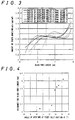
- Fig.3 shows a relation of a toner mass per unit area ( m/a ) on the developing roller 21 versus a free length of the blade 25 (the length l in Fig.2) according to the blade structure A.
- the blade 25 can maintain the toner mass per unit area m/a in the range of between 0.8 and 1.0 mg/cm 2 when the free length l of the blade 25 is in the range of between 5.85 and 7.55 mm.
- a setting allowance for the free length l that is an allowance for the setting position of the blade 25 is 1.7 mm.
- the angle of aperture ⁇ formed between the tilt angle ⁇ of the slant face 25a formed at the tip end of the blade 25 and the angle ⁇ is set to a predetermined value or larger, the range of the allowance for setting of the blade 25 may be widened considerably, which gives leeway to the precision of mounting the blade and facilitates the mounting operation.
- the blade 25 of the aforementioned structure A is pressed against the developing roller such a diameter.
- Fig.3 also shows a relation of a toner mass per unit area ( m/a ) on the developing roller 21 versus a free length of the blade 25 of this case.
- the blade 25 can maintain the toner mass per unit area m/a in the range of between 0.8 and 1.0 mg/cm 2 when the free length l of the blade is in the range of between 6.1 and 7.5 mm.
- the setting allowance of the free length is increased as large as 1.4 mm.
- the allowance for the setting position of the blade 25 varies as the diameter of the developing roller 21 varies. It is further understood that the allowance for the setting position of the blade 25 is increased by ensuring the angle of aperture ⁇ according to the invention.
- Table 1 shows the results obtained when structures A to E of the blade 25, and various diameters of the developing roller 21 are used.
- Radius R of developing roller (mm) ⁇ (°) Blade structure Tilt angle ⁇ (°) Angle of aperture ⁇ at toner inlet (°) Allowance for free length(°) 27 4 A 9.5 13.5 1.7 34 3.4 A 9.5 12.9 1.4 34 3.4 B 7.1 10.5 0.2 34 3.4 C 9.0 12.4 0.4 34 3.4 D 9.8 13.2 1.6 34 3.4 E 10.8 14.2 2.1
- the angle of aperture ⁇ is set at 13.5° or more.
- the nip width w between the blade 25 and the developing roller 21 varies depending upon the elasticity of the developing roller 21.
- an adequate allowance for the setting position of the blade 25 for ensuring a desired toner mass per unit area can be achieved. This contributes to an increased allowance for the free length l in fabricating the blade 25. As a result, not only fabrication of the blade is facilitated, but also allowance for mounting the blade so as to be pressed against the developing roller 21 is increased, so that mounting of the blade is easily executed.
- Example 2 is intended to examine effects of the invention based on the thickness of the blade.
- Example 2 was carried out using the same structure of blade as that of Example 1 except that the thickness of the member constituting the blade 25 is set at 0.3 mm or more.
- the thickness of the member constituting such as the blade 25 with the structure A of Example 1 is set at 0.2 mm or less, the warp resulting from the distortion due to the bending process was limited to 5 mm or less with respect to the overall width of the blade. Accordingly, when the blade was employed with being fixed to the actual developing tank 20 and being pressed against the developing roller 21, a preferable toner layer and a uniform toner mass per unit area are attained.
- Example 3 is intended to examine effects based on selections of materials for the blade 25.
- Example 3 blades of the structure of Example 1 were formed of SUS 301-CSP of JIS G 4313 subjected to a temper of 3/4H, H or EH, SUS 304-CSP subjected to a temper of 3/4H or H, and the like.
- the slang face 25a when formed at the tip end of the blade 25 by bending process, was formed with high precision regarding the shape thereof.
- the straightness of the bent portion of the blade 25 was improved so that a favorable toner layer was formed across the overall axial area of the developing roller 21.
- Fig.5 is a schematic diagram showing a relation between a rolling direction of a thin-sheet material and a bending direction of the same when the slant face of the tip end of the blade 25 was formed by mechanical bending.
- the bending process is preferably carried out so that the bend line 25b crosses with the rolling direction of the thin-sheet material at right angles, as shown in Fig.5.
- the straightness of the blade 25 at the abutting portion with the developing roller 21 was improved and the toner layer was preferably formed across the overall axial area of the developing roller 21, compared to the case where the material was not subjected to the TA treatment.
- Example 4 is intended to examine effects of the invention when the slant face 25a is formed at the tip end of the blade 25 in the configuration of Example 1 by a mechanical bending process.
- Fig.6 shows molds employed in a bending process for forming the slant face 25a of the blade 25.
- Molds 30 of Fig. 6, on which a blade member 250 to be formed into the blade 25 is placed, have slant portions adapted to the slant face 25a.
- the molds 30 are composed of: a punching mold 31 provided with a projection 31a at the position corresponding to a bend portion of the blade, the projection 3a having a height about 0.01 to 0.02 mm; and a die mold 32 to be pressed from above.
- the slant face 25a of the blade 25 is formed by sandwiching the blade member 250 between the punching mold 31 and the die mold 32, and thereafter applying a pressure from above the die mold 32 for press working. At the same time, the blade member 250 is cut into a predetermined length by a shearing mold 33, thereby obtaining the blade 25 of the predetermined length.
- the projection 31a of the punching mold 31 pushes the back side of the blade member 250 at the bend portion thereof, so that a spring-back occurring in the bending process is prevented, as well as a shape of the bent portion of the die 32 (shape of the slant face) may be precisely transferred to the blade member 250.
- This bending process did not produce cracks in the bend portion of the blade or particularly on a side thereof abutting with the developing roller 21.
- the bend portion of the blade 25 is formed with a higher precision compared to the case using molds excluding a projection and a smooth bend surface is obtained.
- the blade 25 thus obtained enabled formation of a more preferable toner layer.
- the slant face 25a was formed at the tip end of the blade 25 by a mechanical bending process of different method from that of Example 4. After the formation of the slant face 25a, the side of the bend portion on which the blade abuts with the developing roller 21 was subjected to a grinding process, thereby obtaining a smooth bend surface. Using this blade, a preferable toner layer was formed.
- the grinding process was carried out in the following steps: roughly grinding the surface with a sand paper of #300 to #450, further grinding the surface with a sand paper of #600 to #1200 and finishing the surface with an emery paper of #2000 to #5000 or a cloth applied with a compound containing alumina.
- Example 6 is intended to examine a configuration which prevents toner from being fused to the surface on which the blade 25 abuts with the developing roller 21 and causing formation of nonuniform toner layer during an extended period of time of use, and effects attained by the configuration.
- the blade 25 of Example 6 had a similar configuration to that of Example 1 and was fabricated in such a manner that following to the formation of the slant face 25a in the blade 25 by the mechanical bending process, an alumite-treated aluminum foil piece 251 is stuck onto the surface involving the slant face 25a and the surface where the blade 25 contacts with the developing roller 21 with a conductive adhesive, as shown in Fig. 7.
- the slant face 25a of the blade 25 was defined by an aluminum tip 252 which was formed by die casting and the surface thereof was alumite-treated. Thereafter, the tip 252 was stuck to a blade member 253 formed of a 0.25 mm-thick phosphor bronze C5210 by the use of a conductive adhesive and thus was obtained the blade 25 shown in Fig.8.
- the tip 252 defined the contact surface with the developing roller 21, offering the similar effect to that of the blade shown in Fig.7.
- the slant face 25a of the blade 25 was formed particularly by bending and consideration was given to reduce influence of distortion caused by a residual stress. Further, the alumite-treated member was used for preventing the toner from fusing to the blade surface 25 in contacting relation with the developing roller 21. A process for forming a member in which a slant face is formed without such bending process and to which alumite-treatment is executed will be described in Example 7.
- the blade of Example 7 has the similar configuration as that of Example 1 except that the slant face 25a at the tip end of the blade 25 is not formed by bending process. Instead, as shown in Fig. 9, a step 25c is formed at a tip end of a blade member 254, and a metal foil piece 255 is stuck so as to cover the step 25c for forming the slant face 25a, thereby forming the blade 25.
- the blade member 254 is formed of a 0.1 mm-thick SUS304 steel sheet and is subject to half-etching to remove a portion on one side thereof in abutment relation with the developing roller 21, the portion having a longitudinal length of about 300 ⁇ m from the tip end of the blade member and a depth of about 50 ⁇ m. Subsequently, the 0.05 mm-thick phosphor bronze foil piece 255 is stuck onto the tip end portion with a conductive adhesive.
- the slant face 25a is not formed by a mechanical bending process in the case of the blade 25 thus fabricated, the slant face 25a having nearly constant tilt angle ⁇ across the overall width of the blade and not causing a warp was achieved. Thus the forming precision was ensured in a simpler manner.
- the blade 25 shown in Fig. 9 can eliminate the disadvantage which may occur in employing a mechanical bending process that the tilt angle is influenced by distortion due to a residual stress depending on thickness or material of the blade member 254.
- the method for forming the step 25c at the blade member 254 is not limited to that illustrated in Fig.9.
- the step 25c may be obtained by sticking (laminating) thin sheets 256, 257, which are two blade members with different lengths of tip end, to each other.
- two thin-sheets 256, 257 having a thickness of 0.05 mm may be stuck to each other.
- a depth of the step 25c may readily be determined by controlling the thickness of the blade member 256.
- the forming precision with respect to a longitudinal length of the step 25a may be readily achieved by bonding or welding such as laser spot welding the members together via a positioning hole.
- an edge (tip end) of the shorter blade member 256 may be used as a reference line and the edge may be fit to a die to cut off an end portion of the longer blade member 257 to a desired length, such as 300 ⁇ m, thereby to form a desired step.
- a desired length such as 300 ⁇ m
- the 0.05 mm-thick metal foil piece such as phosphor bronze foil piece 258 may be stuck to the resultant blade member with the conductive adhesive thereby to fabricate the blade 25 formed with the slant face 25a.
- the predetermined tilt angle ⁇ of the slant face 25a is ensured, with the result that a sufficient setting freedom in mounting the blade 25 to the developing tank 20 is ensured, as well as the predetermined toner mass per unit area and a uniform toner layer are ensured.
- the slant face 25a may be uniformly formed across the overall width of the blade 25, so that the forming precision thereof further increases.
- the metal foil pieces 255, 258 stuck so as to cover the steps 25c shown in Figs.9 and 10 preferably have a thickness of 0.05 mm or less. If the metal foil piece 255 or the like has a thickness of 0.1 mm or more, the metal foil piece 255 or the like will not sufficiently deformed when it is stuck to the blade member, so that the slant face 25a with a smoothness cannot be obtained.
- the metal foil pieces 255, 258 stuck to the step 25c may preferably be alumite-treated foil pieces such as a 0.02 mm-thick aluminum foil piece on which a 0.02 mm-thick alumite layer is formed.
- a metal foil piece presents an improved resistance to toner fusion, as described in Example 6.
Applications Claiming Priority (2)
| Application Number | Priority Date | Filing Date | Title |
|---|---|---|---|
| JP33539497A JP3316437B2 (ja) | 1997-12-05 | 1997-12-05 | 一成分トナーの現像装置 |
| JP33539497 | 1997-12-05 |
Publications (3)
| Publication Number | Publication Date |
|---|---|
| EP0921445A2 true EP0921445A2 (de) | 1999-06-09 |
| EP0921445A3 EP0921445A3 (de) | 2000-07-12 |
| EP0921445B1 EP0921445B1 (de) | 2004-09-15 |
Family
ID=18288059
Family Applications (1)
| Application Number | Title | Priority Date | Filing Date |
|---|---|---|---|
| EP98123182A Expired - Lifetime EP0921445B1 (de) | 1997-12-05 | 1998-12-04 | Einkomponententoner verwendende Entwicklungsvorrichtung |
Country Status (5)
| Country | Link |
|---|---|
| US (1) | US6064463A (de) |
| EP (1) | EP0921445B1 (de) |
| JP (1) | JP3316437B2 (de) |
| CN (1) | CN1114133C (de) |
| DE (1) | DE69826220T2 (de) |
Cited By (2)
| Publication number | Priority date | Publication date | Assignee | Title |
|---|---|---|---|---|
| EP0962835A2 (de) * | 1998-06-02 | 1999-12-08 | Sharp Kabushiki Kaisha | Entwicklungsvorrichtung unter Verwendung eines Einkomponentenentwicklers und Blatt dafür |
| EP1146400A2 (de) * | 2000-04-13 | 2001-10-17 | Canon Kabushiki Kaisha | Entwicklungsgerät und Zusammenbauverfahren dafür |
Families Citing this family (20)
| Publication number | Priority date | Publication date | Assignee | Title |
|---|---|---|---|---|
| JP3919381B2 (ja) * | 1999-05-14 | 2007-05-23 | キヤノン株式会社 | 現像装置、現像カートリッジ、プロセスカートリッジおよび画像形成装置 |
| JP3519044B2 (ja) | 1999-12-28 | 2004-04-12 | シャープ株式会社 | 現像装置 |
| JP2001281985A (ja) | 2000-03-30 | 2001-10-10 | Sharp Corp | 現像装置 |
| KR100389878B1 (en) * | 2001-12-10 | 2003-07-04 | Samsung Electronics Co Ltd | Member for regulating toner layer and developing device using the same |
| JP2004177522A (ja) * | 2002-11-25 | 2004-06-24 | Ricoh Co Ltd | 現像剤規制部材、現像装置及び画像形成装置 |
| CN1318923C (zh) * | 2002-09-20 | 2007-05-30 | 株式会社理光 | 显影剂限制部件,显影装置,处理卡盒及图像形成装置 |
| JP2004206070A (ja) | 2002-10-31 | 2004-07-22 | Hitachi Ltd | 電子写真装置 |
| JP4482296B2 (ja) | 2002-10-31 | 2010-06-16 | 株式会社リコー | 電子写真装置 |
| KR100520932B1 (ko) * | 2003-11-24 | 2005-10-17 | 삼성전자주식회사 | 화상형성장치의 토너층 규제 블레이드 및 이를 채용한현상유닛 |
| JP2007106080A (ja) * | 2005-10-17 | 2007-04-26 | Bridgestone Corp | 現像剤量規制ブレード形成用金型、および、それによって形成される現像剤量規制ブレード |
| KR100716284B1 (ko) * | 2006-02-03 | 2007-05-09 | 삼성전자주식회사 | 현상카트리지 및 이를 포함하는 화상형성장치 |
| US7657213B2 (en) * | 2006-05-15 | 2010-02-02 | Lexmark International, Inc. | Doctor blade with tangential working tip |
| JP5151302B2 (ja) * | 2007-08-06 | 2013-02-27 | 株式会社リコー | 現像装置、プロセスカートリッジ、画像形成装置 |
| JP4833259B2 (ja) * | 2008-06-30 | 2011-12-07 | 株式会社沖データ | 現像装置及び画像形成装置 |
| US7937030B2 (en) | 2008-06-30 | 2011-05-03 | Oki Data Corporation | Developing unit and image forming apparatus |
| US8045882B2 (en) * | 2008-10-08 | 2011-10-25 | Jesse Delcamp | Self-sealing process roller |
| JP4932014B2 (ja) * | 2010-03-01 | 2012-05-16 | シャープ株式会社 | 現像装置および画像形成装置 |
| JP5755175B2 (ja) * | 2012-04-18 | 2015-07-29 | キヤノン株式会社 | 現像装置、プロセスカートリッジ |
| JP6091080B2 (ja) * | 2012-04-26 | 2017-03-08 | キヤノン株式会社 | 現像装置、カートリッジ、及び画像形成装置 |
| US10036976B2 (en) | 2015-12-17 | 2018-07-31 | Ricoh Company, Ltd. | Developing device, and image forming apparatus and process unit incorporating same |
Citations (4)
| Publication number | Priority date | Publication date | Assignee | Title |
|---|---|---|---|---|
| JPH03256079A (ja) * | 1990-03-06 | 1991-11-14 | Canon Inc | 現像装置 |
| JPH08211728A (ja) * | 1995-02-02 | 1996-08-20 | Canon Inc | 現像装置 |
| US5552867A (en) * | 1993-08-27 | 1996-09-03 | Minolta Co., Ltd. | Toner regulating blade having a bevelled edge |
| JPH08328298A (ja) * | 1995-05-31 | 1996-12-13 | Canon Inc | 静電荷像現像用トナー及び画像形成方法 |
Family Cites Families (5)
| Publication number | Priority date | Publication date | Assignee | Title |
|---|---|---|---|---|
| JPS59232363A (ja) * | 1983-06-15 | 1984-12-27 | Canon Inc | 現像方法 |
| JPS6015068A (ja) * | 1983-07-07 | 1985-01-25 | Toshiba Corp | ア−ク溶接方法 |
| JPH05224521A (ja) * | 1992-02-13 | 1993-09-03 | Nec Corp | 現像装置及び画像形成装置 |
| JP3223688B2 (ja) * | 1994-02-28 | 2001-10-29 | ミノルタ株式会社 | ブレード |
| JP3223657B2 (ja) * | 1993-08-27 | 2001-10-29 | ミノルタ株式会社 | ブレード |
-
1997
- 1997-12-05 JP JP33539497A patent/JP3316437B2/ja not_active Expired - Lifetime
-
1998
- 1998-12-03 US US09/204,811 patent/US6064463A/en not_active Expired - Lifetime
- 1998-12-04 EP EP98123182A patent/EP0921445B1/de not_active Expired - Lifetime
- 1998-12-04 DE DE69826220T patent/DE69826220T2/de not_active Expired - Lifetime
- 1998-12-05 CN CN98127177.4A patent/CN1114133C/zh not_active Expired - Lifetime
Patent Citations (4)
| Publication number | Priority date | Publication date | Assignee | Title |
|---|---|---|---|---|
| JPH03256079A (ja) * | 1990-03-06 | 1991-11-14 | Canon Inc | 現像装置 |
| US5552867A (en) * | 1993-08-27 | 1996-09-03 | Minolta Co., Ltd. | Toner regulating blade having a bevelled edge |
| JPH08211728A (ja) * | 1995-02-02 | 1996-08-20 | Canon Inc | 現像装置 |
| JPH08328298A (ja) * | 1995-05-31 | 1996-12-13 | Canon Inc | 静電荷像現像用トナー及び画像形成方法 |
Non-Patent Citations (3)
| Title |
|---|
| PATENT ABSTRACTS OF JAPAN vol. 016, no. 058 (P-1311), 13 February 1992 (1992-02-13) & JP 03 256079 A (CANON INC), 14 November 1991 (1991-11-14) * |
| PATENT ABSTRACTS OF JAPAN vol. 1996, no. 12, 26 December 1996 (1996-12-26) & JP 08 211728 A (CANON INC), 20 August 1996 (1996-08-20) * |
| PATENT ABSTRACTS OF JAPAN vol. 1997, no. 04, 30 April 1997 (1997-04-30) & JP 08 328298 A (CANON INC), 13 December 1996 (1996-12-13) * |
Cited By (5)
| Publication number | Priority date | Publication date | Assignee | Title |
|---|---|---|---|---|
| EP0962835A2 (de) * | 1998-06-02 | 1999-12-08 | Sharp Kabushiki Kaisha | Entwicklungsvorrichtung unter Verwendung eines Einkomponentenentwicklers und Blatt dafür |
| EP0962835A3 (de) * | 1998-06-02 | 2001-02-07 | Sharp Kabushiki Kaisha | Entwicklungsvorrichtung unter Verwendung eines Einkomponentenentwicklers und Blatt dafür |
| US6330416B1 (en) | 1998-06-02 | 2001-12-11 | Sharp Kabushiki Kaisha | Blade for a developing device and methods of making the same |
| EP1146400A2 (de) * | 2000-04-13 | 2001-10-17 | Canon Kabushiki Kaisha | Entwicklungsgerät und Zusammenbauverfahren dafür |
| EP1146400A3 (de) * | 2000-04-13 | 2005-08-03 | Canon Kabushiki Kaisha | Entwicklungsgerät und Zusammenbauverfahren dafür |
Also Published As
| Publication number | Publication date |
|---|---|
| EP0921445B1 (de) | 2004-09-15 |
| US6064463A (en) | 2000-05-16 |
| JP3316437B2 (ja) | 2002-08-19 |
| EP0921445A3 (de) | 2000-07-12 |
| CN1225458A (zh) | 1999-08-11 |
| DE69826220D1 (de) | 2004-10-21 |
| JPH11167278A (ja) | 1999-06-22 |
| CN1114133C (zh) | 2003-07-09 |
| DE69826220T2 (de) | 2005-11-24 |
Similar Documents
| Publication | Publication Date | Title |
|---|---|---|
| EP0921445B1 (de) | Einkomponententoner verwendende Entwicklungsvorrichtung | |
| JP3103704B2 (ja) | 現像装置 | |
| US5311264A (en) | Developing apparatus for developing electrostatic latent image using one component developer | |
| EP1191403B1 (de) | Aufladungsrolle für ein Bilderzeugungsgerät | |
| US5324884A (en) | Developing device having first and second toner supply means with an electric field generated therebetween | |
| EP1372045A2 (de) | Entwicklungsgerät mit Entwicklerträger mit Nuten und dieses verwendender Bildformungsapparat | |
| EP0939349B1 (de) | Entwicklungsvorrichtung, die einen Einkomponenten-Toner verwendet | |
| EP1818731A1 (de) | Entwicklungsvorrichtung, Prozesskartusche und Bilderzeugungsvorrichtung | |
| EP0962835B1 (de) | Entwicklungsvorrichtung unter Verwendung eines Einkomponentenentwicklers und in der Vorrichtung enthaltene elastische Klinge | |
| EP0987603B1 (de) | Elektrophotographisches photoempfindliches Element und elektrophotographisches Gerät | |
| US7672619B2 (en) | Wire bar, method of manufacturing wire bar, and image forming apparatus | |
| EP1507175B1 (de) | Entwicklungsregelungsteil und Entwicklungsgerät | |
| EP0636950B1 (de) | Entwicklungsgerät mit einer sich drehenden Entwicklerzufuhreinheit einer Entwicklerträgereinheit | |
| US6282394B1 (en) | Toner developing device for an image forming apparatus | |
| US6882818B2 (en) | Image forming apparatus having a development apparatus forming a magnetic brush separated from a latent image carrier outside a development area | |
| JP3136288B2 (ja) | 現像装置 | |
| JP2008033020A (ja) | 現像装置および画像形成装置 | |
| JP2629198B2 (ja) | 現像装置 | |
| JPH0375767A (ja) | 電子写真装置の現像器 | |
| JP3148964B2 (ja) | 電子写真装置 | |
| JPH02247667A (ja) | トナー現像装置 | |
| JP2001034058A (ja) | 画像形成方法およびこれを用いた画像形成装置 | |
| JP2000338771A (ja) | 現像方法 | |
| JP2002328524A (ja) | 現像装置 | |
| JPH0792798A (ja) | 現像装置およびこの現像装置を備える画像形成装置 |
Legal Events
| Date | Code | Title | Description |
|---|---|---|---|
| PUAI | Public reference made under article 153(3) epc to a published international application that has entered the european phase |
Free format text: ORIGINAL CODE: 0009012 |
|
| AK | Designated contracting states |
Kind code of ref document: A2 Designated state(s): DE FR GB |
|
| AX | Request for extension of the european patent |
Free format text: AL;LT;LV;MK;RO;SI |
|
| PUAL | Search report despatched |
Free format text: ORIGINAL CODE: 0009013 |
|
| AK | Designated contracting states |
Kind code of ref document: A3 Designated state(s): AT BE CH CY DE DK ES FI FR GB GR IE IT LI LU MC NL PT SE |
|
| AX | Request for extension of the european patent |
Free format text: AL;LT;LV;MK;RO;SI |
|
| 17P | Request for examination filed |
Effective date: 20001025 |
|
| AKX | Designation fees paid |
Free format text: DE FR GB |
|
| 17Q | First examination report despatched |
Effective date: 20030321 |
|
| GRAP | Despatch of communication of intention to grant a patent |
Free format text: ORIGINAL CODE: EPIDOSNIGR1 |
|
| RTI1 | Title (correction) |
Free format text: DEVELOPING APPARATUS USING ONE-COMPONENT TONER |
|
| GRAS | Grant fee paid |
Free format text: ORIGINAL CODE: EPIDOSNIGR3 |
|
| GRAA | (expected) grant |
Free format text: ORIGINAL CODE: 0009210 |
|
| RIN1 | Information on inventor provided before grant (corrected) |
Inventor name: TATSUMI, HIROSHI Inventor name: MATSUYAMA, KAZUHIRO Inventor name: YASUDA, KEIJI Inventor name: AZUMA, NOBUYUKI Inventor name: INOUE, ATSUSHI Inventor name: IWAMATSU, TADASHI Inventor name: TAKAYA, TOSHIHIKO Inventor name: YAMANAKA, TAKAYUKI Inventor name: YAMADA, MASANORI |
|
| AK | Designated contracting states |
Kind code of ref document: B1 Designated state(s): DE FR GB |
|
| REG | Reference to a national code |
Ref country code: GB Ref legal event code: FG4D |
|
| REF | Corresponds to: |
Ref document number: 69826220 Country of ref document: DE Date of ref document: 20041021 Kind code of ref document: P |
|
| ET | Fr: translation filed | ||
| PLBE | No opposition filed within time limit |
Free format text: ORIGINAL CODE: 0009261 |
|
| STAA | Information on the status of an ep patent application or granted ep patent |
Free format text: STATUS: NO OPPOSITION FILED WITHIN TIME LIMIT |
|
| 26N | No opposition filed |
Effective date: 20050616 |
|
| REG | Reference to a national code |
Ref country code: FR Ref legal event code: PLFP Year of fee payment: 18 |
|
| REG | Reference to a national code |
Ref country code: FR Ref legal event code: PLFP Year of fee payment: 19 |
|
| REG | Reference to a national code |
Ref country code: FR Ref legal event code: PLFP Year of fee payment: 20 |
|
| PGFP | Annual fee paid to national office [announced via postgrant information from national office to epo] |
Ref country code: FR Payment date: 20171221 Year of fee payment: 20 Ref country code: DE Payment date: 20171211 Year of fee payment: 20 |
|
| PGFP | Annual fee paid to national office [announced via postgrant information from national office to epo] |
Ref country code: GB Payment date: 20171221 Year of fee payment: 20 |
|
| REG | Reference to a national code |
Ref country code: DE Ref legal event code: R071 Ref document number: 69826220 Country of ref document: DE |
|
| REG | Reference to a national code |
Ref country code: GB Ref legal event code: PE20 Expiry date: 20181203 |
|
| PG25 | Lapsed in a contracting state [announced via postgrant information from national office to epo] |
Ref country code: GB Free format text: LAPSE BECAUSE OF EXPIRATION OF PROTECTION Effective date: 20181203 |