EP0920108A2 - Kältemittelkompressor - Google Patents
Kältemittelkompressor Download PDFInfo
- Publication number
- EP0920108A2 EP0920108A2 EP98122513A EP98122513A EP0920108A2 EP 0920108 A2 EP0920108 A2 EP 0920108A2 EP 98122513 A EP98122513 A EP 98122513A EP 98122513 A EP98122513 A EP 98122513A EP 0920108 A2 EP0920108 A2 EP 0920108A2
- Authority
- EP
- European Patent Office
- Prior art keywords
- clipboard
- terminal box
- refrigerant compressor
- compressor according
- terminal
- Prior art date
- Legal status (The legal status is an assumption and is not a legal conclusion. Google has not performed a legal analysis and makes no representation as to the accuracy of the status listed.)
- Granted
Links
Images


Classifications
-
- H—ELECTRICITY
- H02—GENERATION; CONVERSION OR DISTRIBUTION OF ELECTRIC POWER
- H02K—DYNAMO-ELECTRIC MACHINES
- H02K5/00—Casings; Enclosures; Supports
- H02K5/04—Casings or enclosures characterised by the shape, form or construction thereof
- H02K5/22—Auxiliary parts of casings not covered by groups H02K5/06-H02K5/20, e.g. shaped to form connection boxes or terminal boxes
- H02K5/225—Terminal boxes or connection arrangements
-
- F—MECHANICAL ENGINEERING; LIGHTING; HEATING; WEAPONS; BLASTING
- F25—REFRIGERATION OR COOLING; COMBINED HEATING AND REFRIGERATION SYSTEMS; HEAT PUMP SYSTEMS; MANUFACTURE OR STORAGE OF ICE; LIQUEFACTION SOLIDIFICATION OF GASES
- F25B—REFRIGERATION MACHINES, PLANTS OR SYSTEMS; COMBINED HEATING AND REFRIGERATION SYSTEMS; HEAT PUMP SYSTEMS
- F25B31/00—Compressor arrangements
- F25B31/02—Compressor arrangements of motor-compressor units
-
- H—ELECTRICITY
- H02—GENERATION; CONVERSION OR DISTRIBUTION OF ELECTRIC POWER
- H02K—DYNAMO-ELECTRIC MACHINES
- H02K11/00—Structural association of dynamo-electric machines with electric components or with devices for shielding, monitoring or protection
Definitions
- the invention relates to a refrigerant compressor, comprising a compressor housing in which a refrigerant compressing Unit and an electric motor driving this arranged are, as well as a terminal box sitting on the housing.
- Such refrigerant compressors are from the prior art Technology known.
- the invention has for its object a refrigerant compressor to improve the generic type such that this can be produced as inexpensively as possible.
- the solution according to the invention has the great advantage that with such a terminal box the electrical connection is easier to manufacture because with the installation of the Terminal box already includes the clipboard for this intended applicable place is mounted.
- Terminals preferably for connecting winding taps serve the electric motor. This is preferable six terminals are provided.
- the clipboard integrally molded onto the terminal box can, for example, following a side wall of the same be arranged.
- the side walls are preferably longitudinal side walls of the Terminal box so that the clipboard is parallel to the Extends transverse side walls.
- a particularly favorable solution provides that a bottom of the Terminal box with at least one on the side of the clipboard lying breakthrough for performing electrical Lines is provided. It is particularly favorable if the Bottom on both sides of the clipboard in particular between this and the side walls running parallel to this, is provided with breakthroughs.
- connection options on the underside can, it is preferably provided that a bottom of the Terminal box in the area of the clipboard with a die Underside of the clipboard making accessible recess is provided.
- this support wall extends between the Bottom and the clipboard and thus both stiffened relatively to each other.
- the retaining wall could in principle be at any point on the Clipboards may be provided.
- To connect to The retaining wall is preferably not to hinder the clipboard arranged on one side of the clipboard.
- the clipboard can be designed, for example, that only on its top, lines to the individual Terminals are connectable.
- the clipboard is designed so that lines on the top and bottom of which can be connected.
- the clipboard could, for example, be designed such that it separate on the top and bottom Has terminals. Can be particularly cheap however, those required to operate an electric motor Realize connection variants when the clipboard with terminals for the electrical connections is provided, which is passed through the clipboard are and on which both on a top and on a bottom lines are connectable.
- Such terminals of the clipboard can be in different Way be trained.
- a particularly advantageous solution provides that the clipboard is provided with screwable terminals as with these particularly secure connections can be made.
- connection terminals are designed as pins.
- the clipboard between each other adjacent terminals with path-extending elements is provided.
- Such path-extending elements can both indentations and surveys based on the Surface of the clipboard are provided.
- terminal box is molded in one piece Terminal block is provided, so that also to provide more Connections, for example additional connections to the clipboard, no additional element built into the terminal box must be, but also already the integral as Part of the terminal box designed terminal block can be used.
- This terminal strip preferably runs parallel to one Long side wall of the terminal box and is particularly in the Connection to this molded onto the terminal box.
- a particularly expedient solution to this seal is seen here before that through a in a groove in the bottom of the terminal box introduced sealing compound, preferably a foamed mass is formed.
- Refrigerant compressor comprises a compressor housing 12, in which a cold compressing unit 14 is arranged which is also via a compressor housing 12 arranged electric motor not visible in the drawing is drivable.
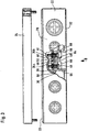
- This terminal box 20 comprises, as shown in Fig. 2 to 4, a lower housing part 22, the upper housing opening 23 can be closed with a lid 24.
- the lower housing part 22 has two longitudinal side walls 26a, b and two transverse side walls 28a, b, each parallel to each other.
- the clipboard 30 carries three pairs of electrical ones Terminals serving threaded sleeves 34a, b, 36a, b, 38a, b the in the direction of the extension of the transverse side walls 28a, b are arranged side by side, with each of the Pairs 34a, b, 36a, b and 38a, b the two individual threaded sleeves 34a, 34b, 36a, 36b and 38a, 38b towards the Extension of the longitudinal side walls 28a, b spaced apart are.
- the distances between the threaded sleeves are preferred within a pair 34a, 34b, 36a, 36b and 38a, 38b as well the distances between each successive Pairs 34a, b 36a, b and 38a, b in the direction of the transverse side walls 28a, b seen approximately the same size.
- the threaded sleeves 34b, 36b and 38b with the a first set of winding taps Lines 42a, 42b and 42c connected while the threaded sleeves 34a, 36a, 38a with a second set of Lines 44a, 44b, 44c representing winding taps are connected.
- the second set of electrical is also expedient Lines 44a, 44b, 44c via an underside 40 of the Clipboards 30 led to the threaded sleeves 34a, 36a, 38a and via head screws screwed into the threaded sleeves 34a, 36a, 38a 45 electrically connected to them.
- connection of the winding taps is then via additionally connectable with the threaded pins 41 Bridges possible.
- V-shaped web 60 lie with their open side on a support wall 56, which is on one side 58 of the Terminal boards 30 between the bottom 32 and the clipboard 30 and extends between the longitudinal side walls 26a, b and preferably runs parallel to the transverse side wall 28b.
- the Support wall 56 is preferably also in one piece the longitudinal side walls 26a, b, the bottom 32 and the clipboard 30 molded.
- V-shaped webs have 60 then with their tips 62 in the direction of the support wall 56 path.
- the webs 64 also on the bottom 40 in the direction of Floor 32 extend.
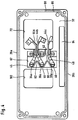
- the floor 32 is in the area of the Clipboards 30 provided with an access opening 67 which approximately one corresponding to the extension of the clipboard 30 Has expansion.
- An opening 68 is provided in the terminal boards 30 and the bottom 32, through which the lines 44a to c from the threaded sleeves 34a, 36a and 38a over the bottom 40 of the clipboard 30 insertable into an interior 70 of the terminal box 20 are.
- Terminal block 80 the total with 20 terminal box designated as a whole designated 80 Terminal block provided, which is a series of Has terminal elements 82. Also the terminal block 80 as The carrier of the clamping elements 82 is in one piece on the longitudinal side wall 26b formed and lies between this and the Clipboard 30, which is integral to the housing molded terminal block 80 connects. Terminal block 80 has one parallel to the floor 32 with a terminal strip wall 84 extending to the longitudinal side wall 26b and parallel to the transverse side walls 28a, b extending terminal strip transverse walls 86a, b provided Terminal block body 88, which still has the terminal block walls 84 and 86 final terminal strip cover 90 on which the individual terminal elements 82 sit.
- the entire terminal block body 88 with the terminal block cover 90 and the terminal block walls 84 and 86 is in one piece on the Lower housing part 22 is formed so that starting from Floor 32 between the longitudinal side wall 26b and the terminal strip wall 84 and the terminal block transverse walls 86a and 86b and the terminal strip cover 90 forms a cavity 94.
- a groove 96 is provided, in which a foamed seal 98 is introduced, which is close to the Long side walls 26a, b and the transverse side walls 28a, b around all openings in the bottom 32 and enclosing them runs around and on a bearing surface 100 of the compressor housing 12 adjacent a tight seal between the Bottom 32 of the lower housing part 22 and the compressor housing 12 forms.
Landscapes
- Engineering & Computer Science (AREA)
- Power Engineering (AREA)
- Compressor (AREA)
Abstract
Description
- Fig. 1
- eine schematische Ansicht eines erfindungsgemäßen Kältemittelkompressors;
- Fig. 2
- eine Draufsicht auf einen Klemmenkasten gemäß der erfindungsgemäßen Lösung mit teilweise aufgebrochenem Deckel;
- Fig. 3
- eine Seitenansicht des Klemmenkastens in Richtung des Pfeils A in Fig. 1 mit teilweise aufgebrochener Seitenwand und abgehobenem Deckel und
- Fig. 4
- eine Ansicht des Klemmenkastens von unten in Richtung des Pfeils B in Fig. 3.
Claims (17)
- Kältemittelkompressor, umfassend ein Kompressorgehäuse, in welchem eine kältemittelkomprimierende Einheit und ein diese antreibender Elektromotor angeordnet sind, sowie einen an dem Kompressorgehäuse sitzenden Klemmenkasten,
dadurch gekennzeichnet, daß der Klemmenkasten (20) ein einstückig an diesen angeformtes und in einem Innenraum (70) desselben angeordnetes Klemmbrett (30) aufweist. - Kältemittelkompressor nach Anspruch 1, dadurch gekennzeichnet, daß das Klemmbrett (30) sich in einem mittigen Bereich des Klemmenkastens (20) zwischen zwei Seitenwänden (26a, b) erstreckt.
- Kältemittelkompressor nach Anspruch 2, dadurch gekennzeichnet, daß sich das Klemmbrett (30) zwischen Längsseitenwänden (26a, b) und parallel zu Querseitenwänden (28a, b) erstreckt.
- Kältemittelkompressor nach einem der voranstehenden Ansprüche, dadurch gekennzeichnet, daß das Klemmbrett (30) im Abstand über einem Boden (32) des Klemmenkastens (20) angeordnet ist.
- Kältemittelkompressor nach einem der voranstehenden Ansprüche, dadurch gekennzeichnet, daß ein Boden (32) des Klemmenkastens (20) mit mindestens einem seitlich des Klemmbretts (30) liegenden Durchbruch (72, 100) versehen ist.
- Kältemittelkompressor nach Anspruch 5, dadurch gekennzeichnet, daß der Klemmenkasten (20) beiderseits des Klemmbretts (30) mit Durchbrüchen (72, 102) versehen ist.
- Kältemittelkompressor nach einem der voranstehenden Ansprüche, dadurch gekennzeichnet, daß ein Boden (32) des Klemmenkastens (20) im Bereich des Klemmbretts (30) mit einer die Unterseite (40) des Klemmbretts (30) zugänglich machenden Ausnehmung (66) versehen ist.
- Kältemittelkompressor nach einem der voranstehenden Ansprüche, dadurch gekennzeichnet, daß im Anschluß an das Klemmbrett (30) eine quer zum Klemmbrett (30) und quer zum Boden (32) des Klemmenkastens (20) verlaufende Stützwand (56) vorgesehen ist.
- Kältemittelkompressor nach Anspruch 8, dadurch gekennzeichnet, daß die Stützwand (56) auf einer Seite des Klemmbretts (30) angeordnet ist.
- Kältemittelkompressor nach einem der voranstehenden Ansprüche, dadurch gekennzeichnet, daß das Klemmbrett so ausgebildet ist, daß Leitungen (42, 44) an dessen Oberseite (39) und dessen Unterseite (40) an Anschlußklemmen des Klemmbretts anschließbar sind.
- Kältemittelkompressor nach Anspruch 10, dadurch gekennzeichnet, daß das Klemmbrett (30) mit Anschlußklemmen (34, 36, 38) versehen ist, welche durch das Klemmbrett (30) hindurchgeführt sind.
- Kältemittelkompressor nach Anspruch 11, dadurch gekennzeichnet, daß das Klemmbrett (30) mit schraubbaren Anschlußklemmen (34, 36, 38) versehen ist.
- Kältemittelkompressor nach einem der voranstehenden Ansprüche, dadurch gekennzeichnet, daß das Klemmbrett (30) zwischen einzelnen einander benachbarten Anschlußklemmen (34, 36, 38) mit wegverlängernden Elementen (46, 48, 50) versehen ist.
- Kältemittelkompressor nach Anspruch 13, dadurch gekennzeichnet, daß die wegverlängernden Elemente (46, 48, 50) als einstückig an das Klemmbrett (30) angeformte Elemente ausgebildet sind.
- Kältemittelkompressor nach einem der voranstehenden Ansprüche, dadurch gekennzeichnet, daß der Klemmenkasten (20) mit einer einstückig in diesen eingeformten Klemmenleiste (80) versehen ist.
- Kältemittelkompressor nach einem der voranstehenden Ansprüche, dadurch gekennzeichnet, daß ein Boden des Klemmenkastens (20) eine fest mit dem Klemmenkasten (20) verbundene umlaufende Dichtung (98) aufweist.
- Kältemittelkompressor nach Anspruch 16, dadurch gekennzeichnet, daß die Dichtung (98) durch eine in eine Nut (96) im Boden (32) des Klemmenkastens (20) eingebrachte Dichtungsmasse ausgebildet ist.
Applications Claiming Priority (2)
| Application Number | Priority Date | Filing Date | Title |
|---|---|---|---|
| DE19752632 | 1997-11-27 | ||
| DE19752632A DE19752632A1 (de) | 1997-11-27 | 1997-11-27 | Kältemittelkompressor |
Publications (3)
| Publication Number | Publication Date |
|---|---|
| EP0920108A2 true EP0920108A2 (de) | 1999-06-02 |
| EP0920108A3 EP0920108A3 (de) | 2001-02-14 |
| EP0920108B1 EP0920108B1 (de) | 2006-10-04 |
Family
ID=7850011
Family Applications (1)
| Application Number | Title | Priority Date | Filing Date |
|---|---|---|---|
| EP98122513A Expired - Lifetime EP0920108B1 (de) | 1997-11-27 | 1998-11-27 | Kältemittelkompressor |
Country Status (3)
| Country | Link |
|---|---|
| EP (1) | EP0920108B1 (de) |
| DE (2) | DE19752632A1 (de) |
| ES (1) | ES2273392T3 (de) |
Family Cites Families (7)
| Publication number | Priority date | Publication date | Assignee | Title |
|---|---|---|---|---|
| DE1889455U (de) * | 1964-01-22 | 1964-03-19 | Continental Elektro Ind Ag | Drehstrommotor fuer kompressorantrieb. |
| IT1141680B (it) * | 1980-11-03 | 1986-10-08 | Necchi Spa | Morsettiera e scatola rele' in motocompressori per apparati frigoriferi |
| IT1259637B (it) * | 1992-03-26 | 1996-03-25 | Dorin Mario Spa | Scatola per contatti di un motore elettrico con morsetteria ricavata di pezzo nella scatola |
| DE4216036A1 (de) * | 1992-05-15 | 1993-11-18 | Sew Eurodrive Gmbh & Co | Motoranschlußblock, insbesondere für Elektromotoren |
| DE4342761C2 (de) * | 1993-12-15 | 1996-04-11 | Modelec Sa | Anschlußgehäuse für einen Elektromotor |
| DE4435510C1 (de) * | 1994-10-04 | 1996-03-07 | Grundfos As | Frequenzumrichtergespeistes Pumpenaggregat |
| EP1077521A3 (de) * | 1996-03-29 | 2002-02-13 | Newage International Limited | Anschlussanordnung |
-
1997
- 1997-11-27 DE DE19752632A patent/DE19752632A1/de not_active Ceased
-
1998
- 1998-11-27 EP EP98122513A patent/EP0920108B1/de not_active Expired - Lifetime
- 1998-11-27 DE DE59813752T patent/DE59813752D1/de not_active Expired - Lifetime
- 1998-11-27 ES ES98122513T patent/ES2273392T3/es not_active Expired - Lifetime
Also Published As
| Publication number | Publication date |
|---|---|
| EP0920108B1 (de) | 2006-10-04 |
| DE59813752D1 (de) | 2006-11-16 |
| ES2273392T3 (es) | 2007-05-01 |
| EP0920108A3 (de) | 2001-02-14 |
| DE19752632A1 (de) | 1999-06-02 |
Similar Documents
| Publication | Publication Date | Title |
|---|---|---|
| DE3812996C2 (de) | ||
| EP1236256B1 (de) | Kabeldurchführung | |
| DE3441297C2 (de) | Elektrischer Verteiler in Blockform, insbesondere für Luft- und Raumfahrt-Anwendungen | |
| DE2930843A1 (de) | Vorrichtung zur verbindung der enden von in einem schutzkanal angeordneten sammelschienen | |
| DE69502668T2 (de) | Stossverbindungsvorrichtung für einen elektrischen Installationskanal | |
| DE3938931C2 (de) | ||
| DE3048497A1 (de) | Querverbinder fuer reihenklemmen | |
| DE2604783C3 (de) | Elektrischer Nockenschalter | |
| DE3817002A1 (de) | Elektromagnetisches schaltgeraet | |
| DE3518109A1 (de) | Unterputzdose | |
| DE2007014C3 (de) | Elektrische Kontaktbuchse | |
| EP0818853B1 (de) | Zündpillen-Steckverbindung | |
| DE4338562C2 (de) | Elektrisches Verbinderbauteil mit gesicherter Abdichtung | |
| DE8132718U1 (de) | Anschlußvorrichtung, insbesondere für Fernmeldeleitungen | |
| DE3017561A1 (de) | Schaltgeraet | |
| EP0123872A1 (de) | Zenerbarriere | |
| DE3150438A1 (de) | Gehaeuse zur aufnahme der zur beschaltung einer magnetspule eines hydraulikventils oder dgl. erforderlichen elektrischen bauteile | |
| EP0920108B1 (de) | Kältemittelkompressor | |
| EP0450397B1 (de) | Abschirmung für Leistungsschalter | |
| DE3641153C2 (de) | ||
| DE3852249T2 (de) | Thermostat. | |
| DE10142195A1 (de) | Steckverbinder mit Isolations-und Dichtungselement | |
| DE3306219C2 (de) | Schalter, insbesondere für Kraftfahrzeuge | |
| DE3503412A1 (de) | Verbinder zum anschliessen eines mehradrigen elektrichen flachkabels an andere schaltungselemente | |
| DE3122611C2 (de) | Verschlußkappe für elektrische Kontaktsysteme |
Legal Events
| Date | Code | Title | Description |
|---|---|---|---|
| PUAI | Public reference made under article 153(3) epc to a published international application that has entered the european phase |
Free format text: ORIGINAL CODE: 0009012 |
|
| AK | Designated contracting states |
Kind code of ref document: A2 Designated state(s): BE DE ES FR GB IT |
|
| AX | Request for extension of the european patent |
Free format text: AL;LT;LV;MK;RO;SI |
|
| PUAL | Search report despatched |
Free format text: ORIGINAL CODE: 0009013 |
|
| AK | Designated contracting states |
Kind code of ref document: A3 Designated state(s): AT BE CH CY DE DK ES FI FR GB GR IE IT LI LU MC NL PT SE |
|
| AX | Request for extension of the european patent |
Free format text: AL;LT;LV;MK;RO;SI |
|
| 17P | Request for examination filed |
Effective date: 20010728 |
|
| AKX | Designation fees paid |
Free format text: BE DE ES FR GB IT |
|
| GRAP | Despatch of communication of intention to grant a patent |
Free format text: ORIGINAL CODE: EPIDOSNIGR1 |
|
| GRAS | Grant fee paid |
Free format text: ORIGINAL CODE: EPIDOSNIGR3 |
|
| GRAA | (expected) grant |
Free format text: ORIGINAL CODE: 0009210 |
|
| AK | Designated contracting states |
Kind code of ref document: B1 Designated state(s): BE DE ES FR GB IT |
|
| PG25 | Lapsed in a contracting state [announced via postgrant information from national office to epo] |
Ref country code: IT Free format text: LAPSE BECAUSE OF FAILURE TO SUBMIT A TRANSLATION OF THE DESCRIPTION OR TO PAY THE FEE WITHIN THE PRE;WARNING: LAPSES OF ITALIAN PATENTS WITH EFFECTIVE DATE BEFORE 2007 MAY HAVE OCCURRED AT ANY TIME BEFORE 2007. THE CORRECT EFFECTIVE DATE MAY BE DIFFERENT FROM THE ONE RECORDED.SCRIBED TIME-LIMIT Effective date: 20061004 |
|
| REG | Reference to a national code |
Ref country code: GB Ref legal event code: FG4D Free format text: NOT ENGLISH |
|
| GBT | Gb: translation of ep patent filed (gb section 77(6)(a)/1977) |
Effective date: 20061018 |
|
| REF | Corresponds to: |
Ref document number: 59813752 Country of ref document: DE Date of ref document: 20061116 Kind code of ref document: P |
|
| ET | Fr: translation filed | ||
| REG | Reference to a national code |
Ref country code: ES Ref legal event code: FG2A Ref document number: 2273392 Country of ref document: ES Kind code of ref document: T3 |
|
| PLBE | No opposition filed within time limit |
Free format text: ORIGINAL CODE: 0009261 |
|
| STAA | Information on the status of an ep patent application or granted ep patent |
Free format text: STATUS: NO OPPOSITION FILED WITHIN TIME LIMIT |
|
| 26N | No opposition filed |
Effective date: 20070705 |
|
| PGFP | Annual fee paid to national office [announced via postgrant information from national office to epo] |
Ref country code: BE Payment date: 20080929 Year of fee payment: 11 |
|
| BERE | Be: lapsed |
Owner name: BITZER KUHLMASCHINENBAU G.M.B.H. Effective date: 20091130 |
|
| PG25 | Lapsed in a contracting state [announced via postgrant information from national office to epo] |
Ref country code: BE Free format text: LAPSE BECAUSE OF NON-PAYMENT OF DUE FEES Effective date: 20091130 |
|
| REG | Reference to a national code |
Ref country code: DE Ref legal event code: R082 Ref document number: 59813752 Country of ref document: DE Representative=s name: HOEGER, STELLRECHT & PARTNER PATENTANWAELTE MB, DE |
|
| REG | Reference to a national code |
Ref country code: FR Ref legal event code: PLFP Year of fee payment: 18 |
|
| REG | Reference to a national code |
Ref country code: FR Ref legal event code: PLFP Year of fee payment: 19 |
|
| REG | Reference to a national code |
Ref country code: FR Ref legal event code: PLFP Year of fee payment: 20 |
|
| PGFP | Annual fee paid to national office [announced via postgrant information from national office to epo] |
Ref country code: FR Payment date: 20171127 Year of fee payment: 20 |
|
| PGFP | Annual fee paid to national office [announced via postgrant information from national office to epo] |
Ref country code: ES Payment date: 20171222 Year of fee payment: 20 Ref country code: IT Payment date: 20171122 Year of fee payment: 20 Ref country code: GB Payment date: 20171130 Year of fee payment: 20 |
|
| PGFP | Annual fee paid to national office [announced via postgrant information from national office to epo] |
Ref country code: DE Payment date: 20180131 Year of fee payment: 20 |
|
| REG | Reference to a national code |
Ref country code: DE Ref legal event code: R071 Ref document number: 59813752 Country of ref document: DE |
|
| REG | Reference to a national code |
Ref country code: GB Ref legal event code: PE20 Expiry date: 20181126 |
|
| PG25 | Lapsed in a contracting state [announced via postgrant information from national office to epo] |
Ref country code: GB Free format text: LAPSE BECAUSE OF EXPIRATION OF PROTECTION Effective date: 20181126 |
|
| REG | Reference to a national code |
Ref country code: ES Ref legal event code: FD2A Effective date: 20200902 |
|
| PG25 | Lapsed in a contracting state [announced via postgrant information from national office to epo] |
Ref country code: ES Free format text: LAPSE BECAUSE OF EXPIRATION OF PROTECTION Effective date: 20181128 |