EP0918932B1 - Elektromotor-/pumpenaggregat - Google Patents
Elektromotor-/pumpenaggregat Download PDFInfo
- Publication number
- EP0918932B1 EP0918932B1 EP97936657A EP97936657A EP0918932B1 EP 0918932 B1 EP0918932 B1 EP 0918932B1 EP 97936657 A EP97936657 A EP 97936657A EP 97936657 A EP97936657 A EP 97936657A EP 0918932 B1 EP0918932 B1 EP 0918932B1
- Authority
- EP
- European Patent Office
- Prior art keywords
- electric motor
- sealing element
- pump assembly
- pump
- housing lid
- Prior art date
- Legal status (The legal status is an assumption and is not a legal conclusion. Google has not performed a legal analysis and makes no representation as to the accuracy of the status listed.)
- Expired - Lifetime
Links
- 238000007789 sealing Methods 0.000 claims abstract description 54
- 239000004810 polytetrafluoroethylene Substances 0.000 claims description 3
- 229920001343 polytetrafluoroethylene Polymers 0.000 claims description 3
- 230000003014 reinforcing effect Effects 0.000 claims 1
- 238000004519 manufacturing process Methods 0.000 description 4
- 238000011161 development Methods 0.000 description 3
- 230000018109 developmental process Effects 0.000 description 3
- 230000000694 effects Effects 0.000 description 2
- 239000012530 fluid Substances 0.000 description 2
- 238000009434 installation Methods 0.000 description 2
- 239000007788 liquid Substances 0.000 description 2
- 238000012986 modification Methods 0.000 description 2
- 230000004048 modification Effects 0.000 description 2
- 229920001296 polysiloxane Polymers 0.000 description 2
- 238000005096 rolling process Methods 0.000 description 2
- OKTJSMMVPCPJKN-UHFFFAOYSA-N Carbon Chemical compound [C] OKTJSMMVPCPJKN-UHFFFAOYSA-N 0.000 description 1
- 230000004323 axial length Effects 0.000 description 1
- 230000000903 blocking effect Effects 0.000 description 1
- 229910052799 carbon Inorganic materials 0.000 description 1
- 238000010276 construction Methods 0.000 description 1
- 239000013013 elastic material Substances 0.000 description 1
- 239000010720 hydraulic oil Substances 0.000 description 1
- 230000003993 interaction Effects 0.000 description 1
- 230000007257 malfunction Effects 0.000 description 1
- 239000004033 plastic Substances 0.000 description 1
- 238000011144 upstream manufacturing Methods 0.000 description 1
- 238000004804 winding Methods 0.000 description 1
Images


Classifications
-
- F—MECHANICAL ENGINEERING; LIGHTING; HEATING; WEAPONS; BLASTING
- F04—POSITIVE - DISPLACEMENT MACHINES FOR LIQUIDS; PUMPS FOR LIQUIDS OR ELASTIC FLUIDS
- F04B—POSITIVE-DISPLACEMENT MACHINES FOR LIQUIDS; PUMPS
- F04B1/00—Multi-cylinder machines or pumps characterised by number or arrangement of cylinders
- F04B1/04—Multi-cylinder machines or pumps characterised by number or arrangement of cylinders having cylinders in star- or fan-arrangement
- F04B1/0404—Details or component parts
- F04B1/0448—Sealing means, e.g. for shafts or housings
-
- B—PERFORMING OPERATIONS; TRANSPORTING
- B60—VEHICLES IN GENERAL
- B60T—VEHICLE BRAKE CONTROL SYSTEMS OR PARTS THEREOF; BRAKE CONTROL SYSTEMS OR PARTS THEREOF, IN GENERAL; ARRANGEMENT OF BRAKING ELEMENTS ON VEHICLES IN GENERAL; PORTABLE DEVICES FOR PREVENTING UNWANTED MOVEMENT OF VEHICLES; VEHICLE MODIFICATIONS TO FACILITATE COOLING OF BRAKES
- B60T8/00—Arrangements for adjusting wheel-braking force to meet varying vehicular or ground-surface conditions, e.g. limiting or varying distribution of braking force
- B60T8/32—Arrangements for adjusting wheel-braking force to meet varying vehicular or ground-surface conditions, e.g. limiting or varying distribution of braking force responsive to a speed condition, e.g. acceleration or deceleration
- B60T8/34—Arrangements for adjusting wheel-braking force to meet varying vehicular or ground-surface conditions, e.g. limiting or varying distribution of braking force responsive to a speed condition, e.g. acceleration or deceleration having a fluid pressure regulator responsive to a speed condition
- B60T8/36—Arrangements for adjusting wheel-braking force to meet varying vehicular or ground-surface conditions, e.g. limiting or varying distribution of braking force responsive to a speed condition, e.g. acceleration or deceleration having a fluid pressure regulator responsive to a speed condition including a pilot valve responding to an electromagnetic force
- B60T8/3615—Electromagnetic valves specially adapted for anti-lock brake and traction control systems
- B60T8/3675—Electromagnetic valves specially adapted for anti-lock brake and traction control systems integrated in modulator units
- B60T8/368—Electromagnetic valves specially adapted for anti-lock brake and traction control systems integrated in modulator units combined with other mechanical components, e.g. pump units, master cylinders
-
- B—PERFORMING OPERATIONS; TRANSPORTING
- B60—VEHICLES IN GENERAL
- B60T—VEHICLE BRAKE CONTROL SYSTEMS OR PARTS THEREOF; BRAKE CONTROL SYSTEMS OR PARTS THEREOF, IN GENERAL; ARRANGEMENT OF BRAKING ELEMENTS ON VEHICLES IN GENERAL; PORTABLE DEVICES FOR PREVENTING UNWANTED MOVEMENT OF VEHICLES; VEHICLE MODIFICATIONS TO FACILITATE COOLING OF BRAKES
- B60T8/00—Arrangements for adjusting wheel-braking force to meet varying vehicular or ground-surface conditions, e.g. limiting or varying distribution of braking force
- B60T8/32—Arrangements for adjusting wheel-braking force to meet varying vehicular or ground-surface conditions, e.g. limiting or varying distribution of braking force responsive to a speed condition, e.g. acceleration or deceleration
- B60T8/34—Arrangements for adjusting wheel-braking force to meet varying vehicular or ground-surface conditions, e.g. limiting or varying distribution of braking force responsive to a speed condition, e.g. acceleration or deceleration having a fluid pressure regulator responsive to a speed condition
- B60T8/40—Arrangements for adjusting wheel-braking force to meet varying vehicular or ground-surface conditions, e.g. limiting or varying distribution of braking force responsive to a speed condition, e.g. acceleration or deceleration having a fluid pressure regulator responsive to a speed condition comprising an additional fluid circuit including fluid pressurising means for modifying the pressure of the braking fluid, e.g. including wheel driven pumps for detecting a speed condition, or pumps which are controlled by means independent of the braking system
- B60T8/4018—Pump units characterised by their drive mechanisms
- B60T8/4022—Pump units driven by an individual electric motor
-
- F—MECHANICAL ENGINEERING; LIGHTING; HEATING; WEAPONS; BLASTING
- F04—POSITIVE - DISPLACEMENT MACHINES FOR LIQUIDS; PUMPS FOR LIQUIDS OR ELASTIC FLUIDS
- F04B—POSITIVE-DISPLACEMENT MACHINES FOR LIQUIDS; PUMPS
- F04B1/00—Multi-cylinder machines or pumps characterised by number or arrangement of cylinders
- F04B1/04—Multi-cylinder machines or pumps characterised by number or arrangement of cylinders having cylinders in star- or fan-arrangement
- F04B1/0404—Details or component parts
- F04B1/0443—Draining of the housing; Arrangements for handling leaked fluids
-
- F—MECHANICAL ENGINEERING; LIGHTING; HEATING; WEAPONS; BLASTING
- F04—POSITIVE - DISPLACEMENT MACHINES FOR LIQUIDS; PUMPS FOR LIQUIDS OR ELASTIC FLUIDS
- F04B—POSITIVE-DISPLACEMENT MACHINES FOR LIQUIDS; PUMPS
- F04B17/00—Pumps characterised by combination with, or adaptation to, specific driving engines or motors
- F04B17/03—Pumps characterised by combination with, or adaptation to, specific driving engines or motors driven by electric motors
-
- H—ELECTRICITY
- H02—GENERATION; CONVERSION OR DISTRIBUTION OF ELECTRIC POWER
- H02K—DYNAMO-ELECTRIC MACHINES
- H02K5/00—Casings; Enclosures; Supports
- H02K5/04—Casings or enclosures characterised by the shape, form or construction thereof
- H02K5/12—Casings or enclosures characterised by the shape, form or construction thereof specially adapted for operating in liquid or gas
- H02K5/124—Sealing of shafts
-
- H—ELECTRICITY
- H02—GENERATION; CONVERSION OR DISTRIBUTION OF ELECTRIC POWER
- H02K—DYNAMO-ELECTRIC MACHINES
- H02K7/00—Arrangements for handling mechanical energy structurally associated with dynamo-electric machines, e.g. structural association with mechanical driving motors or auxiliary dynamo-electric machines
- H02K7/14—Structural association with mechanical loads, e.g. with hand-held machine tools or fans
Definitions
- the invention relates to an electric motor / pump unit an electric motor, the pump-side shaft end of which Reaches through the housing cover, with at least one roller bearing supported on a pump housing and for driving Pump piston is provided, the housing cover in the area the shaft bushing leaves a gap, which a pump-side crank chamber with an engine interior combines.
- Such an electric motor / pump unit is already out DE-OS 43 15 826 known.
- this unit it can happen that part of the pressure medium to be pumped as a so-called leakage in a pump-side crank chamber and thence through a gap between the pump housing and motor housing gets into the engine compartment.
- the unwanted in the Pressure medium introduced into the area of the rotor can result from Short circuits lead to engine failures.
- Sealing element is arranged on the housing cover and in a radial Towards the motor shaft. It is advantageous here the particularly short overall length. Furthermore, this can Easy to manufacture embodiment if in the course of manufacture a silicone seal in the assigned groove of the Housing cover is injected.
- the sealing element is on one end of the housing cover arranged and acted upon a bearing ring in the axial direction.
- This embodiment entails little manufacturing effort, because the sealing element rests on the bearing ring, which is already is finely finished in the delivery condition. It can therefore be a The previously necessary manufacturing step is no longer necessary.
- the sealing element ring shape with a V-shaped cross section and is resilient in a space between a bearing inner ring and a stop ring arranged.
- This design can be with the least construction effort for a wide variety of applications to adjust.
- the sealing element is on a motor-side end face in a groove in the housing cover arranged and acted upon in the axial direction Commutator.
- the sealing effect is reinforced by the influence of the upstream gap between the bearing cover and motor shaft.
- the sealing element with an annular base body in the housing cover is inserted and with an angled, conical section in the axial direction of the commutator applied.
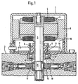
- Fig. 1 shows a basically known motor-pump unit on average. It consists of a motor housing 1 and a pump housing 2, which is attached to one another, for example are nested.
- the electric motor has via a motor shaft 3 which emerges from the motor housing 1 protrudes and engages in the pump housing 2.
- the electric motor also has basically known components such as armature 4, windings 5, collector 6 and brushes 7, whose Interaction with permanent magnets 8 is generally known is and needs no further explanation.
- the motor shaft 3 emerges from the motor housing 1 and engages in the pump housing 2.
- the pump side Housing cover 10 of the motor housing 1 is for this a gap 11 is provided so that the motor shaft is free can turn.
- a multi-stage bore 12 is provided in the pump housing 2 and a first hole stage is used to store the Motor shaft 3 with the help of a roller bearing 13. Then there is a crank chamber 14 in the pump housing 2, which an eccentric 15 arranged on the motor shaft 3 Creates space for its rotation. At the circumference of the eccentric 15 a needle bearing 16 is provided, which is vertical to the pump shaft 3 arranged pump pistons 17, 18 actuated.
- FIG. 2 9 proposed at least one sealing element 20 which the Gap 11 between engine interior 19 and crank chamber 14 blocked and arranged essentially on the housing cover 10 is.
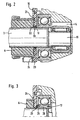
- a sealing element 20 is shown in FIG. 2.
- the housing cover extends 10 with its wall 21 almost up to the motor shaft 3 and has a bore 22 for shaft passage a small gap 11 to the motor shaft 3.
- the bore 22 is provided on its circumference with a circumferential groove 23, in a sealing element 20, preferably a sealing ring, is arranged is and the motor shaft 3 is acted upon radially.
- the Sealing element 20 is made of elastic material, for example made of silicone plastic, which is injected into the groove 23 is so that the gap 11 is reliably sealed when the sealing lip of the sealing element 20 rests on the motor shaft side.
- the housing cover 10 has on the collector side a recess 24 into which the collector 6 at least partially intervenes. Because the sealing element 20 with the housing cover 10 is aligned and narrower than the wall 21 and because at least one recess 24 is provided in the housing cover 10 in which the collector 6 engages at least partially, this arrangement has a particularly small one axial length. It goes without saying in this context it is also possible to provide a recess on the pump side, into which an assigned component, for example a Bearing ring engages. Thus, the smallest dimensions of the Aggregates a reliable seal of the motor housing 1 reached, even if the housing cover 10 on the motor side Brushes 7 holds, so especially close to the shaft bushing 9 are arranged.
- FIG. 3 shows the sealing and bearing area in detail the sealing element 20 in a cylindrical and annular Approach 25 arranged and acts on a bearing ring 26, for example, a bearing inner ring of the rolling bearing 13.
- the flange-like extension 25 jumps in on the pump side and axially Direction to the bearing ring 26 before.
- this one Design provided a recess 24 for the collector 6.
- a major advantage of this version is the possibility all components of the unit in the axial direction mount, the recess 24 to a shortened length leads.
- the housing cover 10 is included a stepped bore 27 on the pump side.
- a shaft seal ring 28 with an annular Stiffening and spring element 30 and with an elastic Sealing lip 31 used.
- the shaft seal is seated at a hole step.
- the elastic sealing lip 31 acts on the bearing inner ring of the rolling bearing 13.
- FIG. 5 the sealing element 20 in a stepped bore 27 on the pump side used.
- the sealing element 20 here comprises a stop ring 32, which is inserted into the stepped bore 27 and an O-ring 33, which is between the stop ring 32 and bearing ring 26 is squeezed and thus the gap 11th blocked between housing cover 10 and motor shaft 3.
- FIG. 6 A similar embodiment is shown in FIG. 6.
- the difference 5 is a through hole in the housing cover 10 before and the stop ring 32 is resilient and the resilient end 34 acts on a PTFE ring 35, which is pressed against the bearing ring 26.
- the PTFE ring 35 has particularly low coefficients of friction has, so that the loss due to friction minimal is. It is to minimize the friction work in all embodiments intended to act on the bearing inner ring, because it is the effective lever arm to the axis of the Motor shaft 3 becomes minimal.
- each of which has an end face 41 of the collector 6 is acted upon by the sealing element 20 becomes.
- the sealing element 20 has an annular Base body 42 and an angled, cone-like Section 43 on which the collector 6 in the axial direction applied.
- the housing cover 10 has a comparatively large gap 11 to the motor shaft 3.
- the gap between Housing cover 10 and motor shaft 3 minimized, that the housing cover 10 with its wall 21 particularly is brought close to the motor shaft 3.
- the sealing element 20 is located on an end face 44 of the engine Housing cover 10 inside a groove 45 and acted upon the associated counter surface 38 of the collector in the axial direction 6.
- the housing cover 10 has as in Fig. 7, both on the pump side and on the motor side recesses 24 ', 24, with the collector 6 engages at least partially in the motor-side recess 24.
Landscapes
- Engineering & Computer Science (AREA)
- Mechanical Engineering (AREA)
- Physics & Mathematics (AREA)
- General Engineering & Computer Science (AREA)
- Fluid Mechanics (AREA)
- Electromagnetism (AREA)
- Transportation (AREA)
- Power Engineering (AREA)
- Details And Applications Of Rotary Liquid Pumps (AREA)
- Connection Of Motors, Electrical Generators, Mechanical Devices, And The Like (AREA)
- Motor Or Generator Frames (AREA)
- Control Of Electric Motors In General (AREA)
- Control Of The Air-Fuel Ratio Of Carburetors (AREA)
Description
- Fig. 1
- Schnitt durch ein grundsätzlich bekanntes Elektromotor-/Pumpenaggregat;
- Fig. 2
- einen abgetrennten Schnitt durch ein Ausführungsbeispiel der Erfindung mit einem radial wirkenden Dichtelement in größerem Maßstab;
- Fig. 3
- abgetrennter Schnitt durch eine Einzelheit eines weiteren Ausführungsbeispieles mit axial wirkendem Dichtelement in größerem Maßstab;
- Fig. 4
- Schnitt wie in Fig. 3 durch eine weitere Ausführungsform;
- Fig. 5
- Schnitt wie in Fig. 3 durch ein viertes Ausführungsbeispiel;
- Fig. 6
- Schnitt wie in Fig. 3 durch ein fünftes Ausführungsbeispiel;
- Fig. 7
- Schnitt wie in Fig. 3 mit einem im Querschnitt als V-förmigen Dichtring ausgebildeten Dichtelement;
- Fig. 8
- Schnitt wie in Fig. 3 mit einem axial wirkenden, den Kommutator beaufschlagenden Dichtelement;
- Fig. 9
- Schnitt wie in Fig. 3 mit einer Abwandlung eines axial wirkenden, den Kommutator beaufschlagenden Dichtelementes.
Claims (16)
- Elektromotor-/Pumpenaggregat mit einem Elektromotor, dessen pumpenseitiges Ende einer Motorwelle (3) einen Gehäusedeckel (10) durchgreift, sich mit mindestens einem Wälzlager (13) an einem Pumpengehäuse (2) abstützt und zum Antrieb von Pumpenkolben (17,18) vorgesehen ist, wobei der Gehäusedeckel (10) im Bereich einer Wellendurchführung (9) einen Spalt (11) freiläßt, welcher einen pumpenseitigen Kurbelraum (14) mit einem Motorinnenraum (19) verbindet, dadurch gekennzeichnet, daß ein den Spalt (11) versperrendes Dichtelement (20) vorgesehen ist.
- Elektromotor-/Pumpenaggregat nach Anspruch 1, dadurch gekennzeichnet, daß das Dichtelement (20) am Gehäusedekkel (10) angeordnet ist und in radialer Richtung die Motorwelle (3) beaufschlagt.
- Elektromotor-/Pumpenaggregat nach einem oder mehreren der vorhergehenden Ansprüche, dadurch gekennzeichnet, daß der Gehäusedeckel (10) eine Bohrung (22) aufweist, welche wellenseitig mit einer Nut (23) für das Dichtelement (20) versehen ist.
- Elektromotor-/Pumpenaggregat nach einem oder mehreren der vorhergehenden Ansprüche, dadurch gekennzeichnet, daß der Gehäusedeckel (10) zur Bildung eines engen Spaltes (11) mit einer Wandung (21) nahe an die Motorwelle (3) heranreicht.
- Elektromotor-/Pumpenaggregat nach einem oder mehreren der vorhergehenden Ansprüche, dadurch gekennzeichnet, daß der Gehäusedeckel (10) kollektorseitig eine Ausnehmung (24) aufweist, in die der Kollektor (6) teilweise hineinreicht.
- Elektromotor-/Pumpenaggregat nach einem oder mehreren der vorhergehenden Ansprüche, dadurch gekennzeichnet, daß das Dichtelement (20) an einer Stirnseite des Gehäusedeckels (10) angeordnet ist und in axialer Richtung einen Lagerring (26) beaufschlagt.
- Elektromotor-/Pumpenaggregat nach einem oder mehreren der vorhergehenden Ansprüche, dadurch gekennzeichnet, daß der Gehäusedeckel (10) in axialer Richtung einen zylindrischen Ansatz (25) mit einer Nut (23) aufweist, in der das Dichtelement (20) angeordnet ist.
- Elektromotor-/Pumpenaggregat nach einem oder mehreren der vorhergehenden Ansprüche, dadurch gekennzeichnet, daß das Dichtelement (20) einen Lagerinnenring beaufschlagt.
- Elektromotor-/Pumpenaggregat nach einem oder mehreren der vorhergehenden Ansprüche, dadurch gekennzeichnet, daß das Dichtelement (20) als Wellendichtring (28) ausgebildet ist.
- Elektromotor-/Pumpenaggregat nach einem oder mehreren der vorhergehenden Ansprüche, dadurch gekennzeichnet, daß das Dichtelement (20) ein ringförmiges Versteifungs/und Federelement (30) sowie mindestens eine elastische Dichtlippe (31) aufweist.
- Elektromotor-/Pumpenaggregat nach einem oder mehreren der vorhergehenden Ansprüche, dadurch gekennzeichnet, daß das Dichtelement (20) in eine pumpenseitige Stufenbohrung (27) eingesetzt ist.
- Elektromotor-/Pumpenaggregat nach einem oder mehreren der vorhergehenden Ansprüche, dadurch gekennzeichnet, daß das Dichtelement (20) einen Anschlagring (32) und einen zugeordneten O-Ring (33) umfaßt, und zwischen Gehäusedeckel (10) und Lagerinnenring angeordnet ist.
- Elektromotor-/Pumpenaggregat nach einem oder mehreren der vorhergehenden Ansprüche, dadurch gekennzeichnet, daß der Anschlagring (32) federnd ausgebildet ist, wobei an einem federnden Ende (34) ein PTFE-Ring angeordnet ist.
- Elektromotor-/Pumpenaggregat nach einem oder mehreren der vorhergehenden Ansprüche, dadurch gekennzeichnet, daß das Dichtelement (20) Ringform sowie einen V-förmigen Querschnitt aufweist und in einem Zwischenraum (36) zwischen Lagerinnenring und Anschlagring (32) angeordnet ist.
- Elektromotor-/Pumpenaggregat nach einem oder mehreren der vorhergehenden Ansprüche, dadurch gekennzeichnet, daß das Dichtelement (20) an einer motorseitigen Stirnfläche (41) in einer Nut (45) des Gehäusedeckels (10) angeordnet ist und in axialer Richtung den Kollektor (6) beaufschlagt.
- Elektromotor-/Pumpenaggregat nach einem oder mehreren der vorhergehenden Ansprüche, dadurch gekennzeichnet, daß das Dichtelement (20) mit einem ringförmigen Grundkörper (42) in den Gehäusedeckel (10) eingesetzt ist und mit einem abgewinkelten, kegelartigen Abschnitt (43) in axialer Richtung den Kollektor (6) beaufschlagt.
Applications Claiming Priority (3)
| Application Number | Priority Date | Filing Date | Title |
|---|---|---|---|
| DE19633170A DE19633170A1 (de) | 1996-08-17 | 1996-08-17 | Eelektromotor-/Pumpenaggregat |
| DE19633170 | 1996-08-17 | ||
| PCT/EP1997/004044 WO1998007986A1 (de) | 1996-08-17 | 1997-07-25 | Elektromotor-/pumpenaggregat |
Publications (2)
| Publication Number | Publication Date |
|---|---|
| EP0918932A1 EP0918932A1 (de) | 1999-06-02 |
| EP0918932B1 true EP0918932B1 (de) | 2002-03-27 |
Family
ID=7802871
Family Applications (1)
| Application Number | Title | Priority Date | Filing Date |
|---|---|---|---|
| EP97936657A Expired - Lifetime EP0918932B1 (de) | 1996-08-17 | 1997-07-25 | Elektromotor-/pumpenaggregat |
Country Status (6)
| Country | Link |
|---|---|
| US (1) | US6200109B1 (de) |
| EP (1) | EP0918932B1 (de) |
| JP (1) | JP4159608B2 (de) |
| AT (1) | ATE215180T1 (de) |
| DE (2) | DE19633170A1 (de) |
| WO (1) | WO1998007986A1 (de) |
Cited By (1)
| Publication number | Priority date | Publication date | Assignee | Title |
|---|---|---|---|---|
| DE102006015897A1 (de) * | 2005-12-10 | 2007-06-14 | Continental Teves Ag & Co. Ohg | Elektromotor-Pumpenaggregat mit verbessertem Getriebe |
Families Citing this family (8)
| Publication number | Priority date | Publication date | Assignee | Title |
|---|---|---|---|---|
| DE19928480A1 (de) * | 1999-06-22 | 2000-12-28 | Bosch Gmbh Robert | Nadellager und Pumpeneinheit mit einem Nadellager |
| DE10131805A1 (de) * | 2000-07-29 | 2002-02-07 | Bosch Gmbh Robert | Pumpenaggregat für eine hydraulische Fahrzeugbremsanlage |
| EP1335478B1 (de) * | 2000-11-06 | 2007-07-25 | Matsushita Electric Industrial Co., Ltd. | Kleiner motor |
| US6848354B2 (en) | 2002-02-07 | 2005-02-01 | Gary L. Grochowski | Unitary rod/piston assembly |
| DE10252622A1 (de) * | 2002-11-11 | 2004-05-27 | Continental Teves Ag & Co. Ohg | Motor-Pumpen-Aggregat |
| DE20302174U1 (de) * | 2003-02-11 | 2004-09-09 | Minebea Co., Ltd. | Wellendichtung für einen Elektromotor und Elektromotor, insbesondere für ein automatisches Schaltgetriebe eines Kraftfahrzeuges |
| JP5001699B2 (ja) * | 2007-03-29 | 2012-08-15 | 日信工業株式会社 | 電動モータ |
| DE102018216558A1 (de) * | 2018-09-27 | 2020-04-02 | Robert Bosch Gmbh | Antriebseinrichtung, Hydraulikpumpe, Kraftfahrzeug |
Family Cites Families (32)
| Publication number | Priority date | Publication date | Assignee | Title |
|---|---|---|---|---|
| DE923589C (de) * | 1949-11-18 | 1955-02-17 | Heilmeier & Weinlein O H G | Hydraulik-Kolbenpumpe |
| GB1287011A (en) * | 1968-10-05 | 1972-08-31 | Duesterloh Gmbh | A hydraulic liquid distributor for a reversible hydraulic axial or radial piston machine |
| CH512671A (de) * | 1969-05-28 | 1971-09-15 | Bosch Gmbh Robert | Aus Pumpe und Elektromotor bestehende Hydraulikeinheit |
| US3658447A (en) * | 1970-04-09 | 1972-04-25 | Charles Bancroft | Pressure sealing assemblies for rotary vane piston devices |
| DE2362795C3 (de) * | 1973-12-18 | 1979-05-03 | Fa. Erwin Stelzer, 3530 Warburg | Elektrischer Ringmotor zum Antrieb eines für einen Behälter vorgesehenen Rührwerks |
| DE2413691B2 (de) * | 1974-03-21 | 1976-04-29 | Druckoelpumpe | |
| DE2433045C2 (de) * | 1974-07-10 | 1983-06-09 | Grundfos A/S, 8850 Bjerringbro | Dichtungsanordnung für die Welle eines zur Unterwassermontage eingerichteten Elektromotors |
| US4516921A (en) * | 1975-01-27 | 1985-05-14 | Vida M. Kemp | End seals for a rotary machine |
| DE2616437A1 (de) * | 1976-04-14 | 1977-10-27 | Fichtel & Sachs Ag | Radialkolbenpumpe |
| US4173437A (en) * | 1977-08-01 | 1979-11-06 | The Perkin-Elmer Corporation | Dual-piston reciprocating pump assembly |
| DE2936669C2 (de) * | 1979-09-11 | 1983-12-15 | Heilmeier & Weinlein Fabrik für Oel-Hydraulik GmbH & Co KG, 8000 München | Hydraulisches Pumpenaggregat. |
| US4336473A (en) * | 1979-11-05 | 1982-06-22 | Franklin Electric Co., Inc. | Electric motor |
| SE434084C (sv) * | 1981-04-15 | 1985-11-18 | Sven Schriwer | Forfarande och anordning for att teta ett vid hydrostatiska eller aerostatiska lager bildat fluidummottagningsanpassat lagringsutrymme |
| IT207371Z2 (it) * | 1986-03-25 | 1988-01-04 | Ansaldo Motori Spa | Gruppo di tenuta per macchine rotanti. |
| DE3780231T2 (de) | 1986-08-09 | 1993-03-04 | Nippon Denso Co | Motorangetriebene radialkolbenpumpe. |
| EP0276623A3 (de) * | 1987-01-28 | 1989-02-15 | Ice Cryogenic Engineering Ltd. | Rotationsverdichter |
| DE3722988A1 (de) | 1987-07-11 | 1989-01-19 | Teves Gmbh Alfred | Radialkolbenpumpe |
| IT217455Z2 (it) * | 1989-01-20 | 1991-12-13 | Interpump Spa | Motopompa composta da motore elettrico e da pompa per liquido a media e alta pressione, in particolare motopompa portatile a mano perlavaggio di cose |
| EP0405002B1 (de) * | 1989-06-30 | 1993-12-08 | Jakob, Karl, Dipl.-Ing.(FH) | Elektrischer Aussenläufermotor |
| JPH0741901Y2 (ja) * | 1990-06-12 | 1995-09-27 | 株式会社ナブコ | ポンプ装置 |
| US5167493A (en) * | 1990-11-22 | 1992-12-01 | Nissan Motor Co., Ltd. | Positive-displacement type pump system |
| DE4120665A1 (de) * | 1991-06-22 | 1992-12-24 | Teves Gmbh Alfred | Elektromotorisch angetriebene hydraulikpumpe |
| US5261676A (en) * | 1991-12-04 | 1993-11-16 | Environamics Corporation | Sealing arrangement with pressure responsive diaphragm means |
| DE4235962C2 (de) * | 1992-10-24 | 1997-11-27 | Temic Auto Electr Motors Gmbh | Elektromotor, insbesondere feuchtigkeitsdicht geschlossener Kommutatormotor mit einem axial angeflanschten Antriebsgehäuse |
| DE4423531A1 (de) | 1993-07-10 | 1995-01-12 | Licentia Gmbh | Elektromotor, insbesondere feuchtigkeitsdicht geschlossener Kommutatormotor mit einem an dem Motorgehäuse axial angeflanschten Antriebsgehäuse |
| US5484270A (en) * | 1994-02-28 | 1996-01-16 | Carmeli Adahan | Pump particularly useful in respirator apparatus and exhalation valve assembly therefor |
| EP0795085B1 (de) * | 1994-04-11 | 2000-09-13 | Enzo Mencarelli | Tauchpumpe mit doppelexzentem angetriebenem,koaxial gegenüberliegenden kolben |
| ES2082664T3 (es) | 1994-05-13 | 1996-03-16 | Siemens Ag | Equipo moto-bomba especialmente para un accionamiento abs. |
| DE4419927A1 (de) * | 1994-06-08 | 1995-12-14 | Bosch Gmbh Robert | Kolbenpumpe |
| DE4433970A1 (de) | 1994-09-23 | 1996-03-28 | Teves Gmbh Alfred | Elektromotor für ein Triebwerk, insbesondere für eine Pumpe |
| DE4445362A1 (de) * | 1994-12-20 | 1996-06-27 | Bosch Gmbh Robert | Kolbenpumpe |
| DE19754637A1 (de) * | 1996-12-17 | 1998-06-18 | Unipat Ag | Hydrostatische Radialkolbenpumpe |
-
1996
- 1996-08-17 DE DE19633170A patent/DE19633170A1/de not_active Withdrawn
-
1997
- 1997-07-25 EP EP97936657A patent/EP0918932B1/de not_active Expired - Lifetime
- 1997-07-25 JP JP51031898A patent/JP4159608B2/ja not_active Expired - Fee Related
- 1997-07-25 AT AT97936657T patent/ATE215180T1/de not_active IP Right Cessation
- 1997-07-25 WO PCT/EP1997/004044 patent/WO1998007986A1/de active IP Right Grant
- 1997-07-25 US US09/242,481 patent/US6200109B1/en not_active Expired - Fee Related
- 1997-07-25 DE DE59706785T patent/DE59706785D1/de not_active Expired - Lifetime
Cited By (1)
| Publication number | Priority date | Publication date | Assignee | Title |
|---|---|---|---|---|
| DE102006015897A1 (de) * | 2005-12-10 | 2007-06-14 | Continental Teves Ag & Co. Ohg | Elektromotor-Pumpenaggregat mit verbessertem Getriebe |
Also Published As
| Publication number | Publication date |
|---|---|
| DE19633170A1 (de) | 1998-02-19 |
| JP2000516680A (ja) | 2000-12-12 |
| DE59706785D1 (de) | 2002-05-02 |
| ATE215180T1 (de) | 2002-04-15 |
| WO1998007986A1 (de) | 1998-02-26 |
| US6200109B1 (en) | 2001-03-13 |
| EP0918932A1 (de) | 1999-06-02 |
| JP4159608B2 (ja) | 2008-10-01 |
Similar Documents
| Publication | Publication Date | Title |
|---|---|---|
| DE4315826C5 (de) | Motor-Pumpen-Aggregat | |
| DE19805003B4 (de) | Elektromotor | |
| DE3884845T2 (de) | Kreiselpumpe für elektrische Haushaltsgeräte, wie Waschmaschinen, Geschirrspülmaschinen und ähnliches. | |
| DE3327453C2 (de) | ||
| DE69515564T2 (de) | Seitenkanal-Pumpe mit geräuschdämpfender Vorrichtung | |
| DE10012181A1 (de) | Kreiselpumpe mit Noppen-Laufrad und Noppen-Laufrad hierfür | |
| EP0918932B1 (de) | Elektromotor-/pumpenaggregat | |
| DE102005032631B4 (de) | Fluiddynamisches Lagersystem | |
| DE2354039A1 (de) | Drehschieberpumpe | |
| DE69118133T2 (de) | Überflutbare Arbeitsmaschine | |
| DE102015106614A1 (de) | Pumpenvorrichtung | |
| DE102019118708A1 (de) | Druckversorgungseinrichtung mit einer Zahnradpumpe | |
| DE102006005604B4 (de) | Fluiddynamisches Lagersystem | |
| DE2735759C2 (de) | ||
| EP2600503B1 (de) | Bürstendeckel für einen bürstenkommutierten Elektromotor und Elektromotor | |
| DE2619094A1 (de) | Kraftstoffoerderaggregat | |
| EP2205868A1 (de) | Pumpe, insbesondere für ein hydraulikaggregat einer elektronisch regelbaren fahrzeugbremsanlage | |
| DE102015106611A1 (de) | Pumpenvorrichtung | |
| EP1336780B1 (de) | Sekundärdichtungselement für eine Gleitringdichtungsanordnung | |
| EP0415089A2 (de) | Axialdichtung | |
| DE102017206267A1 (de) | Pumpenaggregat, insbesondere zur Regelung eines Bremsdrucks in einer elektronisch schlupfregelbaren Fahrzeugbremsanlage | |
| EP0259714A1 (de) | Anlaufscheibe | |
| DE19528631A1 (de) | Zahnradmaschine | |
| DE3922434C2 (de) | ||
| DE4232939A1 (de) | Anlaufhilfe für drehrichtungsunabhängige Strömungspumpen mit einem Synchronmotor |
Legal Events
| Date | Code | Title | Description |
|---|---|---|---|
| PUAI | Public reference made under article 153(3) epc to a published international application that has entered the european phase |
Free format text: ORIGINAL CODE: 0009012 |
|
| 17P | Request for examination filed |
Effective date: 19990317 |
|
| AK | Designated contracting states |
Kind code of ref document: A1 Designated state(s): AT BE CH DE DK ES FI FR GB GR IE IT LI LU MC NL PT SE |
|
| RAP1 | Party data changed (applicant data changed or rights of an application transferred) |
Owner name: CONTINENTAL TEVES AG & CO. OHG |
|
| GRAG | Despatch of communication of intention to grant |
Free format text: ORIGINAL CODE: EPIDOS AGRA |
|
| 17Q | First examination report despatched |
Effective date: 20010605 |
|
| GRAG | Despatch of communication of intention to grant |
Free format text: ORIGINAL CODE: EPIDOS AGRA |
|
| GRAH | Despatch of communication of intention to grant a patent |
Free format text: ORIGINAL CODE: EPIDOS IGRA |
|
| REG | Reference to a national code |
Ref country code: GB Ref legal event code: IF02 |
|
| GRAH | Despatch of communication of intention to grant a patent |
Free format text: ORIGINAL CODE: EPIDOS IGRA |
|
| GRAA | (expected) grant |
Free format text: ORIGINAL CODE: 0009210 |
|
| AK | Designated contracting states |
Kind code of ref document: B1 Designated state(s): AT BE CH DE DK ES FI FR GB GR IE IT LI LU MC NL PT SE |
|
| PG25 | Lapsed in a contracting state [announced via postgrant information from national office to epo] |
Ref country code: NL Free format text: LAPSE BECAUSE OF FAILURE TO SUBMIT A TRANSLATION OF THE DESCRIPTION OR TO PAY THE FEE WITHIN THE PRESCRIBED TIME-LIMIT Effective date: 20020327 Ref country code: IE Free format text: LAPSE BECAUSE OF FAILURE TO SUBMIT A TRANSLATION OF THE DESCRIPTION OR TO PAY THE FEE WITHIN THE PRESCRIBED TIME-LIMIT Effective date: 20020327 Ref country code: GR Free format text: LAPSE BECAUSE OF FAILURE TO SUBMIT A TRANSLATION OF THE DESCRIPTION OR TO PAY THE FEE WITHIN THE PRESCRIBED TIME-LIMIT Effective date: 20020327 Ref country code: GB Free format text: LAPSE BECAUSE OF FAILURE TO SUBMIT A TRANSLATION OF THE DESCRIPTION OR TO PAY THE FEE WITHIN THE PRESCRIBED TIME-LIMIT Effective date: 20020327 Ref country code: FI Free format text: LAPSE BECAUSE OF FAILURE TO SUBMIT A TRANSLATION OF THE DESCRIPTION OR TO PAY THE FEE WITHIN THE PRESCRIBED TIME-LIMIT Effective date: 20020327 |
|
| REF | Corresponds to: |
Ref document number: 215180 Country of ref document: AT Date of ref document: 20020415 Kind code of ref document: T |
|
| REG | Reference to a national code |
Ref country code: CH Ref legal event code: EP |
|
| REF | Corresponds to: |
Ref document number: 59706785 Country of ref document: DE Date of ref document: 20020502 |
|
| REG | Reference to a national code |
Ref country code: IE Ref legal event code: FG4D Free format text: GERMAN |
|
| PG25 | Lapsed in a contracting state [announced via postgrant information from national office to epo] |
Ref country code: SE Free format text: LAPSE BECAUSE OF FAILURE TO SUBMIT A TRANSLATION OF THE DESCRIPTION OR TO PAY THE FEE WITHIN THE PRESCRIBED TIME-LIMIT Effective date: 20020627 Ref country code: PT Free format text: LAPSE BECAUSE OF FAILURE TO SUBMIT A TRANSLATION OF THE DESCRIPTION OR TO PAY THE FEE WITHIN THE PRESCRIBED TIME-LIMIT Effective date: 20020627 Ref country code: DK Free format text: LAPSE BECAUSE OF FAILURE TO SUBMIT A TRANSLATION OF THE DESCRIPTION OR TO PAY THE FEE WITHIN THE PRESCRIBED TIME-LIMIT Effective date: 20020627 |
|
| PG25 | Lapsed in a contracting state [announced via postgrant information from national office to epo] |
Ref country code: LU Free format text: LAPSE BECAUSE OF NON-PAYMENT OF DUE FEES Effective date: 20020725 Ref country code: AT Free format text: LAPSE BECAUSE OF NON-PAYMENT OF DUE FEES Effective date: 20020725 |
|
| PG25 | Lapsed in a contracting state [announced via postgrant information from national office to epo] |
Ref country code: LI Free format text: LAPSE BECAUSE OF NON-PAYMENT OF DUE FEES Effective date: 20020731 Ref country code: CH Free format text: LAPSE BECAUSE OF NON-PAYMENT OF DUE FEES Effective date: 20020731 Ref country code: BE Free format text: LAPSE BECAUSE OF NON-PAYMENT OF DUE FEES Effective date: 20020731 |
|
| ET | Fr: translation filed | ||
| NLV1 | Nl: lapsed or annulled due to failure to fulfill the requirements of art. 29p and 29m of the patents act | ||
| GBV | Gb: ep patent (uk) treated as always having been void in accordance with gb section 77(7)/1977 [no translation filed] |
Effective date: 20020327 |
|
| PG25 | Lapsed in a contracting state [announced via postgrant information from national office to epo] |
Ref country code: ES Free format text: LAPSE BECAUSE OF FAILURE TO SUBMIT A TRANSLATION OF THE DESCRIPTION OR TO PAY THE FEE WITHIN THE PRESCRIBED TIME-LIMIT Effective date: 20020925 |
|
| REG | Reference to a national code |
Ref country code: IE Ref legal event code: FD4D |
|
| BERE | Be: lapsed |
Owner name: *CONTINENTAL TEVES A.G. & CO. OHG Effective date: 20020731 |
|
| PLBE | No opposition filed within time limit |
Free format text: ORIGINAL CODE: 0009261 |
|
| STAA | Information on the status of an ep patent application or granted ep patent |
Free format text: STATUS: NO OPPOSITION FILED WITHIN TIME LIMIT |
|
| PG25 | Lapsed in a contracting state [announced via postgrant information from national office to epo] |
Ref country code: MC Free format text: LAPSE BECAUSE OF NON-PAYMENT OF DUE FEES Effective date: 20030201 |
|
| REG | Reference to a national code |
Ref country code: CH Ref legal event code: PL |
|
| 26N | No opposition filed |
Effective date: 20021230 |
|
| PGFP | Annual fee paid to national office [announced via postgrant information from national office to epo] |
Ref country code: FR Payment date: 20110729 Year of fee payment: 15 |
|
| PGFP | Annual fee paid to national office [announced via postgrant information from national office to epo] |
Ref country code: IT Payment date: 20110720 Year of fee payment: 15 |
|
| REG | Reference to a national code |
Ref country code: FR Ref legal event code: ST Effective date: 20130329 |
|
| PG25 | Lapsed in a contracting state [announced via postgrant information from national office to epo] |
Ref country code: FR Free format text: LAPSE BECAUSE OF NON-PAYMENT OF DUE FEES Effective date: 20120731 |
|
| PG25 | Lapsed in a contracting state [announced via postgrant information from national office to epo] |
Ref country code: IT Free format text: LAPSE BECAUSE OF NON-PAYMENT OF DUE FEES Effective date: 20120725 |
|
| PGFP | Annual fee paid to national office [announced via postgrant information from national office to epo] |
Ref country code: DE Payment date: 20130731 Year of fee payment: 17 |
|
| REG | Reference to a national code |
Ref country code: DE Ref legal event code: R119 Ref document number: 59706785 Country of ref document: DE |
|
| PG25 | Lapsed in a contracting state [announced via postgrant information from national office to epo] |
Ref country code: DE Free format text: LAPSE BECAUSE OF NON-PAYMENT OF DUE FEES Effective date: 20150203 |
|
| REG | Reference to a national code |
Ref country code: DE Ref legal event code: R119 Ref document number: 59706785 Country of ref document: DE Effective date: 20150203 |