EP0916524A2 - Radiale Luftreifen - Google Patents
Radiale Luftreifen Download PDFInfo
- Publication number
- EP0916524A2 EP0916524A2 EP98308987A EP98308987A EP0916524A2 EP 0916524 A2 EP0916524 A2 EP 0916524A2 EP 98308987 A EP98308987 A EP 98308987A EP 98308987 A EP98308987 A EP 98308987A EP 0916524 A2 EP0916524 A2 EP 0916524A2
- Authority
- EP
- European Patent Office
- Prior art keywords
- tire
- block
- blocks
- tread
- pneumatic radial
- Prior art date
- Legal status (The legal status is an assumption and is not a legal conclusion. Google has not performed a legal analysis and makes no representation as to the accuracy of the status listed.)
- Withdrawn
Links
Images
Classifications
-
- B—PERFORMING OPERATIONS; TRANSPORTING
- B60—VEHICLES IN GENERAL
- B60C—VEHICLE TYRES; TYRE INFLATION; TYRE CHANGING; CONNECTING VALVES TO INFLATABLE ELASTIC BODIES IN GENERAL; DEVICES OR ARRANGEMENTS RELATED TO TYRES
- B60C11/00—Tyre tread bands; Tread patterns; Anti-skid inserts
- B60C11/03—Tread patterns
- B60C11/13—Tread patterns characterised by the groove cross-section, e.g. for buttressing or preventing stone-trapping
- B60C11/1376—Three dimensional block surfaces departing from the enveloping tread contour
- B60C11/1384—Three dimensional block surfaces departing from the enveloping tread contour with chamfered block corners
-
- B—PERFORMING OPERATIONS; TRANSPORTING
- B60—VEHICLES IN GENERAL
- B60C—VEHICLE TYRES; TYRE INFLATION; TYRE CHANGING; CONNECTING VALVES TO INFLATABLE ELASTIC BODIES IN GENERAL; DEVICES OR ARRANGEMENTS RELATED TO TYRES
- B60C11/00—Tyre tread bands; Tread patterns; Anti-skid inserts
- B60C11/03—Tread patterns
- B60C11/0302—Tread patterns directional pattern, i.e. with main rolling direction
-
- B—PERFORMING OPERATIONS; TRANSPORTING
- B60—VEHICLES IN GENERAL
- B60C—VEHICLE TYRES; TYRE INFLATION; TYRE CHANGING; CONNECTING VALVES TO INFLATABLE ELASTIC BODIES IN GENERAL; DEVICES OR ARRANGEMENTS RELATED TO TYRES
- B60C11/00—Tyre tread bands; Tread patterns; Anti-skid inserts
- B60C11/03—Tread patterns
- B60C11/13—Tread patterns characterised by the groove cross-section, e.g. for buttressing or preventing stone-trapping
-
- B—PERFORMING OPERATIONS; TRANSPORTING
- B60—VEHICLES IN GENERAL
- B60C—VEHICLE TYRES; TYRE INFLATION; TYRE CHANGING; CONNECTING VALVES TO INFLATABLE ELASTIC BODIES IN GENERAL; DEVICES OR ARRANGEMENTS RELATED TO TYRES
- B60C11/00—Tyre tread bands; Tread patterns; Anti-skid inserts
- B60C11/03—Tread patterns
- B60C2011/0337—Tread patterns characterised by particular design features of the pattern
- B60C2011/0339—Grooves
- B60C2011/0374—Slant grooves, i.e. having an angle of about 5 to 35 degrees to the equatorial plane
-
- B—PERFORMING OPERATIONS; TRANSPORTING
- B60—VEHICLES IN GENERAL
- B60C—VEHICLE TYRES; TYRE INFLATION; TYRE CHANGING; CONNECTING VALVES TO INFLATABLE ELASTIC BODIES IN GENERAL; DEVICES OR ARRANGEMENTS RELATED TO TYRES
- B60C11/00—Tyre tread bands; Tread patterns; Anti-skid inserts
- B60C11/03—Tread patterns
- B60C2011/0337—Tread patterns characterised by particular design features of the pattern
- B60C2011/0386—Continuous ribs
- B60C2011/0388—Continuous ribs provided at the equatorial plane
Definitions
- This invention relates to a pneumatic tire and more particularly to a pneumatic radial tire comprising a tread provided with many blocks defined by grooves and/or sipes.
- an object of the invention to solve the aforementioned problems in the pneumatic tire comprising a tread provided with many blocks defined by grooves and/or sipes and to provide a pneumatic radial tire for passenger car having excellent level of pattern noise and steering stability by making the ground contact pressure of the block as uniform as possible.
- a pneumatic radial tire comprising a tread provided with many blocks defined by grooves and/or sipes, in which (1) a peripheral portion of each of the blocks is chamfered in form of a curve or a straight line over a region corresponding to 20-80% of a shortest distance from a center of gravity of each block to a side of each block at a chamfering depth of 0.1-0.5 mm in a mold during the vulcanization of the tire, and (2) the outer surface of the block becomes flat or substantially flat when the tire after the vulcanization is assembled onto a normal rim and inflated under a normal internal pressure.
- the pneumatic tire is used by assembling onto a standard rim standardized through JATMA (Japan), TRA (USA), ETRTO (Europe) or the like in accordance with the size of the tire.
- This standard rim is usually called as a normal rim.
- the term "normal rim” used herein means a standard rim corresponding to an applied size and ply rating defined in JATMA YEAR BOOK 1997.
- normal load and "normal internal pressure” used herein mean a maximum load capacity corresponding to an applied size and ply rating and an air pressure corresponding to the maximum load capacity defined in JATMA YEAR BOOK 1997, respectively.
- the "normal internal pressure” in this specification indicates 180 kPa according to a “measurement method for tires” defined in JATMA YEAR BOOK 1997, and the "normal load” indicates 88% of the maximum load capacity corresponding to the applied size and ply rating.
- the pneumatic radial tire according to the invention has the above structure that the peripheral portion of each of the blocks facing the groove and/or the sipe is chamfered in form of a curve or a straight line over the region corresponding to 20-80% of the shortest distance from the center of gravity of each block to a side of each block at the chamfering depth of 0.1-0.5 mm in the mold during the vulcanization of the tire, whereby the outer surface of the block is made flat or substantially flat when the tire after the vulcanization is taken out from the mold and assembled onto the normal rim and inflated under the normal internal pressure. Therefore, the problem of the conventional technique that the ground contact pressure of the block becomes ununiform is solved and hence there is provided the pneumatic radial tire having excellent pattern noise level and steering stability.
- the chamfering depth is less than 0.1 mm, the ground contact pressure at each side of the block is not sufficiently decreased, while when it exceeds 0.5 mm, the outer surface of the block becomes not flat when the tire is assembled onto the rim and inflated under the internal pressure and hence when the block contacts with ground, the ground contact pressure of the side of the block is too low or the side of the block does not contact with ground.
- the chamfering depth is outside the range defined in the invention, the distribution of the ground contact pressure becomes ununiform.
- the chamfering depth is 0.2-0.4 mm.
- the chamfering width in each side of the block is less than 20% of the shortest distance, the ground contact pressure at the side of the block is not sufficiently decreased, while when it exceeds 80% of the shortest distance, the ground contact pressure at the central portion of the block becomes too high.
- the chamfering width is outside the range defined in the invention, the distribution of the ground contact pressure becomes ununiform.
- the chamfering width is 20-50%.
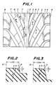
- Fig. 1 is shown a partly enlarged schematic view of an embodiment of the tread pattern in the pneumatic radial tire for passenger car according to the invention.
- the tire size is 235/45ZR17.
- a tread of the tire comprises a central rib 1 extending in a circumferential direction of the tire, plural slant main grooves 2 arranged on both sides of the central rib 1 and extending in a direction inclined with respect to the circumferential direction in herringbone form, plural central circumferential grooves 3 each arranged in a central region of the tread and connecting adjacent slant main grooves 2 to each other, plural side circumferential grooves 4 each arranged in each of side regions of the tread and connecting adjacent slant main grooves 2 to each other, plural side slant grooves 5 each extending from the side circumferential groove 4 toward an end of the tread, plural sipes 6 arranged in a land portion defined by the grooves 2, 3 and 4 and many blocks 7 defined by the grooves 2 to 5 and sipes 6.
- the main slant grooves 2 extend in a direction inclined at an angle of 15-45° with respect to the circumferential direction and are arranged at given intervals in the circumferential direction. And also, these main slant grooves form a directional tread pattern designating a rotating direction of the tire so as to contact a portion of the main slant groove 2 located far away from an end of the tread earlier than a portion near to the end of the tread with ground in the mounting onto a vehicle.
- the main slant grooves 2 extend in a direction inclined at an angle of 15-45° with respect to the circumferential direction and are arranged at given intervals in the circumferential direction, but may form a non-directional tread pattern wherein a portion of the main slant groove 2 located far away from an end of the tread contacts with ground earlier than a portion near to the end of the tread in a half region of the tread and the ground contacting relation becomes reverse in the remaining half region of the tread.
- each of the blocks 7 is curvedly chamfered in a mold during the vulcanization.
- the width to be chamfered in the block is 20-80% of a shortest distance L from a center of gravity G of each block to a side P of the each block to be chamfered.
- side P used herein is defined by an intersecting point between an extension line of a mold face forming an outer surface of the block and an extension line of a mold face forming a sidewall of the block.
- the chamfering width a in the longitudinal direction of the block is 5 mm, which corresponds to 22% of a shortest distance L(1) from the center of gravity G of the block to the side P thereof.
- the chamfering width b in the transverse direction of the block is 4 mm, which corresponds to 46% of a shortest distance L(m) from the center of gravity G of the block to the side P thereof.
- the chamfering depths c, d of the blocks shown in Figs. 2 and 3 are 0.3 mm, respectively.
- each of the blocks 7 other than blocks 8 facing the tread end is chamfered at four sides or over a full periphery.
- each of the blocks 8 is chamfered only at sides facing the main slant groove 2, side circumferential groove 4 and side slant groove 5. In other words, a side of the block 8 constituting the tread end is not chamfered.
- the peripheral portion of the each of the block is curvedly chamfered in the mold during the vulcanization as mentioned above, so that when the tire after the vulcanization is assembled onto a normal rim and inflated under a normal internal pressure, the outer surface of each of the blocks becomes substantially flat.
- the tire of the illustrated embodiment has a tire size of 235/45ZR17, the normal rim or standard rim is 8JJ-17, and the normal internal pressure is 180 kPa (1.8 kgf/cm 2 ), and the normal load is 88% of the maximum load capacity (650 kg) and is 570 kg.
- the pneumatic tire has the same structure as in the embodiment of the invention except that the peripheral portion of each of the blocks is not chamfered in the mold during the vulcanization.
- the pattern noise is evaluated by measuring a tire noise through a microphone located at a position corresponding to an ear of a test driver when the tire is run on a smooth straight road at a speed of 60 km/h.
- the index value of the noise level of the tire in the embodiment according to the invention is 105.
- the steering stability is evaluated by a test driver's feeling when the tire is run on a dry circuit test course having a radius of 50 m under various running modes.
- the index value of the steering stability of the tire in the embodiment according to the invention is 107.
- the pneumatic radial tire according to the invention is superior in the noise level and the steering stability to the conventional pneumatic radial tire.
Landscapes
- Engineering & Computer Science (AREA)
- Mechanical Engineering (AREA)
- Tires In General (AREA)
Applications Claiming Priority (3)
| Application Number | Priority Date | Filing Date | Title |
|---|---|---|---|
| JP31012997 | 1997-11-12 | ||
| JP310129/97 | 1997-11-12 | ||
| JP31012997 | 1997-11-12 |
Publications (2)
| Publication Number | Publication Date |
|---|---|
| EP0916524A2 true EP0916524A2 (de) | 1999-05-19 |
| EP0916524A3 EP0916524A3 (de) | 2000-11-08 |
Family
ID=18001528
Family Applications (1)
| Application Number | Title | Priority Date | Filing Date |
|---|---|---|---|
| EP98308987A Withdrawn EP0916524A3 (de) | 1997-11-12 | 1998-11-03 | Radiale Luftreifen |
Country Status (2)
| Country | Link |
|---|---|
| US (1) | US6098681A (de) |
| EP (1) | EP0916524A3 (de) |
Cited By (2)
| Publication number | Priority date | Publication date | Assignee | Title |
|---|---|---|---|---|
| WO2010023076A1 (fr) * | 2008-08-26 | 2010-03-04 | Societe De Technologie Michelin | Bande de roulement de pneu a sculpture directionnelle |
| CN101607512B (zh) * | 2008-06-18 | 2012-09-05 | 青岛黄海橡胶股份有限公司 | 轿车子午线轮胎胎面 |
Families Citing this family (4)
| Publication number | Priority date | Publication date | Assignee | Title |
|---|---|---|---|---|
| US6983777B2 (en) * | 2002-10-15 | 2006-01-10 | The Goodyear Tire & Rubber Company | Tire tread with multi-planar chamfers |
| USD535610S1 (en) * | 2005-04-25 | 2007-01-23 | The Yokohama Rubber Co., Ltd. | Automobile tire |
| JPWO2012141149A1 (ja) * | 2011-04-15 | 2014-07-28 | 株式会社ブリヂストン | 自動二輪車用空気入りタイヤ |
| JP7639368B2 (ja) * | 2021-01-28 | 2025-03-05 | 住友ゴム工業株式会社 | タイヤ |
Family Cites Families (14)
| Publication number | Priority date | Publication date | Assignee | Title |
|---|---|---|---|---|
| GB1501434A (en) * | 1974-07-22 | 1978-02-15 | Goodyear Tire & Rubber | Pneumatic tyre and method of making same |
| JPS52140102A (en) * | 1976-05-19 | 1977-11-22 | Bridgestone Corp | Pneumatic tyre with less partial wear |
| US4722378A (en) * | 1986-05-19 | 1988-02-02 | The Goodyear Tire & Rubber Company | Tire treads with convex elements |
| JPS63162307A (ja) * | 1986-12-26 | 1988-07-05 | Bridgestone Corp | 高速走行に供される空気入りラジアルタイヤ |
| EP0305617B1 (de) * | 1987-09-04 | 1992-11-11 | Sumitomo Rubber Industries Limited | Valukanisierungsform für Luftreifen |
| JP3193452B2 (ja) * | 1992-05-25 | 2001-07-30 | 株式会社ブリヂストン | 空気入りタイヤ |
| JP3380605B2 (ja) * | 1993-05-20 | 2003-02-24 | 株式会社ブリヂストン | 空気入りタイヤ |
| EP0688685B1 (de) * | 1994-06-23 | 2000-08-23 | Bridgestone Corporation | Luftreifen |
| JP3467081B2 (ja) * | 1994-08-08 | 2003-11-17 | 株式会社ブリヂストン | 空気入りラジアルタイヤ |
| JP3388902B2 (ja) * | 1994-09-20 | 2003-03-24 | 株式会社ブリヂストン | 空気入りラジアルタイヤ |
| JPH08104109A (ja) * | 1994-10-06 | 1996-04-23 | Bridgestone Corp | 空気入りタイヤ |
| JP3555777B2 (ja) * | 1994-11-22 | 2004-08-18 | 株式会社ブリヂストン | 方向性傾斜溝を有する高運動性能空気入りタイヤ |
| JPH08310205A (ja) * | 1995-05-22 | 1996-11-26 | Bridgestone Corp | V字型方向性低傾斜溝を有する空気入りタイヤ |
| JP3542687B2 (ja) * | 1996-06-11 | 2004-07-14 | 株式会社ブリヂストン | 空気入りタイヤ |
-
1998
- 1998-11-03 EP EP98308987A patent/EP0916524A3/de not_active Withdrawn
- 1998-11-12 US US09/189,980 patent/US6098681A/en not_active Expired - Lifetime
Cited By (4)
| Publication number | Priority date | Publication date | Assignee | Title |
|---|---|---|---|---|
| CN101607512B (zh) * | 2008-06-18 | 2012-09-05 | 青岛黄海橡胶股份有限公司 | 轿车子午线轮胎胎面 |
| WO2010023076A1 (fr) * | 2008-08-26 | 2010-03-04 | Societe De Technologie Michelin | Bande de roulement de pneu a sculpture directionnelle |
| EA018005B1 (ru) * | 2008-08-26 | 2013-04-30 | Компани Женераль Дез Этаблиссман Мишлен | Протектор шины с направленным рисунком |
| US8783313B2 (en) | 2008-08-26 | 2014-07-22 | Compagnie Generale Des Etablissements | Tire tread with directional pattern |
Also Published As
| Publication number | Publication date |
|---|---|
| EP0916524A3 (de) | 2000-11-08 |
| US6098681A (en) | 2000-08-08 |
Similar Documents
| Publication | Publication Date | Title |
|---|---|---|
| EP2163405B1 (de) | Luftreifen | |
| US6340040B1 (en) | Vehicle tire including main grooves and lug grooves | |
| US8210219B2 (en) | Pneumatic tire with tread having crown rib and middle ribs | |
| EP2151333B1 (de) | Luftreifen | |
| EP2239153B1 (de) | Luftreifen | |
| EP3095623B1 (de) | Luftreifen | |
| EP0904960B1 (de) | Spikeloser luftreifen | |
| JP3822338B2 (ja) | 空気入りタイヤ | |
| EP0713789B1 (de) | PKW-Luftreifen | |
| EP1437237A2 (de) | Luftreifen | |
| JP4274317B2 (ja) | 空気入りタイヤ | |
| CN103381740B (zh) | 充气轮胎 | |
| CA2528632C (en) | Pneumatic tire | |
| EP3501852B1 (de) | Reifen | |
| KR20100005659A (ko) | 공기입 타이어, 타이어 몰드, 및 공기입 타이어의 제조 방법 | |
| JPH07186623A (ja) | 空気入りタイヤ | |
| EP0870630A2 (de) | Luftreifen | |
| CA2167192A1 (en) | Pneumatic radial tire | |
| CN111070974A (zh) | 充气轮胎 | |
| WO2021054261A1 (ja) | タイヤ | |
| CN111433051B (zh) | 充气轮胎 | |
| CN111572080A (zh) | 充气轮胎、轮胎硫化模具以及使用了轮胎硫化模具的充气轮胎的制造方法 | |
| US20220097456A1 (en) | Tire | |
| US11654721B2 (en) | Tire | |
| JPH0939515A (ja) | 乗用車用空気入りタイヤ |
Legal Events
| Date | Code | Title | Description |
|---|---|---|---|
| PUAI | Public reference made under article 153(3) epc to a published international application that has entered the european phase |
Free format text: ORIGINAL CODE: 0009012 |
|
| AK | Designated contracting states |
Kind code of ref document: A2 Designated state(s): DE ES FR GB IT |
|
| AX | Request for extension of the european patent |
Free format text: AL;LT;LV;MK;RO;SI |
|
| PUAL | Search report despatched |
Free format text: ORIGINAL CODE: 0009013 |
|
| AK | Designated contracting states |
Kind code of ref document: A3 Designated state(s): AT BE CH CY DE DK ES FI FR GB GR IE IT LI LU MC NL PT SE |
|
| AX | Request for extension of the european patent |
Free format text: AL;LT;LV;MK;RO;SI |
|
| RIC1 | Information provided on ipc code assigned before grant |
Free format text: 7B 60C 11/13 A, 7B 60C 11/00 B, 7B 60C 11/03 B, 7B 60C 11/11 B, 7B 60C 115:00 Z |
|
| 17P | Request for examination filed |
Effective date: 20010306 |
|
| AKX | Designation fees paid |
Free format text: DE ES FR GB IT |
|
| 17Q | First examination report despatched |
Effective date: 20021004 |
|
| STAA | Information on the status of an ep patent application or granted ep patent |
Free format text: STATUS: THE APPLICATION IS DEEMED TO BE WITHDRAWN |
|
| 18D | Application deemed to be withdrawn |
Effective date: 20030415 |