EP0914203B1 - A method and a reactor for electrochemical conversion of a material e.g. soot particles being insoluble in a fluid - Google Patents
A method and a reactor for electrochemical conversion of a material e.g. soot particles being insoluble in a fluid Download PDFInfo
- Publication number
- EP0914203B1 EP0914203B1 EP97923836A EP97923836A EP0914203B1 EP 0914203 B1 EP0914203 B1 EP 0914203B1 EP 97923836 A EP97923836 A EP 97923836A EP 97923836 A EP97923836 A EP 97923836A EP 0914203 B1 EP0914203 B1 EP 0914203B1
- Authority
- EP
- European Patent Office
- Prior art keywords
- electrode
- fluid
- ion
- electrochemical
- electrolyte
- Prior art date
- Legal status (The legal status is an assumption and is not a legal conclusion. Google has not performed a legal analysis and makes no representation as to the accuracy of the status listed.)
- Expired - Lifetime
Links
Images


Classifications
-
- F—MECHANICAL ENGINEERING; LIGHTING; HEATING; WEAPONS; BLASTING
- F01—MACHINES OR ENGINES IN GENERAL; ENGINE PLANTS IN GENERAL; STEAM ENGINES
- F01N—GAS-FLOW SILENCERS OR EXHAUST APPARATUS FOR MACHINES OR ENGINES IN GENERAL; GAS-FLOW SILENCERS OR EXHAUST APPARATUS FOR INTERNAL COMBUSTION ENGINES
- F01N3/00—Exhaust or silencing apparatus having means for purifying, rendering innocuous, or otherwise treating exhaust
- F01N3/08—Exhaust or silencing apparatus having means for purifying, rendering innocuous, or otherwise treating exhaust for rendering innocuous
- F01N3/0892—Electric or magnetic treatment, e.g. dissociation of noxious components
-
- B—PERFORMING OPERATIONS; TRANSPORTING
- B01—PHYSICAL OR CHEMICAL PROCESSES OR APPARATUS IN GENERAL
- B01D—SEPARATION
- B01D17/00—Separation of liquids, not provided for elsewhere, e.g. by thermal diffusion
- B01D17/02—Separation of non-miscible liquids
- B01D17/04—Breaking emulsions
- B01D17/042—Breaking emulsions by changing the temperature
-
- B—PERFORMING OPERATIONS; TRANSPORTING
- B01—PHYSICAL OR CHEMICAL PROCESSES OR APPARATUS IN GENERAL
- B01D—SEPARATION
- B01D17/00—Separation of liquids, not provided for elsewhere, e.g. by thermal diffusion
- B01D17/02—Separation of non-miscible liquids
- B01D17/04—Breaking emulsions
- B01D17/048—Breaking emulsions by changing the state of aggregation
-
- B—PERFORMING OPERATIONS; TRANSPORTING
- B01—PHYSICAL OR CHEMICAL PROCESSES OR APPARATUS IN GENERAL
- B01D—SEPARATION
- B01D17/00—Separation of liquids, not provided for elsewhere, e.g. by thermal diffusion
- B01D17/06—Separation of liquids from each other by electricity
-
- F—MECHANICAL ENGINEERING; LIGHTING; HEATING; WEAPONS; BLASTING
- F01—MACHINES OR ENGINES IN GENERAL; ENGINE PLANTS IN GENERAL; STEAM ENGINES
- F01N—GAS-FLOW SILENCERS OR EXHAUST APPARATUS FOR MACHINES OR ENGINES IN GENERAL; GAS-FLOW SILENCERS OR EXHAUST APPARATUS FOR INTERNAL COMBUSTION ENGINES
- F01N3/00—Exhaust or silencing apparatus having means for purifying, rendering innocuous, or otherwise treating exhaust
- F01N3/01—Exhaust or silencing apparatus having means for purifying, rendering innocuous, or otherwise treating exhaust by means of electric or electrostatic separators
-
- C—CHEMISTRY; METALLURGY
- C02—TREATMENT OF WATER, WASTE WATER, SEWAGE, OR SLUDGE
- C02F—TREATMENT OF WATER, WASTE WATER, SEWAGE, OR SLUDGE
- C02F1/00—Treatment of water, waste water, or sewage
- C02F1/46—Treatment of water, waste water, or sewage by electrochemical methods
- C02F1/461—Treatment of water, waste water, or sewage by electrochemical methods by electrolysis
- C02F1/46104—Devices therefor; Their operating or servicing
-
- C—CHEMISTRY; METALLURGY
- C02—TREATMENT OF WATER, WASTE WATER, SEWAGE, OR SLUDGE
- C02F—TREATMENT OF WATER, WASTE WATER, SEWAGE, OR SLUDGE
- C02F1/00—Treatment of water, waste water, or sewage
- C02F1/46—Treatment of water, waste water, or sewage by electrochemical methods
- C02F1/461—Treatment of water, waste water, or sewage by electrochemical methods by electrolysis
- C02F1/467—Treatment of water, waste water, or sewage by electrochemical methods by electrolysis by electrochemical disinfection; by electrooxydation or by electroreduction
- C02F1/4672—Treatment of water, waste water, or sewage by electrochemical methods by electrolysis by electrochemical disinfection; by electrooxydation or by electroreduction by electrooxydation
-
- C—CHEMISTRY; METALLURGY
- C02—TREATMENT OF WATER, WASTE WATER, SEWAGE, OR SLUDGE
- C02F—TREATMENT OF WATER, WASTE WATER, SEWAGE, OR SLUDGE
- C02F1/00—Treatment of water, waste water, or sewage
- C02F1/46—Treatment of water, waste water, or sewage by electrochemical methods
- C02F1/461—Treatment of water, waste water, or sewage by electrochemical methods by electrolysis
- C02F1/46104—Devices therefor; Their operating or servicing
- C02F1/46109—Electrodes
- C02F2001/46133—Electrodes characterised by the material
-
- C—CHEMISTRY; METALLURGY
- C02—TREATMENT OF WATER, WASTE WATER, SEWAGE, OR SLUDGE
- C02F—TREATMENT OF WATER, WASTE WATER, SEWAGE, OR SLUDGE
- C02F1/00—Treatment of water, waste water, or sewage
- C02F1/46—Treatment of water, waste water, or sewage by electrochemical methods
- C02F1/461—Treatment of water, waste water, or sewage by electrochemical methods by electrolysis
- C02F1/46104—Devices therefor; Their operating or servicing
- C02F1/46109—Electrodes
- C02F2001/46152—Electrodes characterised by the shape or form
-
- C—CHEMISTRY; METALLURGY
- C02—TREATMENT OF WATER, WASTE WATER, SEWAGE, OR SLUDGE
- C02F—TREATMENT OF WATER, WASTE WATER, SEWAGE, OR SLUDGE
- C02F2101/00—Nature of the contaminant
- C02F2101/30—Organic compounds
- C02F2101/32—Hydrocarbons, e.g. oil
-
- Y—GENERAL TAGGING OF NEW TECHNOLOGICAL DEVELOPMENTS; GENERAL TAGGING OF CROSS-SECTIONAL TECHNOLOGIES SPANNING OVER SEVERAL SECTIONS OF THE IPC; TECHNICAL SUBJECTS COVERED BY FORMER USPC CROSS-REFERENCE ART COLLECTIONS [XRACs] AND DIGESTS
- Y02—TECHNOLOGIES OR APPLICATIONS FOR MITIGATION OR ADAPTATION AGAINST CLIMATE CHANGE
- Y02T—CLIMATE CHANGE MITIGATION TECHNOLOGIES RELATED TO TRANSPORTATION
- Y02T10/00—Road transport of goods or passengers
- Y02T10/10—Internal combustion engine [ICE] based vehicles
- Y02T10/12—Improving ICE efficiencies
Definitions
- the present invention relates to a method for electrochemical conversion of a material being insoluble in a fluid into a material being soluble in the fluid; an electrochemical reactor; an ion-selective electrolyte, an electrode, and a mixed ion-selective electrolyte, and electrode material for use when carrying out the method and for use in the electrochemical reactor, and use of the method and for use of the reactor for removal of soot particles from flue gases and oil in waste water.
- Partially combusted material and soot particles are consequently accumulated in the filter, for which reason it must periodically be regenerated in order to remove or combust the soot particles collected.
- the regeneration must typically be performed at intervals of a few hours, i.e. several times during a service day for e.g. a bus.
- the regeneration is typically initiated by heating the filter with a burner or an electrical heating element.
- the exhaust gas flow must be bypassed the filter unit, whereby the exhaust gas is not filtered.
- the engine may be stopped during the regeneration period.
- a regeneration typically takes from a few minutes up to 20 minutes. As the filter is loaded during the service period, the counter pressure increases because of the clogging.
- EP 532 031 discloses a burner system based on diesel fuel for regeneration of filters for the collection of particulate material from the exhaust gases from diesel engines. The collected material is ignited by heating with a burner. The system has the drawback that it cannot be operated on a continuous basis.
- WO 95/02 117 discloses a filter for collection of particulate materials from the exhaust from a diesel engine. This filter is regenerated by heating the filter body electrically to the ignition temperature of the soot collected. Alternatively, a diesel fuelled burner can be used to initiate the ignition of the particulate material. This system is not a continuously functioning system, since periodically it must be taken out of service for regeneration.
- WO 94/16 204 discloses a filter system, primarily for use on the exhaust from forklifts and other diesel fuelled vehicles which are not intended for street use.
- the regeneration of the filter is accomplished in a set-up where air for the combustion and electrical power for heating the collected material to its ignition temperature are supplied from an external source. Thus, the vehicle must be out of service, while the regeneration takes place.
- US patent No. 4 946 609 discloses a system where the temperature for the catalytic combustion is lowered by means of addition of an additive to the fuel or the lubricating oil.
- the filter should be self-cleaning at about 300 °C.
- the system is, however, complicated by the fact that a dosing mechanism for the additive must be introduced. Besides, there is potentially increased risk of clogging of the filter due to residues of the additive, and there is risk of environmental external contamination due to release of additive.
- US patent No. 4 902 487 discloses a filter system, in which a relatively high content of nitrogen oxides is required in the exhaust gas. These oxides serve as an active oxidizing agent, whereby the minimum temperature for the catalytic combustion of soot particles can be lowered. However, in order to obtain self-cleaning of the filter at temperatures over 275 °C, a suitably high proportion of content of nitrogen oxides to the amount of soot is necessary. Thus, the system only functions in systems with low soot content in the exhaust gas and being well maintained. Furthermore, the exhaust gas is discharged with an undesirably high content of nitrogen oxides.
- US patent application No. 4 310 406 describes a system in which a granulate of carbon or the like is used as electrode in electrochemical purification of waste water, wherein an electrochemical reaction is utilized to convert a pollutant in solution, essentially metal ions, into an insoluble, particulate material which is collected on the electrode material.
- an electrochemical reaction is utilized to convert a pollutant in solution, essentially metal ions, into an insoluble, particulate material which is collected on the electrode material.
- the opposite process, in which an insoluble material is converted into a soluble material is neither shown nor suggested.
- German patent DE 42 36 711 A1 discloses a measuring device for monitoring soot content in an exhaust gas.
- This device is based on an electrochemical measuring cell with an oxide ion conducting electrolyte and metallic or ceramic working- and reference electrodes.
- the device measures the electrical potential difference caused by the soot deposited on the working electrode and no soot at the reference electrode.
- the device must be heated to a constant temperature. The device does not convert the soot into a soluble material which is removed by the exhaust gas.
- the material being insoluble in the fluid is made to participate in one or more electrochemical processes, whereby it is converted electrochemically into a material being soluble in the fluid, which is subsequently conducted away with the flowing fluid.
- Such a method has a large number of advantages, e.g. that the conversion can be performed at a lower temperature than in conventionally used combustion techniques, that addition of undesired additives to the insoluble material is avoided, and that addition of undesired nitrogen oxides to the fluid is avoided.
- electrochemical conversion according to the invention is continuous, whereby undesired servicestops, which are necessary with the known techniques in order to regenerate the collection filters used, are avoided.
- a flow of the fluid is passed to a reaction zone, which comprises an internal circuit consisting of one or more working electrodes, one or more counter-electrodes, and one or more ion-selective electrolytes, whereby it is accomplished that one or more types of ions, which are produced either at the working electrode or at the counter-electrode, can be transported through the ion-selective electrolyte, while the electrons are conducted to and/or pumped electrically from the external current source.
- working electrode according to the invention are electrodes which are capable of transferring electrons to and/or from one or more electrochemical processes, which are capable of converting the insoluble material into a material being soluble in the fluid.
- Such electrodes are known to the skilled person, and can be made for example as described in : "Handbook of Batteries and Fuel Cells” Ed.: David Linden, McGraw-Hill, 1984.
- the working electrode comprises an electrically conducting material, such as a metallic material.
- a metallic material including transition metals is preferred, preferably transition metals belonging to group 8 in the periodic table.
- the metallic material is selected from the platinum group metals Ni, Pt, Rh and Pd, and alloys hereof, by which it is obtained that the working electrode has good catalytic effect towards many kinds of electrochemical reactions oxidations as well as reductions.
- the working electrode consists of a ceramic material, such as e.g. perovskites. Ceramic materials are cheap electrode materials which exhibit specific electrocatalytic properties towards specific reactions, and possess good chemical stability under oxidizing conditions whereby it is obtained that the working electrode can be produced in well characterized ceramic substances with specific properties.
- the working electrode consists of a ceramic material comprising a doped perovskite structure (ABO 3 ), such as lanthanum manganite doped with strontium, lanthanum cobaltite doped with strontium, lanthanum ferrite doped with strontium, or mixtures hereof, whereby it is achieved that electrodes can be produced with specific properties as regards conductivity and electrocatalytical activity towards specific reactions, in particular reactions in which oxygen participates.
- ABO 3 doped perovskite structure
- the working electrode may for example be prepared by powder metallurgy from metal powder with well defined particle size, typically slightly bigger than a preferred average pore size. Pressing and sintering are controlled during the preparation to the effect that the final structure reaches a suitable mechanical stability, while a preferred porosity is maintained.
- the working electrode may also be prepared by applying the preferred pigment in powder form.
- the application can be performed by painting, screen printing or other serigraphic techniques. After the application, the electrode can be sintered, whereby binder and solvent are pyrolyzed or combusted. By adequate control of the sintering conditions, a metallic structure with a preferred porosity is obtained.
- metal oxide powder which after application is reduced to free metal by heating in a hydrogen containing atmosphere.
- the working electrode may have cavities in the form of openings or machined holes, prepared by known techniques, such as lithographic etching techniques, water jet bombardment, or laser erosion.
- the counter-electrode is also provided with suitable cavities, such as pores or machined holes, which allows a preferred flow of the flue gas through the reaction zone.
- the working electrode acts as anode
- the electrochemical processes at the working electrode are defined by whether the working electrode acts as anode or cathode, and by which kind or kinds of ions are conducted to the working electrode by the ion-selective electrolyte(s).
- the working electrode acts as anode
- an oxidation of the insoluble material RED to a soluble material OX takes place.
- the insoluble material is considered to be in a reduced form RED, which by the oxidation is oxidized to an oxidized form OX.
- the ion-selective electrolytes consist of an oxygen ion conductor or a hydrogen ion conductor, respectively.
- Oxygen ion conductor: RED + nO 2- OX + 2ne -
- Hydrogen ion conductor: RED + nH 2 O OX + 2ne - + 2nH +
- the working electrode acts as cathode
- Examples of counter-electrode according to the invention are electrodes which are capable of transferring electrons to and/or from one or more electrochemical processes, which counterbalance the electrochemical processes at the working electrode.
- Such electrodes are known to the skilled person. They can be identical to or different from the working electrode, and they may consist of the same materials as mentioned for the working electrode. In such cases the working electrode and the counter-electrode are designated electrode materials.
- the counter-electrode consists of platinum, whereby a particularly chemically and thermally stable counter-electrode is obtained.
- the counter-electrode acts as cathode
- the electrochemical processes at the counter-electrode include processes by which the counter-electrode transfers electrons to one or more of the participating reactants.
- the ion-selective electrolyte is an oxygen ion conductor or a hydrogen ion conductor
- oxygen is reduced to oxygen ions, or reduced to water, in accordance with the following reaction equations.
- Oxygen ion conductor: n/2O 2 + 2ne - nO 2-
- Hydrogen ion conductor: n/2O 2 + 2nH + + 2ne - nH 2 O
- the counter-electrode acts as anode
- the counter-electrode When the counter-electrode acts as anode, the counter-electrode receives electrons from one or more of the participating reactants.
- the ion-selective electrolyte is an oxygen ion conductor or a hydrogen ion conductor, it is assumed that oxygen ions are oxidized to oxygen, or water is oxidized to oxygen and hydrogen ions, in accordance with the following reaction equations:
- Oxygen ion conductor: nO 2- n/2O 2 + 2ne -
- Hydrogen ion conductor: n H 2 O n/2O 2 + 2nH + + 2ne -
- Examples of ion-selective electrolyte according to the invention are electrolytes which selectively conduct one or more kinds of ions between the electrochemical processes at the working electrode and at the counter-electrode, whereby it is achieved that the ions participating in the processes, such as for example oxygen ions O 2- and hydrogen ions H + as mentioned above, can be conducted from one electrode, where they are produced, to another electrode, where they are consumed.
- an electrochemical oxidation of carbon to carbon dioxide is assumed to take place at the working electrode, which acts as anode, an electrochemical reduction of oxygen to oxygen ions at the counter-electrode, which acts as cathode, and a transport of oxygen ions from the counter-electrode (the cathode) through the oxygen ion-conducting ion-selective electrolyte to the working electrode (the anode), where the oxygen ions will react with carbon under release of electrons to the anode in accordance with the following reaction equations:
- Suitable electrolytes are known to the skilled person, see for example: B.C.H. Steele: Oxygen Ion Conductors and Their Technological Applications. Solid State Ionics Symposium, E-MRS Conference on Advanced Materials (ICAM 1991) France, 27-31 May 1991.
- oxygen ion-conducting ion-selective electrolytes are for example doped oxides with fluorite structure, preferably based on zirconium dioxide, ZrO 2 , cerium dioxide, CeO 2 , or thorium dioxide, ThO 2 , where the doping with a metal oxide with lower valence introduces vacancies on the oxygen sites in the lattice structure.
- zirconium dioxide doped with yttrium oxide or cerium dioxide doped with gadolinium oxide.
- doped oxides based on bismuth oxide, Bi 2 O 3 doped perovskites, in particular based on barium cerate, BaCeO 3 , and barium thorate, BaThO 3 .
- oxides with brownmillerite structure (A 2 B 2 O 5 ) based on transition metals and the rare earth metals can be mentioned.
- hydrogen ion-conducting ion-selective electrolytes are perfluorated sulphonate polymers, such as NAFION, see J. Kjaer et al., Solid State Ionics, 46, (1991), 164-173.
- doped strontium- and barium cerates see for example T. Yajima, H. Iwahara, Solid State Ionics, 47, (1991), 117-124, can be mentioned.
- perovskite such as doped barium thorate, and tin substituted mordenite, ⁇ "-alumina, and NASICON can be mentioned.
- the internal circuit consists of one or more working electrodes, one or more counter-electrodes and one or more ion-selective electrolytes provided in a mixed electrolyte and electrode material.
- the mixed electrolyte and electrode material is characterized in that it is produced by a method comprising mixing an ion-selective electrolyte material having a particle size of 10-100 ⁇ m with an electrode material with a particle size of 1-10 ⁇ m and in a proportion which allows the electrode material particles to be positioned essentially on the surface of the ion-conducting electrolyte material particles without touching each other, so that an electrical conductivity of the mixed material is achieved which is of the same order of magnitude as the conductivity of the ion-conducting electrolyte material.
- the mixed electrolyte and electrode material contains so much electrode material that a sufficient number of contact points, at which the electrochemical reaction can take place, are achieved.
- the material contains less than 25 vol.-%, since higher amounts could cause direct electrical contact between the electrode material particles and thereby cause electronic short-circuiting in the material.
- the material contains 3-15 vol.-% of the electrode material, whereby it is achieved that the electrode material is positioned as discrete particles on the surface of the electrolyte material particles, and that there is no electrical contact between the electrode material particles. Such direct electrical contact would lead to an electrical short-circuiting between the electrode particles and would prevent the electrochemical reactions from taking place.
- mixed electrolyte electrode material examples include such materials which have open cavities of a size which allows the insoluble material to penetrate into them.
- the cavities have a size of 10-100 ⁇ m.
- the mixed electrolyte and electrode material in the direction of one of its extensions has a decreasing pore size of 100 ⁇ m - 10 ⁇ m, whereby it is obtained that both big solid and liquid particles of the insoluble material and medium sized and small particles can be converted effectively and at the same time in the same flow direction of the fluid.
- the big particles will first be converted in the big pores, whereafter the medium sized and small particles will be converted in the subsequent smaller pores.
- Materials with decreasing pore size can be produced in manners well known to the skilled person, such as for example by construction of a layered structure with stepwise jumps or smooth transitions in the pore size.
- ion-selective electrolyte is also a liquid electrolyte absorbed in a porous, inert material which liquid electrolyte is capable of selectively conducting the preferred ions, or an electrolyte in the form of a gel with the preferred physical shape and pore structure.
- the insoluble material introduced is brought within an electrochemical reaction distance from the working electrode, in such a way that the electrochemical reactions can take place.
- the insoluble material can be converted according to the preferred electrochemical processes if sufficient energy in the form of a sufficient electrical potential on the working electrode is supplied to the processes.
- the electrochemical reaction distance means the distance within which transfer of electrons and ions between the working electrode and the insoluble material and between the ion-selective electrolyte and the insoluble material, respectively, provides a suitable reaction rate of the preferred electrochemical reaction(s).
- a typical electrochemical reaction distance which gives a suitable reaction rate, is a distance less than 10 ⁇ m, preferably 1-10 ⁇ m, by which conversion rates of 1-10 mg carbon per sec per m 2 reactor area, is achieved, i.e. the macroscopic exposed working electrode area.
- the reactor area is typically smaller than the total porous working electrode area.
- reaction zone comprises one or more open cavities comprising one or more closed delimitations and one or more openings, which openings communicate with the fluid, whereby it is achieved that the material being insoluble in the fluid can penetrate into the cavities, within which it is trapped and converted.
- the closed delimitations of the cavity consist of one or more electrode materials, one or more ion-selective electrolyte materials or mixtures hereof, examples of electrode materials being both working electrode and counter-electrode materials, whereby an especially effective ion transfer from the ion-selective electrolyte to the cavity, in which the electrochemical conversion takes place, is obtainable.
- the closed delimitations of the cavity consist of a mixed ion-selective electrolyte and electrode material.
- Open cavities can in general be provided in a manner known per se to the skilled person. Examples include mechanical, chemical or optical preparation of network, bores, pores or other openings with smooth or irregular surfaces. But other ways of preparation may be a possibility.
- Controlled sintering can be used in the manufacture of both metallic (powder metallurgy) and ceramic structures.
- the most important parameter is the particle size of the raw powder. The larger the particle size, the larger the pore size will be in the final structure.
- the sintering temperature is used as control parameter. Normally, it is aimed at by sintering to reach a dense, pore-free structure, but by using raw powder having comparatively big particle size, e.g. obtained by preheating the powder to a temperature near the normal sintering temperature (calcination), it is obtainable that the powder does not sinter to a dense structure, but leaves pores in the structure.
- the pore size can, besides by the particle size, also within wide limits be controlled by means of the sintering conditions, because reduction of the sintering temperature and the sintering time in general will increase the porosity.
- the porosity can be affected by addition of a pore-former, i.e. an additive which is added during the shaping of the ceramic structure, but which evaporates or burns during the sintering, and thus leaves pores in the structure.
- a pore-former i.e. an additive which is added during the shaping of the ceramic structure, but which evaporates or burns during the sintering, and thus leaves pores in the structure.
- suitable pore-former use can be made of organic materials, such as wax, polymers, fibre materials or other materials.
- Size and number of cavities can be chosen in a manner known per se to the skilled person, the size of the cavities being chosen in such a way that particles having a preferred size will be trapped in the cavities, and the number of cavities being chosen in such a way that a preferred surface area of the electrode and consequently a preferred conversion capacity of the reaction zone are obtained.
- the open cavities have a size which allows the material being insoluble in the fluid to penetrate into them. From an average view it applies that the average cavity size must be a little bigger or of the same order of magnitude as the mean particle diameter of the insoluble material.
- the size of the cavities is typically in the range 10-100 ⁇ m, whereby it is obtained that the fluid can pass into and optionally through the cavities, while the material being insoluble in the fluid is trapped, so that it can be converted.
- the trapping of the material being insoluble in the fluid for example takes place by adsorption of the insoluble material on the walls of the cavity, whereby in particular particles having significantly smaller size than the size of the opening can be trapped and converted.
- the trapping can also be effected in that the size of the openings decreases either continuously or discontinuously, for example by stacking several electrode materials in continuation of each other, in such a way that the insoluble material is trapped in the openings, while the fluid flows on.
- the cavity size lies within the range 1-50 ⁇ m, preferably 1-10 ⁇ m.
- the internal circuit is, via the working electrode and the counter-electrode, coupled to an external current source, thus allowing exchange of electrons between the current source and the internal circuit.
- current source examples include current sources which are known to the skilled person, for example standard current sources which are controlled and regulated in such a way that they are capable of delivering a predefined voltage and capable of keeping this voltage constant, even if the current level changes within wide limits.
- the external circuit is capable of bringing about exchange of electrons between the current source and the internal circuit via leads, but inductive exchange is also a possibility.
- the current source can be a direct current source or an alternating current source.
- the exchange of electrons between the current source and the internal circuit takes place in one current direction, by which it is achieved that the working electrode and the counter-electrode have a constant polarity, and that at all times they act as either anode or cathode. Consequently, different electrochemical reactions can take place at the two electrodes, whose conditions it is possible to optimize.
- the exchange of electrons between the current source and the internal circuit takes place in alternating current directions, by which it is achieved that the working electrode and the counter-electrode change their polarity with the same frequency as the current source, and thus alternatingly act as anode and cathode.
- the electrochemical conversion will therefore be able to take place at both electrodes, and the effective working electrode area for the electrochemical conversion of the material being insoluble in the fluid can be increased.
- the working electrode and the counter-electrode are identical.
- the frequency is typically within the range from 1 to 1000 Hz, preferably from 10 to 100 Hz, whereby it is obtained that no permanent changes or polarizations would occur which could reduce the efficiency of the electrodes along with time.
- the internal circuit is via the external current source applied with a voltage difference which is sufficient for the electrochemical processes to convert the material being insoluble in the fluid into the material being soluble in the fluid.
- a "sufficient voltage difference” means a voltage which exceeds the sum of the electrochemical potential for the preferred electrochemical reaction plus a possible overvoltage, which is necessary to overcome a polarization resistance corresponding to the activation energy for the reaction.
- the voltage is within the range from 1 to 25 volts, preferably from 1 to 5 volts.
- the voltage is within the range from 5 to 500 volts, preferably from 10 to 100 volts.
- the current depends on the size of the reaction zone. It is typically in the range from 1 to 1000 mA/cm 2 reaction zone area, preferably from 10 to 100 mA/cm 2 .
- Examples of the material being insoluble in the flowing fluid and of the flowing fluid are one ore more two-phase systems, in which one phase makes up the flowing fluid in the form of a gas or a liquid, and in which the other phase makes up a material, in the form of a solid or a liquid, being insoluble in the flowing fluid.
- the two-phase system is chosen from liquid-in-gas, such as aerosols and clouds of oil-in-air, solid-in-gas, such as smoke consisting of carbon containing dust-in-air, or mixtures of these; solid-inliquid, such as suspensions of carbon-containing material-in-water, and liquid-in-liquid such as emulsions of oil-in-water, or mixtures of hereof.
- liquid-in-gas such as aerosols and clouds of oil-in-air
- solid-in-gas such as smoke consisting of carbon containing dust-in-air, or mixtures of these
- solid-inliquid such as suspensions of carbon-containing material-in-water
- liquid-in-liquid such as emulsions of oil-in-water, or mixtures of hereof.
- the material being insoluble in the fluid consists of soot, and the fluid consists of the exhaust gas from an internal combustion engine.
- the material being insoluble in the fluid consists of oil, and the fluid consists of waste water.
- the fluid examples include fluids which acts as inert carriers of the insoluble material, or such which further completely or partly contain substances which can be converted electrochemically, such as gaseous hydrocarbons, e.g. unburnt hydrocarbons from internal combustion engines.
- the electrochemical conversion can be performed within a very wide temperature range. In general the reaction rate increases with increasing temperature, for which reason a high temperature will be advantageous. Many electrochemical reactions will, however, be able to proceed at a sufficient rate already at room temperature.
- the useable temperature range will be limited by the ion conductivity of the electrolyte material. For this reason the ion conductivity increases strongly with the temperature.
- the lower limit for reactors based on for example doped cerium oxide will typically be about 200 °C, the conductivity being between 10 -4 and 10 -5 s/cm. At temperatures over about 800 °C a significant electronic conductivity is induced, which will act as a short-circuiting of the reactor, and thus strongly reduce the efficiency of the electrochemical conversion.
- the pressure used in the reactor can be within wide limits.
- the conversions shown in the examples have been performed at gas and liquid pressure close to atmospheric pressure. However, nothing prevents use of both higher and lower pressure.
- the counter pressure over the internal circuit should not exceed about 30 mbar, as a higher counter pressure will have a negative influence on the engine performance.
- the electrochemical conversion can start immediately by connecting the voltage simultaneously with the introduction of the fluid being started. Thus, it is not a matter of a real start-up procedure. In some cases the activity will, however, not reach full level until the reactor temperature has reached the same temperature as the flowing fluid.
- an electrochemical reactor for conversion of a material being insoluble in a fluid into a material being soluble in the fluid
- which reactor is characterized in that it comprises: a reaction chamber with an inlet for introduction of a fluid, and an outlet for discharge of the fluid introduced, in which reaction chamber a reaction section is situated which comprises an internal circuit comprising, or in a preferred embodiment, consisting of:
- the reactor for removal of soot particles from flue gases is self-cleaning at temperatures over about 250 °C; there is no requirement as to addition of potentially harmful and cost increasing additives to fuel or lubricating oil, and the reactor works independently of the content of nitrogen oxides in the flue gas.
- the reactor will be able to function within very wide limits of the soot content and size of the soot particles.
- the reactor does not need to be taken out of service periodically for regeneration.
- the temperature in the filter is comparatively constant. It will only vary slightly with the temperature of the flue gas introduced, but not reach high, potentially hazardous levels caused by a regeneration cycle.
- the pressure drop over the reactor is also constantly low and will not increase because of an accumulation of soot particles.
- the reactor is free of maintenance in the sense that the possibly clogging material in the cavities in time will be converted and carried away with the fluid.
- the reactor can be constructed as a comparatively small compact reactor, as no space and filter capacity are needed for accumulated soot. This results in smaller material consumption and consequently a cheaper reactor.
- the smaller physical size further makes it easier to fit the reactor into the exhaust system for the flue gas in an existing system, for example the exhaust system of a diesel-powered vehicle.
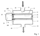
- Fig. 1 shows a schematic cross-section of an embodiment of an electrochemical reactor according to the invention.
- the electrochemical reactor comprises a reaction chamber 50, which can be made of metal sheet or the like.
- the chamber is provided with an inlet 20 for introduction of a fluid containing a material 21 being insoluble in the fluid.
- the chamber is furthermore provided with an outlet 40 for discharge of the fluid which contains the converted material.
- the internal circuit is situated in the reaction chamber, which circuit is suspended electrically insulated from the chamber by insulating suspensions 53, which at the same time shuts off the fluid flow.
- the internal circuit consists of a working electrode 12, a counter-electrode 13, and an ion-selective solid-state electrolyte 11 which selectively is capable of conducting ions between the working electrode and the counter-electrode.
- An exhaust gas from an internal combustion engine, and the unburnt carbon-containing material, primarily in the form of soot particles 21, in the exhaust gas are passed into the reactor through the inlet 20 (shown by the upper arrow), whereafter the exhaust gas and the converted material are conducted out through the outlet 40.
- the working electrode 12 and the counter-electrode 13 are different, but they may be identical.
- the working electrode consists of a 0,05-1 mm thick porous metallic layer with a number of pores and pore sizes ensuring a sufficiently large surface area and allowing passage of particles having the preferred size.
- the working electrode typically had a pore size of 20-40 ⁇ m and a pore density of 1000 pores per cm 2 working electrode area.
- the ion-selective electrolyte is a porous solid-state oxygen ion-conductor of cerium oxide doped with 20 % gadolinium oxide delivered from Seattle Speciality Ceramics, Seattle, USA (now: Praxair Specialty Ceramics).
- the material was calcined at 1550°C for 3 hours, which resulted in a particle size of 5-10 ⁇ m, which after pressing and sintering at 1500 °C resulted in a pore size of 1-10 ⁇ m.
- the ion-selective electrolyte was a solid-state hydrogen ion-conductor of sulphonated perfluoropolymer delivered under the trade mark National® from the company DuPont and with a pore size of 1-10 ⁇ m.
- the internal circuit is via leads 301 and 302 connected to a current source 30, which either may be a direct current source or an alternating current source.
- the leads 301 and 302 are taken through the chamber wall via insulated feed throughs 51 and 52.
- the current source is a direct current source, where the working electrode acts as a positive anode, and the counter-electrode is a negative cathode.
- the working electrode and the counter-electrode will in principle be identical and act alternatingly as anode and cathode with a frequency corresponding to the frequency of the alternating current.
- the electrochemical reactions will be the same as when the current source is a direct current source.
- the voltage difference over the working electrode and the counter-electrode is chosen in such a way that there is sufficient activation energy for the preferred electrochemical processes to take place.
- the voltage difference is generally higher than 1 volt, typically 5 volts, to obtain a satisfactory conversion rate.
- the reactor is started by introducing the flue gas into the inlet 20, and at the same time applying a voltage of 5 volts over the working electrode 12 and the counter-electrode 13. It is not required that the temperature of the reactor in advance has been brought up to for example 250-300 °C, even though this would naturally be an advantage in order to get as high conversion rates as possible already from the start.
- the flue gas is continuously passed to the inlet 20.
- the flue gas passes through openings 14 in the porous working electrode, whereby the soot particles 21 being insoluble in the flue gas, in the area in which the working electrode and the ion-selective electrolyte touches on each other, are brought within the electrochemical reaction distance from the working electrode. Within this distance, the soot particles react with oxygen ions, which are delivered by the ion-selective electrolyte, and the excess electrons are transferred to the working electrode. By participating in one or more electrochemical processes in one or more process steps, the soot particles are converted into carbon dioxide.
- the size of the cavities in the ion-selective electrolyte is chosen in such a way that a suitable retention of the soot particles which pass through the openings in the working electrode to the electrolyte is achieved.
- a preferred conversion rate for a given particle size distribution is achieved by choosing the number and size of the cavities in the working electrode in such a way that a suitably large surface area is obtained in the reaction zone in which the soot particles can exchange electrons with the working electrode, and in which they can react with the preferred ions delivered from the ion-selective electrolyte.
- the insoluble soot particles are converted into carbon dioxide, which leaves the reactor with the flue gas 40.
- Fig. 2 shows an enlarged view of the rectangular section II shown in Fig. 1.
- Soot particles 21 of a suitable size penetrate into the pores 14 in the working electrode 12, where they are stopped by the smaller pores 15 in the electrolyte 11.
- the flue gas passes unhindered through the pores in the direction indicated by the arrow in both working electrode and in the ion-selective electrolyte.
- Soot particles 21, which are within the reaction distance from the working electrode are converted with oxygen ions, delivered from the ion-selective electrolyte 11, under conversion into carbon dioxide, which is conducted away with the flowing fluid.
- Soot particles having a size larger than the pore size in the working electrode cannot penetrate into the working electrode, and will therefore not be converted electrochemically.
- Fig. 3 shows an enlarged view of the circular section III shown in Fig. 2.
- a soot particle 21 is situated in a pore 14 of the working electrode 12, which touches on the ion-selective electrolyte 13, whereby the soot particle 21 is "caught" within an open cavity, the open delimitation of which communicates with the flue gas.
- the soot particle can hereby be converted electrochemically by exchange of electrons with the working electrode 12, oxygen ions with the electrolyte 11, and carbon dioxide with the flue gas within and outside the cavity.
- oxygen content in the flue gas is very low, it might be necessary to add extra air, for example through a side channel in the chamber (not shown). Analogously, extra water or other reactants can be added, which originally are not present in sufficient amounts in the fluid.
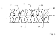
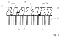
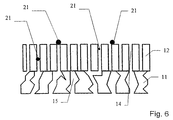
- Figs. 4, 5 and 6 show schematically alternative embodiments of the working electrode and the ion-selective electrolyte.
- Fig. 4 shows an embodiment in which the working electrode 12 as well as the ion-selective electrolyte 11 have openings for conducting the fluid in the form of pores 14 and 15, which have uneven delimitations in stead of the comparatively straight channels shown in Fig. 2.
- Figs. 5 and 6 show two alternative embodiments of the working electrode and the ion-selective electrolyte, in which the delimitations of the cavities are uneven and straight, respectively.
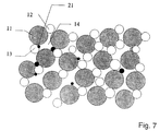
- Fig. 7 shows a schematic view of an embodiment of the internal circuit which comprises a porous mixed ion-selective electrolyte and electrode material.
- the internal circuit is constructed of comparatively large particles of the ion-conducting electrolyte 11 mixed with comparatively small particles of the working electrode material 12 and counter-electrode material 13, which here are shown as being identical.
- the mixed ion-selective electrolyte and electrode material functions as a stack of small electrochemical reactors which are electrically connected in series and in parallel, and in which the working electrode particles 12 for a small reactor at the same time will act as counter-electrode particles 13 for another small reactor.
- soot particles 21 are trapped in the cavities 14 in the porous structure, in which they are converted electrochemically as described in the discussion of Fig. 3.
- the flue gas and the converted soot particles which are the product of the electrochemical conversion, can pass through the pores in the mixed structure.
- Fig 8 shows a schematic view of an embodiment of the internal circuit, shown in Fig. 7, in which the porous mixed ion-selective electrolyte and electrode material is supported on a porous, inert carrier 16 with openings or channels 161 through which the fluid can be conducted away.
- the porous carrier material allows the fluid to pass, while it retains the insoluble material 21, which in this way can be converted electrochemically to soluble material in the reactive part of the reactor.
- Fig.9 shows a microphotograph taken on a scanning electron microscope of an electrochemical reactor constructed according to the principle shown in Fig. 7.
- ion-selective electrolyte material use has been made of cerium oxide doped with 20 atomic-% gadolinium oxide (CGO), which is an oxygen ion conductor, and as electrode material use is made of lanthanum manganite doped with 20 atomic-% strontium oxide (LSM).
- CGO gadolinium oxide
- LSM lanthanum manganite doped with 20 atomic-% strontium oxide
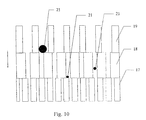
- Fig. 10 shows a schematic view of an embodiment of the internal circuit, in which the reaction section is constructed of a layered structure of three layers, each having the structure described in Fig. 7.
- the average pore size is so small that the smallest particles of the insoluble material are trapped and converted electrochemically.
- the intermediate layer 18 has a somewhat larger pore size, which allows the smallest particles 21 to penetrate the structure, while the larger particles are trapped.
- the largest particles are converted in the upper layer 19, which has a large pore size.
- Such a layered structure can be constructed using raw powders with different particle size in the various layers.
- the pore size in the final structure gets larger.
- the layered structure of the internal circuit can be composed of fewer than as well as more than three layers.
- Electrochemical reactor with internal circuit constructed as a sandwich structure of working electrode, ionselective electrolyte, and counter-electrode
- an ion-selective electrolyte was produced from cerium oxide doped with 20 atomic-% gadolinium oxide (hereinafter designated CGO) from Seattle Specialty Ceramics, Seattle, USA (now: Praxair Specialty Ceramics).
- CGO cerium oxide doped with 20 atomic-% gadolinium oxide
- the particle size of the powder was adjusted by heat treatment at 1550 °C for 3 hours, whereby an average particle size of the powder of 5-10 ⁇ m was obtained.
- the measuring of the particle size was made by electron scanning microscopy.
- the powder was pressed to a plate with a thickness of 1.5 mm at 100 MPa and sintered at 1500 °C for one hour.
- porous ion-selective electrolyte hereby obtained was provided with porous platinum electrodes by painting with a brush with a platinum paste delivered under the trade mark Demetron® M8005, Degussa, Germany, whereafter the ion-selective electrolyte with electrodes was sintered at 800 °C for one hour.
- the pore size of both electrodes and the ion-selective electrolyte was 0.5-5 ⁇ m.
- the internal circuit hereby constructed was provided with leads on the electrodes, connected to a laboratory current source of brand Danica TPS 23A, +/- 30 V, 2 A, regulated voltage.
- the complete set-up was then placed in a furnace and heated to about 300 °C in a gas flow of 20 % oxygen in nitrogen, to which was added carbon black of the type Printex® L delivered from Degussa, Germany.
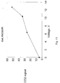
- Fig. 11 shows the measured generation of carbon dioxide as function of the applied direct voltage over an internal circuit.
- the porous, layered structure which corresponds to the structure shown in Fig. 4.
- the data shown have been measured with a mass spectrometer in the outlet flow, corresponding to the outlet 40 in Fig. 1, at a furnace temperature of 300 °C.
- Electrochemical reactor with internal circuit composed of a mixed ion-selective electrolyte and electrode material
- Heat-treated CGO-powder produced as described in example 1, was mixed with a similarly heat-treated powder of lanthanum manganite doped with 20 atomic-% strontium from Seattle Specialty Ceramics, Seattle, USA (now: Praxair Specialty Ceramics) (hereinafter designated LSM), which had been heat-treated at 1200 °C for 3 hours.
- LSM lanthanum manganite doped with 20 atomic-% strontium from Seattle Specialty Ceramics, Seattle, USA
- the powder mixture which contained 6.5 weight % LSM corresponding to about 6 volume %, was pressed to a plate at 100 MPa and sintered at 800 °C for 1 hour. After the sintering, the pore size in the sintered material was 0.4-4 ⁇ m.
- the plate was mounted in the same furnace as described in example 1, but without being provided with platinum electrodes, corresponding to the internal circuit shown in Fig. 7.
- Fig. 12 shows the measured generation of carbon dioxide as function of the applied voltage over the internal circuit.
- the reaction rate is higher because of the significantly higher effective surface area, where the reaction can proceed.
- the frequency area used from 0 to 400 Hz, a slight, but not marked increase in the conversion rate is detected, when the frequency is increased.
- the increase is highest in the frequency area from 0 to about 20 Hz, whereafter the conversion rate is almost constant.
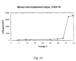
- a mixture of CGO-powder and LSM-powder was prepared as described in example 2.
- the mixture was dispersed in ethanol using a dispersing agent, KD-4 from the company ICI, whereafter it was deposited on an inert carrier of non-woven quartz fibres.
- the deposited powder mixture and carrier were then sintered at 800 °C for 2 hours, whereafter both were placed in a furnace, as described in example 1.
- cerium oxide doped with 10 atomic % gadolinium oxide (afterwards designated as CGO-10) from Praxair Specialty Ceramics, Seattle, USA (former: Seattle Specialty Ceramics) was used as oxide ion conducting electrolyte material.
- the CGO-10-powder was heat treated at 1500°C for 3 hours to adjust the particle size.
- the CGO-10 powder was mixed with 5 weight % LSM-powder corresponding to about 4.5 volume % as described in example 2.
- the sintered plates were provided with contacts for current leads by painting silver paste (Demetron, Leitsilber 200, Prod. No. 6200 0007) on their surfaces as shown in fig. 13.
- the silver leads 203 were placed at opposite edges.
- the silver leads 204 were placed in an intermittent pattern, providing a significantly shorter current path than that for the first plate 201.
- the silver leads were contacted with wire connected to an AC power supply, fixed at 50 Hz and variable from 2 to 250 V (RKT-2, IMPO electronic A/S, Odense, Denmark).
- the plates were tested one by one in a furnace as described in example 2.
- Soot collected from the exhaust system of a diesel engine was added to the gas stream through the reactor.
- the CO 2 -evolution was monitored by leading the exhaust gas from the reactor (equivalent to the outlet 40 in Fig. 1) through a gas flow-cell in a Fourier transform infrared spectrometer.
- Fig. 14 shows the generation of carbon dioxide as function of the applied 50 Hz AC voltage over the first plate 201. It is seen that the generation of carbon dioxide increases sharply at a threshold voltage of about 150 V.
- Fig. 15 shows the generation of carbon dioxide as a function of the applied 50 Hz AC voltage over the second plate 202. It is seen that the generation of carbon dioxide increases sharply at a threshold voltage of about 35 V, i.e. at a lower voltage than for plate 201, corresponding to the shorter current path provided by the intermittent silver lead pattern.
- An electrochemical reactor was constructed with an internal circuit comprising a hydrogen ion-conducting selective electrolyte of a perfluorated sulphonate membrane of type National® from the company DuPont.
- the electrolyte was provided with porous electrodes by painting with platinum paste as described in example 1.
- a dispersion of 1 % oil in water was conducted through the reactor, the flowing water and the reactor being heated to about 90 °C in a furnace in order hereby to increase the reaction rate.
- the water could pass the reactor, whereas the oil droplets were trapped and converted electrochemically into carbon dioxide.
- the basis may be a diesel engine, which continuously delivers 180 kW and typically produces 0.3 g soot per kWh corresponding to a soot production m of 0.015 g/s.
Landscapes
- Chemical & Material Sciences (AREA)
- Engineering & Computer Science (AREA)
- Thermal Sciences (AREA)
- Chemical Kinetics & Catalysis (AREA)
- Physics & Mathematics (AREA)
- Mechanical Engineering (AREA)
- General Engineering & Computer Science (AREA)
- Combustion & Propulsion (AREA)
- Health & Medical Sciences (AREA)
- Toxicology (AREA)
- Physical Or Chemical Processes And Apparatus (AREA)
- Water Treatment By Electricity Or Magnetism (AREA)
- Carbon And Carbon Compounds (AREA)
- Electrodes For Compound Or Non-Metal Manufacture (AREA)
Priority Applications (1)
| Application Number | Priority Date | Filing Date | Title |
|---|---|---|---|
| SI9730149T SI0914203T1 (en) | 1996-05-20 | 1997-05-20 | A method and a reactor for electrochemical conversion of a material e.g. soot particles being insoluble in a fluid |
Applications Claiming Priority (5)
| Application Number | Priority Date | Filing Date | Title |
|---|---|---|---|
| DK58796 | 1996-05-20 | ||
| DK58796 | 1996-05-20 | ||
| US3544997P | 1997-01-16 | 1997-01-16 | |
| US35449P | 1997-01-16 | ||
| PCT/DK1997/000229 WO1997044126A1 (en) | 1996-05-20 | 1997-05-20 | A method and a reactor for electrochemical conversion of a material e.g. soot particles being insoluble in a fluid |
Publications (2)
| Publication Number | Publication Date |
|---|---|
| EP0914203A1 EP0914203A1 (en) | 1999-05-12 |
| EP0914203B1 true EP0914203B1 (en) | 2001-03-21 |
Family
ID=26064263
Family Applications (1)
| Application Number | Title | Priority Date | Filing Date |
|---|---|---|---|
| EP97923836A Expired - Lifetime EP0914203B1 (en) | 1996-05-20 | 1997-05-20 | A method and a reactor for electrochemical conversion of a material e.g. soot particles being insoluble in a fluid |
Country Status (20)
| Country | Link |
|---|---|
| US (1) | US6036840A (no) |
| EP (1) | EP0914203B1 (no) |
| JP (1) | JP2000514344A (no) |
| CN (1) | CN1089629C (no) |
| AT (1) | ATE199842T1 (no) |
| AU (1) | AU720113B2 (no) |
| BR (1) | BR9709323A (no) |
| CA (1) | CA2255083C (no) |
| DE (1) | DE69704361T2 (no) |
| DK (1) | DK0914203T3 (no) |
| ES (1) | ES2157575T3 (no) |
| GR (1) | GR3036086T3 (no) |
| HK (1) | HK1020023A1 (no) |
| HU (1) | HU224056B1 (no) |
| NO (1) | NO317410B1 (no) |
| NZ (1) | NZ332774A (no) |
| PL (1) | PL330011A1 (no) |
| PT (1) | PT914203E (no) |
| TR (1) | TR199802365T2 (no) |
| WO (1) | WO1997044126A1 (no) |
Families Citing this family (25)
| Publication number | Priority date | Publication date | Assignee | Title |
|---|---|---|---|---|
| US6200531B1 (en) * | 1998-05-11 | 2001-03-13 | Igen International, Inc. | Apparatus for carrying out electrochemiluminescence test measurements |
| US6284196B1 (en) * | 1999-04-01 | 2001-09-04 | Bp Corporation North America Inc. | Apparatus for monitor and control of an ammoxidation reactor with a fourier transform infrared spectrometer |
| US20050016864A1 (en) * | 2001-05-22 | 2005-01-27 | Henrik Christensen | Method and apparatus for electrochemical reduction of nitrogen oxides in a mixture of nitrogen oxides and oxygen |
| US6425757B1 (en) * | 2001-06-13 | 2002-07-30 | Abb Lummus Global Inc. | Pyrolysis heater with paired burner zoned firing system |
| DE10155791C1 (de) * | 2001-11-14 | 2003-07-17 | Starck H C Gmbh | Verfahren zum elektrochemischen Aufschluss von Superlegierungen |
| JP2005530183A (ja) * | 2002-06-20 | 2005-10-06 | バイオヴェリス コーポレイション | エレクトロケミルミネッセンス・フローセル及びフローセル部品 |
| JP4660724B2 (ja) * | 2004-12-21 | 2011-03-30 | 学校法人立命館 | 浄化装置、浄化方法、及び、排出ガス浄化システム |
| JP5614521B2 (ja) * | 2005-01-24 | 2014-10-29 | 独立行政法人産業技術総合研究所 | 固体炭素分解型セラミックス化学反応装置 |
| JP5590796B2 (ja) | 2005-06-03 | 2014-09-17 | ボード・オブ・リージェンツ・オブ・ザ・ユニバーシティ・オブ・テキサス・システム | 電気化学および単一ファラデー電極による電気化学発光 |
| JP2008546626A (ja) * | 2005-06-23 | 2008-12-25 | ジーアールディーシー,エルエルシー | 水素の効率的な生産 |
| DE102006001831A1 (de) * | 2006-01-13 | 2007-09-20 | Emitec Gesellschaft Für Emissionstechnologie Mbh | Verfahren und Vorrichtung zur Verringerung der Partikelanzahl im Abgas einer Verbrennungskraftmaschine |
| JP2008119618A (ja) * | 2006-11-14 | 2008-05-29 | Ritsumeikan | 浄化装置、浄化方法、排出ガス浄化システム、及び浄化構造体の製造方法 |
| JP2009125622A (ja) * | 2007-11-20 | 2009-06-11 | Toyota Industries Corp | 排気ガスの浄化装置 |
| DE102007056423A1 (de) * | 2007-11-23 | 2009-06-04 | Süd-Chemie AG | Herstellung und Verwendung neuer Polyaniline zur Wasserbehandlung |
| JP2009138522A (ja) * | 2007-12-03 | 2009-06-25 | Toyota Industries Corp | 排気ガスの浄化装置 |
| JP4525748B2 (ja) * | 2007-12-20 | 2010-08-18 | 株式会社豊田自動織機 | 排気ガス処理装置 |
| JP2010029796A (ja) * | 2008-07-29 | 2010-02-12 | National Institute Of Advanced Industrial & Technology | カーボン除去装置およびカーボンを除去する方法 |
| JP2010180799A (ja) * | 2009-02-06 | 2010-08-19 | Toyota Industries Corp | 排気ガス浄化装置 |
| CA2830383A1 (en) * | 2011-04-12 | 2012-10-18 | Richard Max MANDLE | Centrifugal fluid ring reactor |
| US9475996B2 (en) | 2012-10-17 | 2016-10-25 | Richard Max Mandle | Centrifugal fluid ring plasma reactor |
| JP6300753B2 (ja) * | 2015-03-31 | 2018-03-28 | 日本電信電話株式会社 | N2o分析装置および分析方法 |
| CN110975540A (zh) * | 2018-12-30 | 2020-04-10 | 熵零技术逻辑工程院集团股份有限公司 | 一种动力装置 |
| CN110180385B (zh) * | 2019-06-19 | 2021-09-24 | 沈阳理工大学 | 多孔陶瓷催化氧化器及其制法、多用途高效空气净化装置 |
| CN111282410B (zh) * | 2020-02-19 | 2021-07-06 | 华中师范大学 | 电化学法降解气态污染物的装置及其方法 |
| CN113354194A (zh) * | 2021-06-04 | 2021-09-07 | 清华大学 | 协同处理印刷废气废水装置及处理印刷废气废水的方法 |
Family Cites Families (13)
| Publication number | Priority date | Publication date | Assignee | Title |
|---|---|---|---|---|
| US4310406A (en) * | 1968-10-01 | 1982-01-12 | Resource Control, Incorporated | Apparatus for removing metal ions and other pollutants from aqueous solutions and moist gaseous streams |
| US5022975A (en) * | 1985-11-12 | 1991-06-11 | 16R Enterprises, Inc. | Solid state electrochemical pollution control device |
| CN2039995U (zh) * | 1987-04-14 | 1989-06-28 | 姜万兴 | 电化学空气分离装置 |
| DE3739580A1 (de) * | 1987-11-23 | 1989-06-01 | Battelle Institut E V | Verfahren und vorrichtung zur spaltung eines dispersen systems in einer elektrochemischen zelle |
| DE3809307A1 (de) * | 1988-03-19 | 1989-09-28 | Veba Oel Ag | Motorschmieroel fuer dieselmotoren und verfahren zum betreiben eines dieselmotors |
| US4902487A (en) * | 1988-05-13 | 1990-02-20 | Johnson Matthey, Inc. | Treatment of diesel exhaust gases |
| DE4130378A1 (de) * | 1991-09-12 | 1993-03-18 | Eberspaecher J | Vorrichtung zur thermischen regeneration von partikelfiltern fuer dieselmotorenabgas |
| DE4236711A1 (en) * | 1991-11-02 | 1993-05-06 | Abb Patent Gmbh, 6800 Mannheim, De | Particulate soot determination e.g. for combustion gases - from EMF variation induced by deposition on an electrode in a solid electrolyte cell |
| US5457945A (en) * | 1992-01-07 | 1995-10-17 | Pall Corporation | Regenerable diesel exhaust filter and heater |
| EP0577026A2 (en) * | 1992-06-29 | 1994-01-05 | Yoshiaki Nagaura | Filtration method and filter device |
| US5388400A (en) * | 1992-12-30 | 1995-02-14 | Donaldson Company, Inc. | Diesel engine exhaust regenerable filter system |
| US5401372A (en) * | 1993-04-26 | 1995-03-28 | Ceramatec, Inc. | Electrochemical catalytic reduction cell for the reduction of NOx in an O2 -containing exhaust emission |
| KR950000197A (ko) * | 1993-06-02 | 1995-01-03 | 히데오 요시카와 | 오염공기용 정화장치 |
-
1997
- 1997-05-20 DE DE69704361T patent/DE69704361T2/de not_active Expired - Fee Related
- 1997-05-20 TR TR1998/02365T patent/TR199802365T2/xx unknown
- 1997-05-20 PT PT97923836T patent/PT914203E/pt unknown
- 1997-05-20 NZ NZ332774A patent/NZ332774A/xx unknown
- 1997-05-20 CA CA002255083A patent/CA2255083C/en not_active Expired - Fee Related
- 1997-05-20 PL PL97330011A patent/PL330011A1/xx unknown
- 1997-05-20 EP EP97923836A patent/EP0914203B1/en not_active Expired - Lifetime
- 1997-05-20 CN CN97194824A patent/CN1089629C/zh not_active Expired - Fee Related
- 1997-05-20 DK DK97923836T patent/DK0914203T3/da active
- 1997-05-20 AT AT97923836T patent/ATE199842T1/de not_active IP Right Cessation
- 1997-05-20 WO PCT/DK1997/000229 patent/WO1997044126A1/en active IP Right Grant
- 1997-05-20 HU HU9903107A patent/HU224056B1/hu not_active IP Right Cessation
- 1997-05-20 ES ES97923836T patent/ES2157575T3/es not_active Expired - Lifetime
- 1997-05-20 JP JP09541413A patent/JP2000514344A/ja not_active Ceased
- 1997-05-20 BR BR9709323-8A patent/BR9709323A/pt not_active IP Right Cessation
- 1997-05-20 AU AU29513/97A patent/AU720113B2/en not_active Ceased
-
1998
- 1998-11-17 NO NO19985356A patent/NO317410B1/no unknown
- 1998-11-19 US US09/195,906 patent/US6036840A/en not_active Expired - Fee Related
-
1999
- 1999-11-11 HK HK99105215A patent/HK1020023A1/xx not_active IP Right Cessation
-
2001
- 2001-06-19 GR GR20010400931T patent/GR3036086T3/el not_active IP Right Cessation
Also Published As
| Publication number | Publication date |
|---|---|
| PT914203E (pt) | 2001-08-30 |
| AU720113B2 (en) | 2000-05-25 |
| NO985356D0 (no) | 1998-11-17 |
| AU2951397A (en) | 1997-12-09 |
| CA2255083A1 (en) | 1997-11-27 |
| EP0914203A1 (en) | 1999-05-12 |
| HUP9903107A2 (hu) | 2001-05-28 |
| DK0914203T3 (da) | 2001-07-23 |
| ATE199842T1 (de) | 2001-04-15 |
| NO317410B1 (no) | 2004-10-25 |
| HUP9903107A3 (en) | 2002-02-28 |
| CA2255083C (en) | 2006-10-24 |
| TR199802365T2 (xx) | 1999-03-22 |
| HU224056B1 (hu) | 2005-05-30 |
| ES2157575T3 (es) | 2001-08-16 |
| GR3036086T3 (en) | 2001-09-28 |
| PL330011A1 (en) | 1999-04-26 |
| DE69704361D1 (de) | 2001-04-26 |
| NO985356L (no) | 1998-11-17 |
| DE69704361T2 (de) | 2001-09-20 |
| US6036840A (en) | 2000-03-14 |
| CN1219139A (zh) | 1999-06-09 |
| JP2000514344A (ja) | 2000-10-31 |
| HK1020023A1 (en) | 2000-03-10 |
| NZ332774A (en) | 2000-05-26 |
| BR9709323A (pt) | 2000-01-04 |
| WO1997044126A1 (en) | 1997-11-27 |
| CN1089629C (zh) | 2002-08-28 |
Similar Documents
| Publication | Publication Date | Title |
|---|---|---|
| EP0914203B1 (en) | A method and a reactor for electrochemical conversion of a material e.g. soot particles being insoluble in a fluid | |
| US6183609B1 (en) | Sintered laminated structures, electrochemical cells and process for producing such sintered laminated structures | |
| US20090004072A1 (en) | Ceramic Chemical Reaction Device Capable of Decomposing Solid Carbon | |
| US7553573B2 (en) | Solid state electrochemical composite | |
| US6824907B2 (en) | Tubular solid oxide fuel cell stack | |
| US7736772B2 (en) | Tubular solid oxide fuel cell stack | |
| US5401372A (en) | Electrochemical catalytic reduction cell for the reduction of NOx in an O2 -containing exhaust emission | |
| US4463065A (en) | Fuel cell and method for conducting gas-phase oxidation | |
| EP0245494A1 (en) | Solid state electrochemical pollution control device | |
| US20100287916A1 (en) | Purification structure incorporating a biased electrochemical catalyst system | |
| WO2008059888A1 (fr) | Appareil de purification, procédé de purification, système de purification de gaz d'échappement, et procédé de production de structure de purification | |
| EP3030341B1 (en) | Method and system for the purification of exhaust gas with an electrochemical cell | |
| JP5252362B2 (ja) | セラミック電極 | |
| JP2013233504A (ja) | 排ガス浄化装置 | |
| JP2008307493A (ja) | 自己組織的多孔質化薄膜型電気化学リアクター | |
| KR100478427B1 (ko) | 유체에불용성인매연입자등의물질의전기화학적전환을위한반응기및그의방법 | |
| MXPA98009743A (en) | A method for the electrochemical conversion of a material that is insoluble in a fluid in a material that is soluble in the flu | |
| JP3948170B2 (ja) | 排ガス浄化用電気化学触媒 | |
| Dinesen et al. | Electrochemical diesel particulate filter | |
| JPH07275714A (ja) | NOx除去装置 | |
| JPH06267571A (ja) | 固体電解質型燃料電池 | |
| Hendriksen et al. | Cheap Thin Film Oxygen Membranes |
Legal Events
| Date | Code | Title | Description |
|---|---|---|---|
| PUAI | Public reference made under article 153(3) epc to a published international application that has entered the european phase |
Free format text: ORIGINAL CODE: 0009012 |
|
| 17P | Request for examination filed |
Effective date: 19981116 |
|
| AK | Designated contracting states |
Kind code of ref document: A1 Designated state(s): AT BE CH DE DK ES FI FR GB GR IE IT LI LU MC NL PT SE |
|
| AX | Request for extension of the european patent |
Free format text: AL PAYMENT 19981116;LT PAYMENT 19981116;LV PAYMENT 19981116;RO PAYMENT 19981116;SI PAYMENT 19981116 |
|
| GRAG | Despatch of communication of intention to grant |
Free format text: ORIGINAL CODE: EPIDOS AGRA |
|
| 17Q | First examination report despatched |
Effective date: 19990930 |
|
| GRAG | Despatch of communication of intention to grant |
Free format text: ORIGINAL CODE: EPIDOS AGRA |
|
| GRAG | Despatch of communication of intention to grant |
Free format text: ORIGINAL CODE: EPIDOS AGRA |
|
| GRAH | Despatch of communication of intention to grant a patent |
Free format text: ORIGINAL CODE: EPIDOS IGRA |
|
| GRAH | Despatch of communication of intention to grant a patent |
Free format text: ORIGINAL CODE: EPIDOS IGRA |
|
| GRAA | (expected) grant |
Free format text: ORIGINAL CODE: 0009210 |
|
| AK | Designated contracting states |
Kind code of ref document: B1 Designated state(s): AT BE CH DE DK ES FI FR GB GR IE IT LI LU MC NL PT SE |
|
| AX | Request for extension of the european patent |
Free format text: AL PAYMENT 19981116;LT PAYMENT 19981116;LV PAYMENT 19981116;RO PAYMENT 19981116;SI PAYMENT 19981116 |
|
| REF | Corresponds to: |
Ref document number: 199842 Country of ref document: AT Date of ref document: 20010415 Kind code of ref document: T |
|
| REG | Reference to a national code |
Ref country code: CH Ref legal event code: EP |
|
| REG | Reference to a national code |
Ref country code: IE Ref legal event code: FG4D |
|
| REF | Corresponds to: |
Ref document number: 69704361 Country of ref document: DE Date of ref document: 20010426 |
|
| ET | Fr: translation filed | ||
| ITF | It: translation for a ep patent filed |
Owner name: PORTA CHECCACCI & ASSOCIATI S.P.A. |
|
| REG | Reference to a national code |
Ref country code: CH Ref legal event code: NV Representative=s name: AMMANN PATENTANWAELTE AG BERN |
|
| REG | Reference to a national code |
Ref country code: DK Ref legal event code: T3 |
|
| REG | Reference to a national code |
Ref country code: ES Ref legal event code: FG2A Ref document number: 2157575 Country of ref document: ES Kind code of ref document: T3 |
|
| REG | Reference to a national code |
Ref country code: GB Ref legal event code: IF02 |
|
| PLBE | No opposition filed within time limit |
Free format text: ORIGINAL CODE: 0009261 |
|
| STAA | Information on the status of an ep patent application or granted ep patent |
Free format text: STATUS: NO OPPOSITION FILED WITHIN TIME LIMIT |
|
| 26N | No opposition filed | ||
| REG | Reference to a national code |
Ref country code: SI Ref legal event code: IF |
|
| PGFP | Annual fee paid to national office [announced via postgrant information from national office to epo] |
Ref country code: LU Payment date: 20080604 Year of fee payment: 12 Ref country code: ES Payment date: 20080605 Year of fee payment: 12 Ref country code: DK Payment date: 20080530 Year of fee payment: 12 Ref country code: DE Payment date: 20080529 Year of fee payment: 12 Ref country code: CH Payment date: 20080527 Year of fee payment: 12 |
|
| PGFP | Annual fee paid to national office [announced via postgrant information from national office to epo] |
Ref country code: AT Payment date: 20080529 Year of fee payment: 12 |
|
| PGFP | Annual fee paid to national office [announced via postgrant information from national office to epo] |
Ref country code: MC Payment date: 20080529 Year of fee payment: 12 Ref country code: PT Payment date: 20080520 Year of fee payment: 12 Ref country code: FI Payment date: 20080530 Year of fee payment: 12 |
|
| PGFP | Annual fee paid to national office [announced via postgrant information from national office to epo] |
Ref country code: SE Payment date: 20080530 Year of fee payment: 12 Ref country code: NL Payment date: 20080526 Year of fee payment: 12 Ref country code: IE Payment date: 20080603 Year of fee payment: 12 |
|
| PGFP | Annual fee paid to national office [announced via postgrant information from national office to epo] |
Ref country code: IT Payment date: 20080531 Year of fee payment: 12 Ref country code: FR Payment date: 20080530 Year of fee payment: 12 |
|
| PGFP | Annual fee paid to national office [announced via postgrant information from national office to epo] |
Ref country code: GB Payment date: 20080521 Year of fee payment: 12 |
|
| PGFP | Annual fee paid to national office [announced via postgrant information from national office to epo] |
Ref country code: BE Payment date: 20080701 Year of fee payment: 12 |
|
| PGFP | Annual fee paid to national office [announced via postgrant information from national office to epo] |
Ref country code: GR Payment date: 20080530 Year of fee payment: 12 |
|
| BERE | Be: lapsed |
Owner name: *DINEX A/S Effective date: 20090531 |
|
| REG | Reference to a national code |
Ref country code: PT Ref legal event code: MM4A Free format text: LAPSE DUE TO NON-PAYMENT OF FEES Effective date: 20091120 |
|
| LTLA | Lt: lapse of european patent or patent extension |
Effective date: 20090520 |
|
| PG25 | Lapsed in a contracting state [announced via postgrant information from national office to epo] |
Ref country code: MC Free format text: LAPSE BECAUSE OF NON-PAYMENT OF DUE FEES Effective date: 20090531 |
|
| REG | Reference to a national code |
Ref country code: CH Ref legal event code: PL |
|
| REG | Reference to a national code |
Ref country code: DK Ref legal event code: EBP |
|
| GBPC | Gb: european patent ceased through non-payment of renewal fee |
Effective date: 20090520 |
|
| PG25 | Lapsed in a contracting state [announced via postgrant information from national office to epo] |
Ref country code: LI Free format text: LAPSE BECAUSE OF NON-PAYMENT OF DUE FEES Effective date: 20090531 Ref country code: FI Free format text: LAPSE BECAUSE OF NON-PAYMENT OF DUE FEES Effective date: 20090520 Ref country code: CH Free format text: LAPSE BECAUSE OF NON-PAYMENT OF DUE FEES Effective date: 20090531 Ref country code: AT Free format text: LAPSE BECAUSE OF NON-PAYMENT OF DUE FEES Effective date: 20090520 |
|
| NLV4 | Nl: lapsed or anulled due to non-payment of the annual fee |
Effective date: 20091201 |
|
| PG25 | Lapsed in a contracting state [announced via postgrant information from national office to epo] |
Ref country code: NL Free format text: LAPSE BECAUSE OF NON-PAYMENT OF DUE FEES Effective date: 20091201 |
|
| REG | Reference to a national code |
Ref country code: FR Ref legal event code: ST Effective date: 20100129 Ref country code: SI Ref legal event code: KO00 Effective date: 20100114 |
|
| REG | Reference to a national code |
Ref country code: IE Ref legal event code: MM4A |
|
| PG25 | Lapsed in a contracting state [announced via postgrant information from national office to epo] |
Ref country code: PT Free format text: LAPSE BECAUSE OF NON-PAYMENT OF DUE FEES Effective date: 20091120 |
|
| PG25 | Lapsed in a contracting state [announced via postgrant information from national office to epo] |
Ref country code: IE Free format text: LAPSE BECAUSE OF NON-PAYMENT OF DUE FEES Effective date: 20090520 Ref country code: FR Free format text: LAPSE BECAUSE OF NON-PAYMENT OF DUE FEES Effective date: 20090602 Ref country code: DK Free format text: LAPSE BECAUSE OF NON-PAYMENT OF DUE FEES Effective date: 20090531 |
|
| PG25 | Lapsed in a contracting state [announced via postgrant information from national office to epo] |
Ref country code: GB Free format text: LAPSE BECAUSE OF NON-PAYMENT OF DUE FEES Effective date: 20090520 |
|
| PG25 | Lapsed in a contracting state [announced via postgrant information from national office to epo] |
Ref country code: GR Free format text: LAPSE BECAUSE OF NON-PAYMENT OF DUE FEES Effective date: 20091202 Ref country code: DE Free format text: LAPSE BECAUSE OF NON-PAYMENT OF DUE FEES Effective date: 20091201 Ref country code: BE Free format text: LAPSE BECAUSE OF NON-PAYMENT OF DUE FEES Effective date: 20090531 |
|
| REG | Reference to a national code |
Ref country code: ES Ref legal event code: FD2A Effective date: 20090521 |
|
| PG25 | Lapsed in a contracting state [announced via postgrant information from national office to epo] |
Ref country code: ES Free format text: LAPSE BECAUSE OF NON-PAYMENT OF DUE FEES Effective date: 20090521 |
|
| PG25 | Lapsed in a contracting state [announced via postgrant information from national office to epo] |
Ref country code: IT Free format text: LAPSE BECAUSE OF NON-PAYMENT OF DUE FEES Effective date: 20090520 |
|
| PG25 | Lapsed in a contracting state [announced via postgrant information from national office to epo] |
Ref country code: LU Free format text: LAPSE BECAUSE OF NON-PAYMENT OF DUE FEES Effective date: 20090520 |
|
| PG25 | Lapsed in a contracting state [announced via postgrant information from national office to epo] |
Ref country code: SE Free format text: LAPSE BECAUSE OF NON-PAYMENT OF DUE FEES Effective date: 20090521 |