EP0913670B1 - Ultraschall-durchflussmesser - Google Patents
Ultraschall-durchflussmesser Download PDFInfo
- Publication number
- EP0913670B1 EP0913670B1 EP98914045A EP98914045A EP0913670B1 EP 0913670 B1 EP0913670 B1 EP 0913670B1 EP 98914045 A EP98914045 A EP 98914045A EP 98914045 A EP98914045 A EP 98914045A EP 0913670 B1 EP0913670 B1 EP 0913670B1
- Authority
- EP
- European Patent Office
- Prior art keywords
- ultrasonic
- section
- flow measurement
- measurement section
- wave
- Prior art date
- Legal status (The legal status is an assumption and is not a legal conclusion. Google has not performed a legal analysis and makes no representation as to the accuracy of the status listed.)
- Expired - Lifetime
Links
Images


Classifications
-
- G—PHYSICS
- G01—MEASURING; TESTING
- G01F—MEASURING VOLUME, VOLUME FLOW, MASS FLOW OR LIQUID LEVEL; METERING BY VOLUME
- G01F1/00—Measuring the volume flow or mass flow of fluid or fluent solid material wherein the fluid passes through a meter in a continuous flow
- G01F1/66—Measuring the volume flow or mass flow of fluid or fluent solid material wherein the fluid passes through a meter in a continuous flow by measuring frequency, phase shift or propagation time of electromagnetic or other waves, e.g. using ultrasonic flowmeters
- G01F1/662—Constructional details
Definitions
- the present invention relates to an ultrasonic flowmeter for measuring the flow of a fluid by use of an ultrasonic wave.
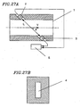
- ultrasonic flowmeters of the type described above is disclosed, for example, in Japanese Laid-Open Publication No. 8-233628 .
- this ultrasonic flowmeter as shown in Figures 27A and 27B , ultrasonic oscillators 2 and 3 are disposed facing each other in a portion of a flow path 1 which is a rectangle in section 4 .
- the speed of a fluid is calculated by a flow calculation means 5 using the difference between the propagation time in which an ultrasonic wave transmitted from the ultrasonic oscillator 2 is received by the ultrasonic oscillator 3 and the propagation time in which an ultrasonic wave transmitted from the ultrasonic oscillator 3 is received by the ultrasonic oscillator 2 .
- the flow rate distribution in the flow path 1 is presumed from the Reynolds number of the fluid, to obtain a correction coefficient and thus calculate the flow.
- the conventional ultrasonic flowmeter has the following problem.
- the propagation distance of a reflected wave which is reflected from the inside walls of the flow path is different from the propagation distance of a direct wave which propagates without being reflected.
- a phase difference is therefore generated between the reflected wave and the direct wave. Since a synthetic wave of the reflected wave and the direct wave is observed as a received wave, the amplitude of the received wave increases or decreases, and the period thereof varies, depending on the phase difference between the reflected wave and the direct wave. This narrows the measurement precision as well as the measurable flow range.
- EP-A-0631114 discloses the pre-characterizing features of the present invention.
- An advantage of the invention is that the influence of the phase difference between the direct wave and the reflected wave on the measurement results is reduced. Reducing the influence of the reflected wave in the measurement section of the flow path means that the measurement precision can be improved over a wide range. Also, embodiments of the invention enable such reduction of the influence of the reflected wave using a simple structure. Accordingly, the influence of the reflected wave in the flow measurement section can be reduced, to obtain a high-precision ultrasonic flowmeter.
- the ultrasonic flowmeter of the second embodiment according to the present invention for measuring a flow of a fluid by use of an ultrasonic wave, includes: a pair of ultrasonic oscillators; a measurement section for measuring a time in which an ultrasonic wave propagates between the pair of ultrasonic oscillators; and a calculation section for calculating the flow of the fluid flowing in a flow measurement section based on an output from the measurement section, wherein, in a configuration where a phase difference between a direct wave which propagates in the fluid flowing in the flow measurement section without being reflected from a wall of the flow measurement section and a reflected wave which is reflected from a wall of the flow measurement section influences a measurement result, the flow measurement section and the pair of ultrasonic oscillators are configured so that an influence of the phase difference between the direct wave and the reflected wave on the measurement result can be reduced. Accordingly, the influence of the reflected wave in the flow measurement section can be reduced, to obtain a high-precision ultrasonic flowmeter.
- the ultrasonic flowmeter of the third embodiment according to the present invention for measuring a flow of a fluid by use of ultrasonic wave, includes: a pair of ultrasonic oscillators; a measurement section for measuring a time in which an ultrasonic wave propagates between the pair of ultrasonic oscillators; and a calculation section for calculating the flow of the fluid flowing in a flow measurement section based on an output from the measurement section, wherein, in a configuration where a phase difference between a direct wave which propagates in the fluid flowing in the flow measurement section without being reflected from a wall of the flow measurement section and a reflected wave which is reflected from a wall of the flow measurement section influences a measurement result, parameters relating to a frequency of the pair of ultrasonic oscillators, a distance between the pair of ultrasonic oscillators, and a cross section shape of the flow measurement section are combined and characterized so that an influence of the phase difference between the direct wave and the reflected wave on the measurement result can be reduced. Accordingly, the influence of the reflected wave
- the direct wave is a wave which propagates along a straight line connecting centers of the pair of ultrasonic oscillators
- the reflected wave is a wave which propagates along two equal sides of an isosceles triangle formed by connecting the centers of the pair of ultrasonic oscillators and a point on a wall of the flow measurement section
- a propagation phase difference caused by a difference between a propagation distance of the direct wave and a propagation distance of the reflected wave is 3 ⁇ /2 or more. Accordingly, the influence of the reflected wave in the flow measurement section can be reduced with a simple structure, to obtain a high-precision ultrasonic flowmeter.
- the direct wave is a wave which propagates along a straight line connecting centers of the pair of ultrasonic oscillators
- the reflected wave is a wave which is reflected only once from a wall of the flow measurement section
- one side or a diameter of effective radiation surfaces of the pair of ultrasonic oscillators is shorter than a height of the flow measurement section so that a shortest propagation time of the reflected wave is longer than a propagation time of the direct wave. Accordingly, the influence of the reflected wave in the flow measurement section can be reduced with a simple structure, to obtain a high-precision ultrasonic flowmeter.
- a frequency of the pair of ultrasonic oscillators is set at a predetermined value or greater. Accordingly, the influence of the reflected wave in the flow measurement section can be reduced and the time resolution can be improved, to obtain a higher-precision ultrasonic flowmeter.
- the direct wave is a wave which propagates along a straight line connecting centers of the pair of ultrasonic oscillators
- the reflected wave is a wave which propagates along two equal sides of an isosceles triangle formed by connecting the centers of the pair of ultrasonic oscillators and a point on a wall of the flow measurement section
- a propagation phase difference between a propagation distance of the direct wave and a propagation distance of the reflected wave is 0.2 n or less. Accordingly, the influence of the reflected wave in the flow measurement section can be reduced with a simple structure, to obtain a high-precision ultrasonic flowmeter.
- the ultrasonic flowmeter of the eighth embodiment based on the ultrasonic flowmeter of the seventh embodiment, the ultrasonic flowmeter further includes at least one or more division plate for dividing the flow measurement section into a plurality of portions. Accordingly, the influence of the reflected wave in the flow measurement section can be reduced, to obtain a high-precision ultrasonic flowmeter.
- the frequency of the pair of ultrasonic oscillators is set at a predetermined value or less. Accordingly, the influence of the reflected wave in the flow measurement section can be reduced, to obtain a high-precision ultrasonic flowmeter.
- the sectional shape of the flow measurement section is a rectangle, and a parameter relating to the sectional shape of the flow measurement section is a height of the rectangle. Accordingly, the influence of the reflected wave in the flow measurement section can be reduced with a simple structure, to obtain a high-precision ultrasonic flowmeter.
- the sectional shape of the flow measurement section is a circle, and a parameter relating to the sectional shape of the flow measurement section is a diameter of the circle. Accordingly, the influence of the reflected wave in the flow measurement section can be reduced with a simple structure, to obtain a high-precision ultrasonic flowmeter.
- the pair of ultrasonic oscillators are disposed so that a line connecting centers of the pair of ultrasonic oscillators is shifted against a center line of the cross section of the flow measurement section in a predetermined direction. Accordingly, the influence of the reflected wave in the flow measurement section can be reduced, to obtain a high-precision ultrasonic flowmeter.
- the line connecting the centers of the pair of ultrasonic oscillators and the center line of the cross section of the flow measurement section in a predetermined direction are parallel with each other. Accordingly, the influence of the reflected wave in the flow measurement section can be reduced, to obtain a high-precision ultrasonic flowmeter.
- the line connecting the centers of the pair of ultrasonic oscillators and the center line of the cross section of the flow measurement section in a predetermined direction cross at a predetermined angle. Accordingly, the influence of the reflected wave in the flow measurement section can be reduced, to obtain a high-precision ultrasonic flowmeter.
- the ultrasonic flowmeter of the fifteenth embodiment based on the ultrasonic flowmeter of the first or second embodiment, the ultrasonic flowmeter further includes a structure for blocking a generation of a reflected wave which is reflected only once from a wall of the flow measurement section. Accordingly, the influence of the reflected wave in the flow measurement section can be reduced, to obtain a high-precision ultrasonic flowmeter.
- the line connecting the centers of the pair of ultrasonic oscillators and the center line of the cross section of the flow measurement section in a predetermined direction cross at a predetermined angle. Accordingly, the influence of the reflected wave in the flow measurement section can be reduced, to obtain a high-precision ultrasonic flowmeter.
- the ultrasonic flowmeter of the seventeenth embodiment based on the ultrasonic flowmeter of the first or second embodiment, the ultrasonic flowmeter further includes at least one structure disposed in the flow measurement section. Accordingly, the influence of the reflected wave in the flow measurement section can be reduced, to obtain a high-precision ultrasonic flowmeter.
- the at least one structure is disposed in the vicinity of the pair of ultrasonic oscillators. Accordingly, the influence of the reflected wave in the flow measurement section can be reduced, to obtain a high-precision ultrasonic flowmeter.
- the at least one structure is disposed on a wall of the flow measurement section. Accordingly, the influence of the reflected wave in the flow measurement section can be reduced, to obtain a high-precision ultrasonic flowmeter.
- the ultrasonic flowmeter of the twentieth embodiment based on the ultrasonic flowmeter of the first or second embodiment, at least one or more concave or convex portion is provided on a wall of the flow measurement section. Accordingly, the influence of the reflected wave in the flow measurement section can be reduced, to obtain a high-precision ultrasonic flowmeter.
- the ultrasonic flowmeter of the twenty-first embodiment based on the ultrasonic flowmeter of the twentieth embodiment, the ultrasonic flowmeter further includes a mesh structure covering the concave portion. Accordingly, the influence of the reflected wave in the flow measurement section can be reduced, to obtain a high-precision ultrasonic flowmeter.
- the pair of ultrasonic oscillators are disposed so that a line connecting centers of the pair of ultrasonic oscillators and a direction representing a directivity of at least one of the pair of ultrasonic oscillators cross at a predetermined angle. Accordingly, the influence of the reflected wave in the flow measurement section can be reduced, to obtain a high-precision ultrasonic flowmeter.
- Figure 1 is a structural view of an ultrasonic flowmeter of Example 1 according to the present invention.
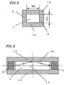
- Figure 2 is a sectional view taken along line a-a ' of a flow path 6 of Figure 1 , viewed from a side thereof.
- the reference numeral 6 denotes the flow path
- 7 denotes a flow measurement section
- 8 and 9 denote side-wall sections of the flow path 6
- 10 and 11 denote ultrasonic oscillators mounted in the side-wall sections 8 and 9 .
- the reference numeral 12 denotes a measurement section connected to the ultrasonic oscillators 10 and 11
- 13 denotes a calculation section connected to the measurement section 12 .
- the reference numeral 14 denotes a lower plate section of the flow path 6
- 15 denotes an upper plate section which is attached to the side-wall sections 8 and 9 .
- the sectional shape of the flow measurement section 7 is a rectangle having a width W0 and a height H0 .
- the side-wall sections 8 and 9 , the lower plate section 14 , and the-upper plate section 15 constituting the flow path 6 are made of a material which is free from a chemical change when in contact with an object fluid.
- an ABS resin was selected as the material.
- the upper plate section 15 is screwed to end surfaces of the side-wall sections 8 and 9 via sealers, to constitute the flow measurement section 7 whose cross section shape is a rectangle.
- the ultrasonic oscillators 10 and 11 are secured to mounts 10a , 11a provided in the side-wall sections 8 , 9 via sealers so that the transmitting and receiving surfaces thereof face each other.
- the operation of the ultrasonic flowmeter having the above configuration will be described.
- the length of a line connecting the centers of the ultrasonic oscillator 10 and the ultrasonic oscillator 11 is denoted by L
- the angle of the above line against the longitudinal direction of the flow measurement section 7 which is the direction of the flow is denoted by ⁇ .
- the acoustic velocity in the air as the object fluid in a windless state is denoted by C
- the flow rate of the air in the flow measurement section 7 is denoted by V .
- An ultrasonic wave transmitted from the ultrasonic oscillator 10 disposed on the upstream side of the flow path 6 obliquely crosses the flow measurement section 7 to be received by the ultrasonic oscillator 11 disposed on the downstream side thereof.
- V L 2 cos ⁇ ⁇ 1 t ⁇ 1 - 1 t ⁇ 2 is obtained. If L and ⁇ are known, the flow rate V is obtained by measuring t1 and t2 by the measurement section 12 .
- Figure 3 is a sectional view taken along line b-b ' of the flow path 6 shown in Figure 1 , viewed from a side thereof.
- the ultrasonic wave received by the ultrasonic oscillator 11 includes a direct wave propagating along a propagation route 17 , for example, in the flow measurement section 7 and a reflected wave propagating along a propagation route 18 , for example, where the wave is reflected once from the inner surface of the upper plate section 15 and is received.
- the propagation routes 17 and 18 represent typical propagation routes. Direct waves which propagate along routes other than the propagation route 17 and reflected waves which propagate along routes other than the propagation route 18 also exist.
- a reflected wave which is reflected from the lower plate section 14 and is propagated or a reflected wave which is received after being reflected, not only once, but twice or more.
- a wave received by the ultrasonic oscillator 11 is observed as a synthetic wave of the direct waves and the reflected waves.
- the propagation distance of the direct wave is different from that of the reflected wave.
- ⁇ 2 ⁇ ⁇ ⁇ ⁇ L ⁇
- the propagation route distribution of direct waves and reflected waves, as well as the respective waveforms, were calculated.
- the shape of the radiation surfaces of the ultrasonic oscillators 10 and 11 is a square (fixed)
- the distance between the ultrasonic oscillators 10 and 11 is L
- the flow measurement section 7 consists of two parallel plates which spread infinitely. It is also assumed that the object fluid does not flow.
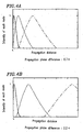
- Figures 4A and 4B show the calculation results of the propagation route distribution of ultrasonic waves which are transmitted by the ultrasonic oscillator 10 and received by the ultrasonic oscillator 11 obtained when the height ( H0 ) is varied so that the propagation phase difference between the propagation routes 17 and 18 is 0.7 ⁇ to 2.2 ⁇ , for example.
- the solid line represents a direct wave
- the dotted line represents a once reflected wave
- the one-dot chain line represents a twice reflected wave.
- the transverse axis of each of Figures 4A and 4B represents the propagation distance for the respective propagation routes
- the longitudinal axis thereof represents the relative intensity of each route.
- the propagation route distribution of the direct wave is wider than that of the direct wave. Moreover, as the propagation phase difference is larger, the distribution tends to be wider. The propagation route distribution of the twice reflected wave is further wider than that of the once reflected wave. Moreover, the distance at which the intensity of each route of the direct wave is maximum is substantially equal to the distance of the propagation route 17 . And, the distance at which the intensity of each route of the once reflected wave is maximum is substantially equal to the distance of the propagation route 18 .
- Figure 5A and 5B illustrate waveforms of received waves calculated by adding pulse response characteristics of the ultrasonic oscillators 10 and 11 to the calculation results of Figures 4A and 4B , respectively.
- the frequency of the ultrasonic oscillators 10 and 11 is assumed to be 270 kHz.
- the solid line represents the direct wave
- the dotted line represents the once reflected wave
- the one-dot chain line represents the twice reflected wave.
- the larger the propagation phase difference is, the smaller the amplitude of the once reflected wave is.
- the twice reflected wave is further smaller than the once reflected wave. This is because, the larger the propagation phase difference between the typical propagation routes 17 and 18 is, the wider the propagation route distribution is and the slower the slope thereof is, as shown in Figures 4A and 4B .
- the propagation phase differences are found over a wide range and are cancelled due to interference of the reflected waves with one another.
- the influence on the direct wave can be reduced by setting the height ( H0 ) so that the propagation route distribution of the reflected wave becomes wide or by setting the height ( H0 ) so that the propagation phase difference between the propagation routes 17 and 18 becomes large.
- the influence of the reflected wave on the direct wave can be further reduced by making the height of the radiation surfaces of the ultrasonic oscillators lower than the height ( H0 ).
- Figures 6 and 7 illustrate the results of experiments performed to confirm the influence of the reflected wave on the direct wave.
- the experiments were performed using the air under the following conditions: the distance between the ultrasonic oscillators 10 and 11 is L ; the effective radiation surfaces of the ultrasonic oscillators 10 and 11 are square; the width is W0 (fixed); and the height ( H0 ) is set so that the propagation phase difference between the propagation routes 17 and 18 is 0.7 n to 2.2 ⁇ .
- the frequency of the ultrasonic oscillators 10 and 11 is 270 kHz.
- the transverse axis of each of Figures 6 and 7 represents the propagation phase difference between the propagation route 17 of the direct wave and the propagation route 18 of the reflected wave, calculated using Expression 5.
- ⁇ denotes the wavelength of the ultrasonic oscillators 10 and 11 obtained under the no-flow condition at room temperature.
- the longitudinal axis of Figure 6 represents the relative received voltage of the received voltage obtained when the ultrasonic oscillators 10 and 11 are disposed in the flow path 6 with respect to the received voltage when they are disposed in an open space. The measurement was performed under no flow.
- the longitudinal axis of Figure 7 represents the variation of the received voltage obtained under a flow of about 6,000 liters/hour with respect to the received voltage obtained under no flow.
- the received voltage obtained under no flow tends to be lowest when the propagation phase difference is in the range of about n to 1.4 n. It is observed from the variation of the received voltage due to the flow shown in Figure 7 that the received voltage is lowest when the propagation phase difference is in the range of about 0.8 n to 1.2 ⁇ for the combination of the ultrasonic oscillator 10 as the transmitter and the ultrasonic oscillator 11 as the receiver. In reverse, the received voltage is highest in the above range for the combination of the ultrasonic oscillator 11 as the transmitter and the ultrasonic oscillator 10 as the receiver. A phenomenon of such an increase in the received voltage will not occur if no phase influence exists in the superimposition between the direct wave and the reflected wave.
- the received voltage tends to be reduced when the propagation phase difference is 3n/2 or more, for both the combination of the ultrasonic oscillator 10 as the transmitter and the ultrasonic oscillator 11 as the receiver and the combination of the ultrasonic oscillator 11 as the transmitter and the ultrasonic oscillator 10 as the receiver. This is presumably because the directivity of each of the ultrasonic oscillators 10 and 11 has been deflected due to the flow.
- the propagation phase difference between the direct wave and the reflected wave influences the measurement results
- the influence of the reflected wave can be reduced with a simple structure, allowing the flow of an object fluid to be measured with high precision over a wide range in a short time so that the propagation phase difference between the propagation route 17 and the propagation route 18 is 3/2 ⁇ or more.
- no concave or convex portion is formed in the flow measurement section 7 , neither a disturbance of the flow nor an increase in pressure loss will occur.
- Example 1 the height ( H0 ) at which the propagation phase difference between the propagation routes 17 and 18 is in the range of 0.7 n to 2.2 n was selected. Alternatively, a height ( H0 ) at which the propagation phase difference between the propagation routes 17 and 18 is in the range of 2.2 n or more may be selected. Otherwise, the distance ( L ) between the ultrasonic oscillators 10 and 11 or the frequency thereof may be selected.
- Example 2 according to the present invention will be described with reference to Figures 8 and 9 .
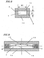
- Figure 8 is a cross sectional view taken along line a-a ' of the flow path 6 of an ultrasonic flowmeter of Example 2 according to the present invention, viewed from a side thereof.
- Figure 9 is a sectional view taken along line b-b ' of the flow path 6 , viewed from a side thereof.
- the reference numerals 8 , 9 , 14 , and 15 denote the side-wall sections, the lower plate section, and the upper plate section, which are substantially the same configuration of Figure 2 .
- the reference numerals 10 and 11 denote the ultrasonic oscillators, which are substantially the same configuration of Figure 3 .
- the method for making the flow path of the ultrasonic flowmeter having the above configuration and the operation principle thereof are substantially the same as those of Example 1 and thus omitted here.
- the cross section area of the flow measurement section 7 is made substantially the same as the inner diameter of a pipe for supplying an object fluid, and in some cases it is desired to increase the aspect ratio of the height ( H1 ) to the width ( W1 ) (W1/H1) in view of the flow rate distribution. In such cases, it is sometimes impossible to selectively combine the distance ( L ) between the ultrasonic oscillators 10 and 11 , the height ( H1 ), and the frequency so that the propagation phase difference between a propagation route 19 and a propagation route 20 is 3n/2 or more. Then, a means for reducing the influence of the reflected wave while increasing the aspect ratio is considered.
- Figures 10 and 11 illustrate the results of experiments performed to confirm the influence of the reflected wave on the direct wave.
- the experiments were performed using the air under the following conditions: the distance between the ultrasonic oscillators 10 and 11 is L ; the effective radiation surfaces of the ultrasonic oscillators 10 and 11 are square; the width is W1 (fixed); and the height ( H1 ) is set so that the propagation phase difference between the propagation routes 19 and 20 is in the range of 0.05 n to 0.7 n.
- the frequency of the ultrasonic oscillators 10 and 11 is 270 kHz.
- the transverse axes of Figures 10 and 11 represent the propagation phase difference between the propagation route 19 of the direct wave and the propagation route 20 of the reflected wave, calculated from Expression 5.
- ⁇ denotes the wavelength of the ultrasonic oscillators 10 and 11 obtained under no-flow at room temperature.
- the longitudinal axis of Figure 10 represents the relative received voltage of the received voltage measured when the ultrasonic oscillators 10 and 11 are disposed in the flow path 6 with respect to the received voltage thereof measured when they are disposed in an open space. The measurement was performed under no flow.
- the longitudinal axis of Figure 11 represents the variation of the received voltage obtained under a flow of about 6,000 liters/hour with respect to the received voltage obtained under no flow.
- the received voltage is smaller as the propagation phase difference is smaller. This is presumably because, since the effective radiation surfaces of the ultrasonic oscillators 10 and 11 were fixed while the height ( H1 ) was reduced, portions of the ultrasonic oscillators 10 and 11 were blocked by the lower plate section 14 and the upper plate section 15.
- the variation has a difference between the combination of the ultrasonic oscillator 10 as the transmitter and the ultrasonic oscillator 11 as the receiver and the combination of the ultrasonic oscillator 11 as the transmitter and the ultrasonic oscillator 10 as the receiver.
- the variations are substantially equal between the combination of the ultrasonic oscillator 10 as the transmitter and the ultrasonic oscillator 11 as the receiver and the combination of the ultrasonic oscillator 11 as the transmitter and the ultrasonic oscillator 10 as the receiver.
- the influence of the reflected wave can be reduced to realize high-precision flow measurement over a wide range if the frequency of the ultrasonic oscillators 10 and 11 , the distance ( L ) between the ultrasonic oscillators 10 and 11 , and the height ( H1 ) are appropriately combined so that the propagation phase difference between the propagation routes 19 and 20 is about 0.2 n or less.
- Higher-precision flow measurement is possible if the distance ( L ) and the height ( H1 ) are fixed. This is, because as the frequency of the ultrasonic oscillators 10 and 11 is set lower the propagation phase difference can be made smaller.
- Example 2 the height ( H1 ) at which the propagation phase difference between the propagation routes 19 and 20 is in the range of 0.05 n to 0.7 ⁇ was selected. Alternatively, a height ( H1 ) at which the propagation phase difference between the propagation routes 19 and 20 is 0.05 n or less may be selected. Otherwise, the distance ( L ) between the ultrasonic oscillators 10 and 11 or the frequency thereof may be selected.
- Figure 12 is a sectional view taken along line a-a ' of the flow path 6 of an ultrasonic flowmeter in Example 3 according to the present invention, viewed from a side thereof.
- the reference numerals 8 , 9 , 14 , and 15 denote the side-wall sections, the lower plate section, and the upper plate section of the flow path 6 , which are substantially the same configuration of Figure 2 .
- the different point from the configuration of Figure 2 is that the cross section of the flow measurement section is divided by partition plates 21a and 21b into three portions to form divided flow measurement portions 22a to 22c .
- the partition plates 21a and 21b made of SUS having a thickness of 0.2 mm are secured to the side-wall sections 8 and 9 with an adhesive so as to be parallel with the inner surface of the lower plate section 14 .
- the upper plate section 15 is screwed to the end surfaces of the side-wall sections 8 , 9 via sealants.
- Respective heights ( H2a , H2b , H2c ) are set so that the aspect ratio of the divided flow measurement portions ( 22a , 22c ) is about 20 and the aspect ratio of the divided flow measurement portion ( 22b ) is about 17.
- the distance ( L ) between the ultrasonic oscillators 10 , 11 is selected so that a propagation phase difference of about 0.04 n is generated between a propagation route 23 and a propagation route 24 in the divided flow measurement portion ( 22b ), and that a propagation phase difference of about 0.1 ⁇ is generated between a propagation route 25 and a propagation route 26 in the divided flow measurement portion ( 22a ). It is assumed that the effective radiation surfaces of the ultrasonic oscillators 10 , 11 are square and that the frequency thereof is 270 kHz.
- the method for mounting the ultrasonic oscillators in the ultrasonic flowmeter having the above configuration, as well as the operation principle thereof, are substantially the same as those of Example 1, and thus omitted here.
- Figure 13 is a sectional view taken along line b-b ' of the flow path 6 , viewed from a side thereof.
- a direct wave propagates along a route such as the propagation route 23
- a reflected wave propagates along a route such as the propagation route 24 where they are reflected from the partition plate 21b
- a direct wave propagates along a route such as the propagation route 25
- a reflected wave propagates along a route such as the propagation route 26 where they are reflected from the upper plate section 15 . Since the height ( H2c ) of the flow measurement portion 22c is set to be equal to the height ( H2a ) of the divided flow measurement portion 22a, the relationship between direct waves and reflected waves is substantially the same as that in the divided flow measurement portion 22a .
- the ultrasonic oscillator 11 observes a synthetic wave of all the direct waves and reflected waves propagating inside the divided flow paths ( H2a , H2b , H2c ) as a received wave.
- the heights of the divided flow measurement portions ( 22a to 22c ) are set so that the propagation phase difference between the direct wave and the reflected wave is 0.2 ⁇ or less. Accordingly, the phase relationships in the superimposition of the direct waves and the reflected waves are not influenced by the flow, thereby reducing the influence of the reflected wave on direct wave.
- the influence of the reflected wave can be reduced by dividing the flow measurement section into a plurality of portions using a partition plate. Moreover, the stabilization of the flow can be achieved, allowing the flow of an object fluid to be measured with high precision in a short time.
- Example 3 although the flow measurement section was divided into three portions, the flow measurement section may be divided into two, four or more portions as long as the phase difference between the direct wave and the reflected wave can be reduced.
- the values of the heights ( H2a to H2c ) may be changed appropriately.
- ultrasonic waves are assumed to propagate in all the divided flow measurement portions. However, the ultrasonic waves do not have to propagate in all the divided measurement portions as long as the precision of the flow measurement is satisfactory.
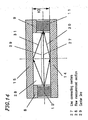
- Figure 14 is a sectional view taken along line b-b ' of the flow path 6 of an ultrasonic flowmeter of Example 4 according to the present invention, viewed from a side thereof.
- the reference numerals 8 , 9 , 14 , 15 denote the side-wall sections, the lower plate section, and the upper plate section of the flow path 6 , which are substantially the same configuration of Figure 3 .
- the difference from the configuration of Figure 3 is that the ultrasonic oscillators 10 , 11 are disposed in the side-wall sections 8 and 9 so that a line 27 connecting the centers of the ultrasonic oscillators 10 , 11 and a center line 29 of a height ( H3 ) are parallel with each other but do not match with each other.
- the line 27 connecting the centers of the pair of ultrasonic oscillators is shifted in parallel from the center line 29 of the height ( H3 ) of a flow measurement section 28 , so that the reflected wave from the inner surface of the lower plate section 14 and the reflected wave from the upper plate section 15 reach the ultrasonic oscillator at different phases, respectively.
- the ultrasonic oscillators 10 , 11 are screwed to the side-wall sections 8 , 9 via sealants so that the propagation phase difference between a propagation route 27 of a direct wave and a propagation route 30 of a reflected wave reflected from the lower plate section 14 is 0.7 ⁇ and the propagation phase difference between the propagation route 27 and a propagation route 31 of a reflected wave reflected from the upper plate section 15 is 2.2 ⁇ .
- the upper plate section 15 is screwed to the end surfaces of the side-wall sections 8 , 9 via sealants.
- the distance between the ultrasonic oscillators 10 , 11 , the shape of the effective radiation surfaces thereof, the frequency thereof, and the object fluid are the same as those in Example 1.
- the operation principle of the ultrasonic flowmeter having the above configuration is substantially the same as that in Example 1, and thus omitted here.
- a direct wave propagates along the line 27 connecting the centers of the ultrasonic oscillators.
- Reflected waves have the propagation route 30 reflected from the inner surface of the lower plate section 14 and the propagation route 31 reflected from the inner surface of the upper plate section 15. Such reflected waves are received at around the center of the ultrasonic oscillator 11 .
- the illustrated propagation routes of the directed wave and the reflected waves are typical propagation routes. As in Example 1, there exist other propagation routes not shown. If the line 27 connecting the centers and the center line 29 match with each other, the propagation distances of the propagation route 30 and the propagation route 31 are equal to each other, generating no propagation phase difference.
- the propagation phase difference of the reflected wave reflected from the lower plate section can be made different from that of the reflected wave reflected from the upper plate section by disposing the ultrasonic, oscillators so that the line connecting the centers thereof is shifted in parallel from the center line of the height ( H3 ) of the flow measurement section. This enables to reduce the influence of the reflected wave on the direct wave and thus measure the flow of an object fluid with high precision in a short time.
- Example 4 the line 27 connecting the centers of the ultrasonic oscillators was shifted in parallel from the center line 29 of the height ( H3 ) of the flow measurement section so that the propagation phase difference between the propagation route 27 of the direct wave and the propagation route 30 of the reflected wave reflected from the lower plate section 14 is 0.7 n and the propagation phase difference between the propagation route 27 and the propagation route 31 of the reflected wave reflected from the upper plate section 15 is 2.2 n.
- the present invention is not limited to the above conditions, but the conditions can be appropriately changed.
- Example 5 according to the present invention will be described with reference to the relevant drawing.
- Figure 15 is a sectional view taken along line b- b' of the flow path 6 of an ultrasonic flowmeter of Example 5 according to the present invention, viewed from a side thereof.
- the reference numerals 8 , 9 , 14 , 15 denote the side-wall sections, the lower plate section, and the upper plate section of the flow path 6 , which are substantially the same configuration of Figure 3 .
- the difference from the configuration of Figure 3 is that the ultrasonic oscillators 10 , 11 are disposed in an inclined state so that a line 32 connecting the centers of the ultrasonic oscillators 10 , 11 and a center line 33 of a height ( H4 ) of a flow measurement section 36 cross at a predetermined angle ( ⁇ 4 ).
- Example 4 in order to obtain a high-precision flowmeter, reducing the influence of the reflected wave is required. To achieve this, it is considered to generate a propagation phase difference between the reflected wave from the inner surface of the lower plate section 14 and the reflected wave from the upper plate section 15 .
- One of methods for generating the propagation phase difference selected by this example is disposing the ultrasonic oscillators 10 , 11 so that the line 32 connecting the centers of the ultrasonic oscillators 10 , 11 and the center line 33 of the height ( H4 ) cross at the predetermined angle ( ⁇ 4 ).
- the ultrasonic oscillators 10 , 11 are screwed to the side-wall sections 8 , 9 via sealants so that the line 32 connecting the centers of the ultrasonic oscillators 10, 11 is inclined by about 2.5 degrees with respect to the center line 33 of the height ( H4 ).
- the upper plate section 15 is then screwed to the end surfaces of the side-wall sections 8 , 9 via sealants.
- the distance between the ultrasonic oscillators 10 , 11 , the shape of the effective radiation surfaces thereof, the frequency thereof, and the object fluid are the same as those in Example 1.
- the operation principle of the ultrasonic flowmeter having the above configuration is substantially the same as that described in Example 1, and thus omitted here.
- a direct wave propagates along the line 32 connecting the centers, for example.
- a propagation route 34 and a propagation route 35 extend from around the center of the ultrasonic oscillator 10 in directions toward the lower plate section 14 and the upper plate section 15 , respectively, crossing the same angle.
- the illustrated propagation routes of the directed wave and the reflected waves are typical propagation routes.
- An ultrasonic wave propagating along the propagating route 34 is reflected from the lower plate section 14
- an ultrasonic wave propagating along the propagating route 35 is reflected from the upper plate section 15 .
- the reflected waves propagating along the propagation route 34 and the propagation route 35 generates a propagation phase difference since they have different propagation distances.
- the ultrasonic oscillator 11 receives both the reflected waves at the same position thereof.
- the ultrasonic oscillator 11 receives the reflected waves at different positions. Accordingly, these reflected waves interfere and influence with each other, resulting in reducing the influence of the reflected waves on the direct wave.
- Example 5 the line 32 connecting the centers of the ultrasonic oscillators 10 , 11 is inclined by about 2.5 degrees against the center line 33 of the height ( H4 ).
- the present invention is not limited to the above condition, but the inclination angle may be larger or smaller than 2.5 degrees.
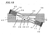
- Figure 16 is a top view of a flow path of an ultrasonic flowmeter of Example 6 according to the present invention.
- Figure 17 is a sectional view taken along line c-c' of the flow path in Figure 16 , viewed from a side thereof.
- Figure 18 is a sectional view taken along line d-d ' of the flow path in Figure 16 , viewed from a side thereof.
- the reference numeral 37 denotes a flow path
- 38 denotes an upper plate section of the flow path 37
- 39 denotes a mount a for the ultrasonic oscillator 10 provided on the upper plate section 38
- 40 denotes a lower plate section of the flow path 37
- 41 denotes a mount b for the ultrasonic oscillator 11 provided on the lower plate section 40
- 42 and 43 denote side-wall sections of the flow path 37
- 44 denotes a flow measurement section.
- the upper plate section 38 , the lower plate section 40 , the mounts 39 , 41 , and the side-wall sections 42 , 43 constituting the flow path 37 are made of a material which is free from a chemical change against an object fluid.
- an ABS resin was selected as the material.
- the mount 39 is adhered to the upper plate section 38 so that the angle ( ⁇ 5) crossing the direction of the longitudinal axis of the upper plate section 38 and a direction d-d ' of the mounting of the ultrasonic oscillator 10 is 30 degrees, for example.
- the mount 41 is adhered to the lower plate section 40 so that the angle ( ⁇ 5) crossing the direction of the longitudinal axis of the lower plate section 40 and the direction d-d ' of the mounting of the ultrasonic oscillator 11 is 30 degrees.
- the upper plate section 38 is screwed to the end surfaces of the side-wall sections 42 , 43 via sealers, to constitute the flow measurement section 44 whose cross section shape is a rectangle.
- the ultrasonic oscillators 10 , 11 are then secured to the mounts 39 , 41 via sealers 45 , 46 so that the angle ( ⁇ 6 ) crossing a line 47 connecting the centers of the ultrasonic oscillators 10 , 11 and a center line of the height ( H5 ) of the d-d ' cross section is 30 degrees.
- the distance between the ultrasonic oscillators 10 , 11 , the shape of the effective radiation surfaces thereof, and the frequency thereof are substantially the same as those in Example 1.
- the operation principle of the ultrasonic flowmeter having the above configuration is substantially the same as that described in Example 1, and thus omitted here.
- the propagation of an ultrasonic wave in the flow measurement section 44 will be described using exemplary propagation routes 47 to 49 shown in Figure 18 .
- the propagation routes 47 to 49 are typical propagation routes. There exist other propagation routes not shown.
- a direct wave transmitted from the ultrasonic oscillator 10 propagates along the propagation route 47 toward the ultrasonic oscillator 11 .
- the ultrasonic waves transmitted from the ultrasonic oscillator 10 propagate, they generally spread, and thus, some of them propagate along the propagation routes 48 and 49 .
- an ultrasonic wave which propagates along the propagation route 48 and is reflected from the lower plate section 40 will never reach the ultrasonic oscillator 11 after being reflected again from the wall of the flow measurement section 44 .
- an ultrasonic wave which propagates along the propagation route 49 and is reflected from the side-wall section 42 will never reach the ultrasonic oscillator 11 after being reflected again from the wall of the flow measurement section 44 .
- the ultrasonic oscillators 10 , 11 disposed in the above positional relationship no reflected wave which is reflected only once from the flow measurement section 44 is received by the ultrasonic oscillator 11 . Therefore, reflected waves which influence on direct waves have been reflected twice or more. A reflected wave which was reflected twice or more influences on a direct wave considerably less than a reflected wave which was reflected only once. This allows to reduce the influence of the reflected wave.
- Example 6 although the angle ( ⁇ 5 ) crossing the direction of the longitudinal axis of the flow path 37 and the direction d-d ' of the mounting of the ultrasonic oscillators was set at 30 degrees, and the angle ( ⁇ 6 ) crossing the line 47 connecting the pair of ultrasonic oscillators and the center line of the height ( H5 ) was set at 30 degrees, the present invention is not limited to the above conditions, but an appropriate angle can be used.
- Figure 19 is a sectional view taken along line a-a ' of the flow path 6 of an ultrasonic flowmeter of Example 7, viewed from a side thereof.
- the reference numerals 8 , 9 , 14 , 15 denote the side-wall sections, the lower plate section, and the upper plate section of the flow path 6, which are substantially the same configuration of Figure 2 .
- the difference from the configuration of Figure 2 is that structures 50 , 51 having a size which does not divide a flow measurement section 52 into layers are attached to the side-wall sections 8, 9.
- the method is considered to provide a reflection plate in the flow measurement section 52 so that the propagation phase difference between the direct wave and the reflected wave can be set at a desired value.
- the upper plate section 15 is screwed to the end surfaces of the side-wall sections 8 and 9 via sealers.
- the distance between the ultrasonic oscillators 10 , 11 , the shape of the effective radiation surfaces thereof, the frequency thereof, and the object fluid are the same as those in Example 1.
- the method for mounting the ultrasonic oscillators to the ultrasonic flowmeter having the above configuration, as well as the operation principle of the ultrasonic flowmeter, are substantially the same as those described in Example 1, and thus omitted here.
- the propagation of an ultrasonic wave in the flow measurement section 52 will be described using exemplary propagation routes 53 and 54 shown in Figure 20 .
- the propagation routes 53 and 54 are typical propagation routes. There exist other propagation routes not shown as well as Example 1.
- Figure 20 is a sectional view taken along line b-b' of the flow path 6 , viewed from a side thereof.
- a direct wave propagates along the propagation route 53 .
- a reflected wave propagates along the propagation route 54 , for example, where it is repeatedly reflected from the structure 50a and then from the lower plate section 14 .
- the reflected wave propagating along the propagation route 54 has a longer propagation distance than a reflected wave which is reflected only once from the upper plate section 15 .
- the propagation phase difference between the direct wave and the reflected wave can be set at a desired value by providing the structures. This allows to reduce the influence of the reflected wave and perform a high-precision measurement of the flow of an object fluid in a short time.
- Example 7 the structures made of SUS having a thickness of 0.2 mm and a length ( L6 ) of 7 mm were used.
- the present invention is not limited to the above conditions, but appropriate size and material can be used.
- the structures 50 , 51 were adhered to the side-wall sections 8 , 9 .
- the structures may be disposed at positions other than the side-wall sections 8 , 9 .
- a total of four structures were used.
- any number of structures, which is one or more, may be used.
- Figure 21 is a sectional view taken along line a-a ' of the flow path 6 of an ultrasonic flowmeter of Example 8, viewed from a side thereof.
- the reference numerals 8 , 9 , 14 , 15 denote the side-wall sections, the lower plate section, and the upper plate section of the flow path 6 , which are substantially the same configuration of Figure 2 .
- the difference from the configuration of Figure 2 is that structures 55a , 55b which do not divide a flow measurement section 56 into layers are disposed on the lower plate section 14 and the upper plate section 15 .
- the method is considered to provide a reflection plate in the flow measurement section 56 so that the reflected wave is less easily received.
- Structures 55a , 55b made of SUS having a thickness of 0.2 mm and a length ( L7 ) of 1 mm are secured with an adhesive around the center of the width ( W7 ) so as to be perpendicular to the inner surfaces of the lower plate section 14 and the upper plate section 15 .
- the upper plate section 15 is screwed to the end surfaces of the side-wall sections 8 and 9 via sealers.
- the distance between the ultrasonic oscillators 10 , 11 , the shape of the effective radiation surfaces thereof, the frequency thereof, and the object fluid are the same as those in Example 1.
- the method for mounting the ultrasonic oscillators in the ultrasonic flowmeter having the above configuration and the operation principle of the ultrasonic flowmeter are substantially the same as those described in Example 1, and thus omitted here.
- FIG. 22 is a sectional view taken along line b-b ' of the flow path 6 , viewed from a side thereof.
- An ultrasonic wave transmitted from the ultrasonic oscillator 10 propagates and spreads. For example, a direct wave propagates along the propagation route 57 .
- a spread ultrasonic wave is reflected from the upper plate section 15 and the lower plate section 14 , to be received by the ultrasonic oscillator 11 as a reflected wave.
- the propagation of a reflected wave propagating along the propagation route 58 is blocked by the structure 55a . Therefore, the reflected wave propagating along the propagation route 58 is not received by the ultrasonic oscillator 11 .
- propagation routes other than the propagation route 58 exist for reflected waves, some propagations of the reflected waves can be blocked by the structures 55a , 55b . This allows to reduce the influence of the reflected wave on the direct wave.
- the influence of the reflected waves can be reduced by appropriately selecting the positions and the number of structures provided. This allows to perform a high-precision measurement of the flow of an object fluid in a short time.
- Example 8 although the structures 55a , 55b made of SUS having a thickness of 0.2 mm and a length ( L7 ) of 1 mm were disposed around the center of the width ( W7 ), the present invention is not limited to the above conditions, but appropriate size, position, and material can be used.
- the structures 55a , 55b were adhered to the lower plate section 10 and the upper plate section 15 .
- the structures may be disposed at positions other than the lower plate section and the upper plate section.
- two structures were provided.
- any number of structures, which is one or more, may be used.
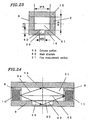
- Figure 23 is a sectional view taken along line a-a ' of the flow path 6 of an ultrasonic flowmeter of Example 9, viewed from a side thereof.
- the reference numerals 8 , 9 , 14 , 15 denote the side-wall sections, the lower plate section, and the upper plate section of the flow path 6 , which are substantially the same configuration of Figure 2 .
- the difference from the configuration of Figure 2 is that a concave portion 59 is formed in the lower plate section 14 , and is covered by a mesh structure 60.
- the method is considered to form a concave portion in the flow measurement section 61 and a mesh structure covering the concave portion so that the flow is not disturbed by the concave portion.
- the concave portion 59 is formed using a fraise around the center of the lower plate section 14 of the flow measurement section 61 of which aspect ratio (W8/H8) is 5, for example, so that the propagation phase difference between a propagation route 62 and a propagation route 63 is 2.2 ⁇ .
- a mesh structure which covers the concave portion 59 is secured to prevent the air as the object fluid from flowing thereinto.
- the mesh structure should have a mesh size of No. 100, for example, to allow an ultrasonic wave to pass therethrough.
- the upper plate section 15 is screwed to the end surfaces of the side-wall sections 8 , 9 via sealers so that the propagation phase difference between the propagation route 62 and a propagation route 64 is 1.2 n.
- the distance between the ultrasonic oscillators 10 , 11 , the shape of the effective radiation surfaces thereof, the frequency thereof, and the object fluid are the same as those in Example 1.
- the method for mounting the ultrasonic oscillators in the ultrasonic flowmeter having the above configuration and the operation principle of the ultrasonic flowmeter, are substantially the same as that described in Example 1, and thus omitted here.
- Figure 24 is a sectional view taken along line b-b' of the flow path 6 , viewed from a side thereof.
- a direct wave propagates along the propagation route 62 .
- a reflected wave reflected from the lower plate section 14 propagates along the propagation route 63 , for example, where it is reflected from the bottom of the concave portion 59 .
- a reflected wave reflected from the upper plate section 15 propagates along the propagation route 64 , for example.
- the propagation routes 62 to 64 are typical propagation routes, there exist other propagation routes not shown, as well as Example 1. Some reflected waves are reflected from the surface of the mesh structure 60 without passing through the mesh structure 60 .
- the propagation route distributions of these reflected waves are different. These result in that the reflected waves reflected from the lower plate section 14 and the upper plate section 15 interfere and influence each other. In this way, by forming an asymmetric configuration of the lower plate section 14 and the upper plate section 15 , the influence of the reflected wave on the direct wave can be reduced. Since the mesh structure 60 covers the concave portion 59, the air flows through the flow measurement section 61 without flowing into the concave portion 59 . Therefore, the flow is not disturbed. Alternatively, the ultrasonic waves may propagate in the flow measurement section 61 including the concave portion 59 .
- the propagation phase difference between the direct wave and the reflected wave can be set at a desired value by forming the structure, and a stable flow distribution is attained in the range of a measured flow. This enables to reduce the influence of the reflected wave and measure the flow of an object fluid with high precision in a short time.
- the concave portion 59 was formed so that the propagation phase difference between the propagation route 62 and the propagation route 63 is 2.2 ⁇ .
- the present invention is not limited to the above condition, but an appropriate value can be used.
- the mesh structure 60 of a mesh size of No. 100 or the like was formed covering the concave portion 59 .
- Other mesh structures may also be used.
- no mesh structure is required unless the concave portion 59 influences the flow to such a degree that will cause a problem at measurement.
- the concave portion 59 was formed at around the center of the lower plate section 14 . Any number of such concave portions may be formed at any positions as long as the reduction of the influence of the reflected wave is achieved.
- the concave portion may be formed on the upper plate section 15 , or a convex portion may be formed in addition to the concave portion 59 .
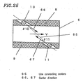
- Example 10 according to the present invention will be described with reference to the relevant drawing.
- Figure 25 is a sectional view of the flow path 6 of an ultrasonic flowmeter of Example 10, viewed from the top thereof.
- the reference numeral 6 denotes the flow path
- 8 and 9 denote the side-wall sections of the flow path 6 , which are substantially the same configuration of Figure 1 .
- the difference from the configuration of Figure 1 is that a center direction 66 of the ultrasonic oscillator 10 is shifted by an angle ⁇ 10 (about 5 degrees) upstream against a line 65 connecting the centers of the ultrasonic oscillators 10 and 11 , and a center direction 67 of the ultrasonic oscillator 11 is shifted by an angle ⁇ 11 (about 5 degrees) downstream against the line 65 .
- the method for making the flow path, the method for mounting the ultrasonic oscillators, and the operation principle are substantially the same as those of Example 1, and thus the descriptions thereof are omitted here.
- the distance between the ultrasonic oscillators 10 , 11 , the shape of the effective radiation surfaces thereof, the frequency thereof, and the object fluid are the same as those in Example 1.
- an ultrasonic oscillator tends to have a strong directivity toward the center direction thereof. Therefore, in an open space, the greatest received voltage is obtained when the ultrasonic oscillators 10 , 11 are disposed to face each other to match the directivities thereof.
- the ultrasonic oscillators 10 , 11 are disposed so that the center directions 66 , 67 thereof are shifted by the angles ⁇ 10 , ⁇ 11 against the line 65 connecting the centers thereof. Under this configuration, although the received voltage of the direct wave decreases, the reflected wave has a comparatively weak directivity, and the received voltage of the reflected waves are reduced. Thus, the influence of the reflected wave can be reduced.
- the ultrasonic oscillators by disposing the ultrasonic oscillators so that the center lines thereof are shifted from the line connecting the centers thereof, the influence of the reflected wave on the direct wave can be reduced, and the flow of an object fluid can be measured with high precision in a short time.
- Example 10 the center lines 66 , 67 were shifted by five degrees against the line 65 connecting the centers of the ultrasonic oscillators.
- the present invention is not limited to the above condition, but an appropriate angle can be used.
- the center lines of the ultrasonic oscillators 10 , 11 were shifted upstream and downstream. Alternatively, they may be shifted toward the lower plate section and the upper plate section. Moreover, a combination of any directions may be used.
- Example 11 according to the present invention will be described with reference to the relevant drawing.
- Figure 26 is a local sectional view illustrating the mounting of an ultrasonic flowmeter of Example 11 according to the present invention in piping.
- the reference numerals 10a , 11a denote mounts
- 14 , 15 denote the lower plate section and the upper plate section of the flow path 6
- 68 denotes a rectifying means
- 69 denotes the flow measurement section
- 70 , 71 denote pipes.
- the configuration of the flow measurement section 69 not shown in this figure is substantially the same as that of any of Examples 1 to 10.
- the difference from any configuration of Examples 1 to 10 is that the rectifying means 68 is provided in the flow measurement section 69 .
- the rectifying means 68 is composed of an aluminum honeycomb structure and secured to the lower plate section 14 , the upper plate section 15 , and the side-wall section (not shown) with an adhesive so as not to be moved due to the air flow.
- the method for making the flow path of the ultrasonic flowmeter, the method for mounting the ultrasonic oscillators, and the operation principle are substantially the same as those in Example 1, and thus omitted here.
- a straight pipe portion which is sufficiently long compared with the diameter of the pipe (about ten times) is formed on the upstream side of the flow measurement section in order to stabilize the distribution of the flow rate and the direction of the flow. Due to the downsizing of the ultrasonic flowmeter and the restriction of the mounting site thereof, it is difficult to provide a straight pipe portion which is sufficiently long compared with the diameter of the pipe on the upstream side of the flow measurement section 69 . Moreover, in some cases, the pipe 70 is arranged perpendicular to the flow path 6 . Under this configuration, the air flows in the flow measurement section 69 while the flow direction thereof is being disturbed, and these result in influencing the measurement precision.
- the rectifying means 68 having a honeycomb structure is provided to stabilize the air flow when it flows from the pipe 70 into the flow measurement section 69 .
- the flow direction of the air which has passed through the rectifying means 68 is made uniform to be substantially parallel to the lower plate section 14 and the upper plate section 15 .
- the flow direction can be stabilized by providing the rectifying means 68 on the upstream side of the flow measurement section 69 .
- the rectifying means By combining the rectifying means with the means of reducing the influence of the reflected wave described in any of Examples 1 to 10, the flow of an object fluid can be measured with high precision in a short time.
- Example 11 the honeycomb structure made of aluminum was used as the rectifying means 68 .
- a pipe, a mesh structure, or a plate may also be used as long as the rectifying effect is obtained.
- a metal such as SUS, a resin, or a composite material may be used as the material.
- the pipes 70 , 71 were mounted perpendicular to the upper plate section 15 . Alternatively, they may be mounted on a section other than the upper plate section 15 , or they may be mounted horizontally on the section.
- the rectifying means 68 was provided on the upstream side. Alternatively, rectifying means may be provided on both the downstream side and the upstream side.
- the height ( H0, H1, H2, H6 ) is illustrated as being equal to the height of the ultrasonic oscillators 10, 11 , the height of the ultrasonic oscillators 10 , 11 may be smaller or larger than the height ( HO , H1 , H2 , H6 ).
- the ultrasonic oscillators 10 , 11 were disposed in the side-wall sections 8 , 9 with an inclined state against the flow. Alternatively, they may be disposed at positions other than the side-wall sections 8 , 9 , or they may be disposed parallel to the flow, as long as the measurement of the flow is possible.
- the section of the flow measurement section was a rectangle. The section may be a circle or an oval if the ultrasonic oscillators 10 , 11 are disposed parallel to the flow.
- the effective radiation surfaces of the ultrasonic oscillators 10 , 11 were a square.
- the present invention is not limited to the above condition, but a circle, an oval, or any polygon may be used.
- the frequency of the ultrasonic oscillators 10 , 11 was 270 kHz.
- the present invention is not limited to this, but a frequency higher than or lower than 270 kHz can be used.
- the section of the flow measurement section was a rectangle.
- the present invention is not limited to this shape, but a shape obtained by deforming a portion of a rectangle, or a polygon other than a rectangle may also be used.
- the object fluid was the air.
- a gas other than the air such as an LP gas and a town gas, or a liquid such as water may be used.
- an ABS resin was used as the material of the flow path 6 .
- any material can be used as long as it is free from a chemical change against the object fluid.
- the object fluid is an LP gas, a city gas, or the like, a metal such as SUS and die-cast aluminum may be used.
- the sectional area of the flow measurement section was substantially the same as the inner diameter of a pipe for supplying an object fluid in order to reduce the pressure loss. Alternatively, the sectional area may be larger or smaller as required.
- the ultrasonic flowmeter according to the present invention may be used as an ultrasonic gas meter such as a household gas meter and as a current meter for measuring the flow rate of an object fluid. It is needless to say that the present invention may be configured in combination of any of the above examples.
- the first ultrasonic flowmeter includes: a pair of ultrasonic oscillators; a measurement section for measuring a time in which an ultrasonic wave propagates between the pair of ultrasonic oscillators; and a calculation section for calculating the flow of the fluid flowing in a flow measurement section based on an output from the measurement section, wherein the flow measurement section and the pair of ultrasonic oscillators are configured so that an influence of a reflected wave reflected from a wall of the flow measurement section on a measurement result is reduced. Accordingly, the influence of the reflected wave in the flow measurement section can be reduced, to obtain a high-precision ultrasonic flowmeter.
- the second ultrasonic flowmeter for measuring a flow of a fluid by use of ultrasonic wave, includes: a pair of ultrasonic oscillators; a measurement section for measuring a time in which an ultrasonic wave propagates between the pair of ultrasonic oscillators; and a calculation section for calculating the flow of the fluid flowing in a flow measurement section based on an output from the measurement section, wherein, in a configuration where a phase difference between a direct wave which propagates in the fluid flowing in the flow measurement section without being reflected from a wall of the flow measurement section and a reflected wave which is reflected from a wall of the flow measurement section influences a measurement result, the flow measurement section and the pair of ultrasonic oscillators are configured so that an influence of the phase difference between the direct wave and the reflected wave on the measurement result can be reduced. Accordingly, the influence of the reflected wave in the flow measurement section can be reduced, to obtain a high-precision ultrasonic flowmeter.
- the third ultrasonic flowmeter for measuring a flow of a fluid by use of ultrasonic wave, includes: a pair of ultrasonic oscillators; a measurement section for measuring a time in which an ultrasonic wave propagates between the pair of ultrasonic oscillators; and a calculation section for calculating the flow of the fluid flowing in a flow measurement section based on an output from the measurement section, wherein, in a configuration where a phase difference between a direct wave which propagates in the fluid flowing in the flow measurement section without being reflected from a wall of the flow measurement section and a reflected wave which is reflected from a wall of the flow measurement section influences a measurement result, parameters relating to a frequency of the pair of ultrasonic oscillators, a distance between the pair of ultrasonic oscillators, and a sectional shape of the flow measurement section are combined so that an influence of the phase difference between the direct wave and the reflected wave on the measurement result can be reduced. Accordingly, the influence of the reflected wave in the flow measurement section can be reduced with a
- the direct wave is a wave which propagates along a straight line connecting centers of the pair of ultrasonic oscillators
- the reflected wave is a wave which propagates along two equal sides of an isosceles triangle formed by connecting the centers of the pair of ultrasonic oscillators and a point on a wall of the flow measurement section
- a propagation phase difference caused by a difference between a propagation distance of the direct wave and a propagation distance of the reflected wave is 3 ⁇ /2 or more. Accordingly, the influence of the reflected wave in the flow measurement section can be reduced with a simple structure, to obtain a high-precision ultrasonic flowmeter.
- the direct wave is a wave which propagates along a straight line connecting centers of the pair of ultrasonic oscillators
- the reflected wave is a wave which is reflected only once from a wall of the flow measurement section
- one side or a diameter of effective radiation surfaces of the pair of ultrasonic oscillators is shorter than a height of the flow measurement section so that a shortest propagation time of the reflected wave is longer than a propagation time of the direct wave. Accordingly, the influence of the reflected wave in the flow measurement section can be reduced with a simple structure, to obtain a high-precision ultrasonic flowmeter.
- a frequency of the pair of ultrasonic oscillators is set at a predetermined value or more. Accordingly, the influence of the reflected wave in the flow measurement section can be reduced and the time resolution can be improved, to obtain a further high-precision ultrasonic flowmeter.
- the direct wave is a wave which propagates along a straight line connecting centers of the pair of ultrasonic oscillators
- the reflected wave is a wave which propagates along two equal sides of an isosceles triangle formed by connecting the centers of the pair of ultrasonic oscillators and a point on a wall of the flow measurement section
- a propagation phase difference caused by a difference between a propagation distance of the direct wave and a propagation distance of the reflected wave is 0.2 n or less. Accordingly, the influence of the reflected wave in the flow measurement section can be reduced with a simple structure, to obtain a high-precision ultrasonic flowmeter.
- the ultrasonic flowmeter further includes at least one or more partition plate for dividing the flow measurement section into a plurality of portions. Accordingly, the influence of the reflected wave in the flow measurement section can be reduced, to obtain a high-precision ultrasonic flowmeter.
- the frequency of the pair of ultrasonic oscillators is set at a predetermined value or less. Accordingly, the influence of the reflected wave in the flow measurement section can be reduced, to obtain a high-precision ultrasonic flowmeter.
- the sectional shape of the flow measurement section is a rectangle, and a parameter relating to the cross section shape of the flow measurement section is a height of the rectangle. Accordingly, the influence of the reflected wave in the flow measurement section can be reduced with a simple structure, to obtain a high-precision ultrasonic flowmeter.
- the cross section shape of the flow measurement section is a circle, and a parameter relating to the sectional shape of the flow measurement section is a diameter of the circle. Accordingly, the influence of the reflected wave in the flow measurement section can be reduced with a simple structure, to obtain a high-precision ultrasonic flowmeter.
- the pair of ultrasonic oscillators are disposed so that a line connecting centers of the pair of ultrasonic oscillators is shifted with respect to a center line of the cross section of the flow measurement section in a predetermined direction. Accordingly, the influence of the reflected wave in the flow measurement section can be reduced, to obtain a high-precision ultrasonic flowmeter.
- the line connecting the centers of the pair of ultrasonic oscillators and the center line of the cross section of the flow measurement section in a predetermined direction are parallel with each other. Accordingly, the influence of the reflected wave in the flow measurement section can be reduced, to obtain a high-precision ultrasonic flowmeter.
- the line connecting the centers of the pair of ultrasonic oscillators and the center line of the cross section of the flow measurement section in a predetermined direction cross at a predetermined angle. Accordingly, the influence of the reflected wave in the flow measurement section can be reduced, to obtain a high-precision ultrasonic flowmeter.
- the ultrasonic flowmeter further includes a structure for blocking a generation of a reflected wave which is reflected only once from a wall of the flow measurement section. Accordingly, the influence of the reflected wave in the flow measurement section can be reduced, to obtain a high-precision ultrasonic flowmeter.
- the line connecting the centers of the pair of ultrasonic oscillators and the center line of the cross section of the flow measurement section in a predetermined direction cross at a predetermined angle. Accordingly, the influence of the reflected wave in the flow measurement section can be reduced, to obtain a high-precision ultrasonic flowmeter.
- the ultrasonic flowmeter further includes at least one structure disposed in the flow measurement section. Accordingly, the influence of the reflected wave in the flow measurement section can be reduced, to obtain a high-precision ultrasonic flowmeter.
- the at least one structure is disposed in the vicinity of the pair of ultrasonic oscillators. Accordingly, the influence of the reflected wave in the flow measurement section can be reduced, to obtain a high-precision ultrasonic flowmeter.
- the at least one or more structure is disposed on a wall of the flow measurement section. Accordingly, the influence of the reflected wave in the flow measurement section can be reduced, to obtain a high-precision ultrasonic flowmeter.
- the twentieth ultrasonic flowmeter based on the first or second ultrasonic flowmeter, at least one concave or convex portion is provided on a wall of the flow measurement section. Accordingly, the influence of the reflected wave in the flow measurement section can be reduced, to obtain a high-precision ultrasonic flowmeter.
- the ultrasonic flowmeter further includes a mesh structure covering the concave portion. Accordingly, the influence of the reflected wave in the flow measurement section can be reduced, to obtain a high-precision ultrasonic flowmeter.
- the pair of ultrasonic oscillators are disposed so that a line connecting centers of the pair of ultrasonic oscillators and a direction representing a directivity of at least one of the pair of ultrasonic oscillators cross at a predetermined angle. Accordingly, the influence of the reflected wave in the flow measurement section can be reduced, to obtain a high-precision ultrasonic flowmeter.
- the ultrasonic flowmeter further includes a rectifying means for rectifying the direction of the flow at least on an upstream side of the flow measurement section. Accordingly, the direction of the flow in the flow measurement section can be made uniform, to obtain further high-precision ultrasonic flowmeter.
Landscapes
- Physics & Mathematics (AREA)
- Electromagnetism (AREA)
- Fluid Mechanics (AREA)
- General Physics & Mathematics (AREA)
- Measuring Volume Flow (AREA)
- Information Retrieval, Db Structures And Fs Structures Therefor (AREA)
- Television Signal Processing For Recording (AREA)
- Image Analysis (AREA)
Claims (18)
- Ultraschall-Durchflussmesser zum Messen einer Durchflussmenge eines Objektfluids unter Verwendung von Ultraschallwellen, der umfasst:einen Strömungsweg (6), der enthält:einen Strömungsmessabschnitt (7), in dem das Objektfluid strömt, wobei der Strömungsmessabschnitt durch wenigstens einen Wandabschnitt (8, 9) definiert ist; undein Paar Ultraschalloszillatoren (10, 11), die beide konfiguriert sind, um Ultraschallwellen mit einer Ausbreitungsfrequenz und einer Wellenlänge im Objektfluid zu- und voneinander zu senden bzw. zu empfangen, wobei die Ultraschallwelle eine direkte Welle (17) und eine reflektierte Welle (18), die von dem wenigstens einen Wandabschnitt (8, 9) reflektiert wird, was eine Phasendifferenz zur Folge hat, umfasst, wobei die beiden Ultraschalloszillatoren (10, 11) um eine Strecke getrennt sind, wobei die beiden Ultraschalloszillatoren (10, 11) mit dem wenigstens einen Wandabschnitt verbunden sind;einen Messabschnitt (12), der mit den beiden Ultraschalloszillatoren (10, 11) gekoppelt ist und konfiguriert ist, um eine Ausbreitungszeit der Ultraschallwelle zu messen, die sich zwischen den beiden Ultraschalloszillatoren (10, 11) ausbreitet; undeinen Berechnungsabschnitt (13), der mit dem Messabschnitt (12) gekoppelt ist und konfiguriert ist, um einen Durchfluss des Fluids in dem Strömungsmessabschnitt (7) in Reaktion auf ein von dem Messabschnitt (12) ausgegebenes Messergebnis zu berechnen;dadurch gekennzeichnet, dassein Querschnitt des Strömungsmessabschnitts eine rechtwinklige Form hat,die Phasendifferenz der Differenz zwischen einer Ausbreitungsstrecke der direkten Welle und einer Ausbreitungsstrecke der reflektierten Welle, die nur einmal reflektiert worden ist, wenn sie von dem Ultraschalloszillator empfangen wird, entspricht undder Abstand zwischen den beiden Ultraschalloszillatoren sowie eine Länge und eine Breite des rechtwinkligen Querschnitts des Strömungsmessabschnitts in der Weise konfiguriert sind, dass die Phasendifferenz zwischen der direkten Welle (17) und der reflektierten Welle (18) in dem Bereich [3π/2, 2,2π] oder in dem Bereich [0, 0,2π] liegt.
- Ultraschall-Durchflussmesser nach Anspruch 1, wobeisich die direkte Welle (17) längs einer geraden Linie ausbreitet, die entsprechende Zentren der beiden Ultraschalloszillatoren (10, 11) verbindet, und die reflektierte Welle (18) sich längs zweier gleicher Seiten eines gleichschenkligen Dreiecks, das durch jeweilige Verbindungspunkte der jeweiligen Zentren der beiden Ultraschalloszillatoren (10, 11) und einen weiteren Punkt gebildet ist, ausbreitet, wobei sich der weitere Punkt auf dem wenigstens einen Wandabschnitt befindet, und die Phasendifferenz wenigstens den Wert 3π/2 enthält.
- Ultraschall-Durchflussmesser nach Anspruch 1, wobei sich die direkte Welle (17) längs einer geraden Linie ausbreitet, die jeweilige Zentren der beiden Ultraschalloszillatoren (10, 11) verbindet, und die reflektierte Welle (18) nur einmal von dem wenigstens einen Wandabschnitt reflektiert wird und eine Ausbreitungszeit der reflektierten Welle (18) länger ist als eine Ausbreitungszeit der direkten Welle (17).
- Ultraschall-Durchflussmesser nach Anspruch 1, wobei sich die direkte Welle (19; 23) längs einer geraden Linie ausbreitet, die jeweilige Zentren der beiden Ultraschalloszillatoren (10, 11) verbindet, die reflektierte Welle (20; 24) sich längs zweier gleicher Seiten eines gleichschenkligen Dreiecks ausbreitet, das durch die jeweiligen Verbindungspunkte der jeweiligen Zentren der beiden Ultraschalloszillatoren (10, 11) und durch einen weiteren Punkt gebildet ist, wobeisich der weitere Punkt auf dem wenigstens einen Wandabschnitt befindet, und die Phasendifferenz bis zu 0,2π beträgt.
- Ultraschall-Durchflussmesser nach Anspruch 4, der ferner wenigstens eine Trennplatte (21a, 21b) umfasst, um den Strömungsmessabschnitt in mehrere Abschnitte zu unterteilen.
- Ultraschall-Durchflussmesser nach Anspruch 5, wobei die Ausbreitungsfrequenz der Ultraschallwelle auf einen vorgegebenen Wert gesetzt ist.
- Ultraschall-Durchflussmesser nach Anspruch 1, wobei eine Linie (27; 32), die jeweilige Zentren der beiden Ultraschalloszillatoren (10, 11) verbindet, gegenüber einer Mittellinie (29; 33) des Querschnitts des Strömungsmessabschnitts (7) in einer vorgegebenen Richtung verschoben ist.
- Ultraschall-Durchflussmesser nach Anspruch 7, wobei die Linie (27), die die jeweiligen Zentren der beiden Ultraschalloszillatoren (10, 11) verbindet, und die Mittellinie (29) des Querschnitts des Strömungsmessabschnitts zueinander parallel sind.
- Ultraschall-Durchflussmesser nach Anspruch 7, wobei die Linie (32), die die jeweiligen Zentren der beiden Ultraschalloszillatoren miteinander verbindet, und die Mittellinie (33) des Querschnitts des Strömungsmessabschnitts zueinander einen vorgegebenen Winkel bilden.
- Ultraschall-Durchflussmesser nach Anspruch 1, der ferner eine Struktur (50, 51; 55a, 55b) aufweist, die in dem Strömungsmessabschnitt angeordnet ist, um die Erzeugung einer reflektierten Welle, die nur einmal von dem wenigstens einen Wandabschnitt reflektiert wird, zu blockieren.
- Ultraschall-Durchflussmesser nach Anspruch 10, wobei eine Linie, die die jeweiligen Zentren der beiden Ultraschalloszillatoren verbindet, und eine Mittellinie des Querschnitts des Strömungsmessabschnitts einen vorgegebenen Winkel zueinander bilden.
- Ultraschall-Durchflussmesser nach Anspruch 1, der ferner wenigstens eine Struktur (50, 51; 55a, 55b) aufweist, die in dem Strömungsmessabschnitt angeordnet ist.
- Ultraschall-Durchflussmesser nach Anspruch 12, wobei die Struktur (50, 51) an dem wenigstens einen Wandabschnitt in der Nähe wenigstens eines der beiden Ultraschalloszillatoren angeordnet ist.
- Ultraschall-Durchflussmesser nach Anspruch 1, wobei in dem Strömungsmessabschnitt (61) ein konkaver Abschnitt (59) und/oder ein konvexer Abschnitt angeordnet sind.
- Ultraschall-Durchflussmesser nach Anspruch 1, wobei in dem Strömungsmessabschnitt (61) wenigstens ein konkaver Abschnitt (59) angeordnet ist und eine Gitterstruktur (60) den konkaven Abschnitt (59) abdeckt.
- Ultraschall-Durchflussmesser nach Anspruch 1, wobei eine Linie (65), die jeweilige Zentren der beiden Ultraschalloszillatoren (10, 11) verbindet, und eine Richtung (66, 67), die eine Gerichtetheit wenigstens eines der beiden Ultraschalloszillatoren repräsentiert, sich unter einem vorgegebenen Winkel schneiden.
- Ultraschall-Durchflussmesser nach Anspruch 1, der ferner ein Ausrichtmittel (68) umfasst, um eine Richtung der Strömung des Fluids zumindest stromaufseitig des Strömungsmessabschnitts auszurichten.
- Verfahren zum Herstellen eines Ultraschall-Durchflussmessers nach Anspruch 1,
dadurch gekennzeichnet, dass das Verfahren den Schritt des geeigneten Wählens der Strecke zwischen den beiden Ultraschalloszillatoren und/oder einer Länge und/oder einer Breite des rechtwinkligen Querschnitts des Strömungsmessabschnitts, derart, dass die Phasendifferenz zwischen der direkten Welle (17) und der reflektierten Welle (18) in dem Bereich [3π/2, 2,2π] oder in dem Bereich [0, 0,2π] liegt, umfasst.
Priority Applications (1)
| Application Number | Priority Date | Filing Date | Title |
|---|---|---|---|
| EP08171561A EP2045583A1 (de) | 1997-04-18 | 1998-04-16 | Ultraschallflussmesser |
Applications Claiming Priority (3)
| Application Number | Priority Date | Filing Date | Title |
|---|---|---|---|
| JP10142397 | 1997-04-18 | ||
| JP101423/97 | 1997-04-18 | ||
| PCT/JP1998/001740 WO1998048247A1 (fr) | 1997-04-18 | 1998-04-16 | Debitmetre a ultrasons |
Related Child Applications (2)
| Application Number | Title | Priority Date | Filing Date |
|---|---|---|---|
| EP08171561A Division EP2045583A1 (de) | 1997-04-18 | 1998-04-16 | Ultraschallflussmesser |
| EP08171561.7 Division-Into | 2008-12-12 |
Publications (3)
| Publication Number | Publication Date |
|---|---|
| EP0913670A1 EP0913670A1 (de) | 1999-05-06 |
| EP0913670A4 EP0913670A4 (de) | 2002-09-04 |
| EP0913670B1 true EP0913670B1 (de) | 2011-12-21 |
Family
ID=14300310
Family Applications (2)
| Application Number | Title | Priority Date | Filing Date |
|---|---|---|---|
| EP08171561A Withdrawn EP2045583A1 (de) | 1997-04-18 | 1998-04-16 | Ultraschallflussmesser |
| EP98914045A Expired - Lifetime EP0913670B1 (de) | 1997-04-18 | 1998-04-16 | Ultraschall-durchflussmesser |
Family Applications Before (1)
| Application Number | Title | Priority Date | Filing Date |
|---|---|---|---|
| EP08171561A Withdrawn EP2045583A1 (de) | 1997-04-18 | 1998-04-16 | Ultraschallflussmesser |
Country Status (6)
| Country | Link |
|---|---|
| US (1) | US6216544B1 (de) |
| EP (2) | EP2045583A1 (de) |
| JP (2) | JP3175632B2 (de) |
| KR (1) | KR100311555B1 (de) |
| CN (1) | CN1134650C (de) |
| WO (1) | WO1998048247A1 (de) |
Families Citing this family (36)
| Publication number | Priority date | Publication date | Assignee | Title |
|---|---|---|---|---|
| JP3524007B2 (ja) * | 1998-10-14 | 2004-04-26 | シャープ株式会社 | 動画場面転換部検出装置および方法、動画場面転換部検出制御プログラムを記憶した媒体、ならびに動画処理装置 |
| EP1161098B1 (de) | 2000-04-27 | 2011-06-22 | Nippon Telegraph And Telephone Corporation | Signaldetektionsverfahren und -Vorrichtung |
| WO2002031446A1 (fr) * | 2000-10-10 | 2002-04-18 | Matsushita Electric Industrial Co., Ltd. | Dispositif de mesure d"ecoulement |
| JP3690313B2 (ja) * | 2001-07-19 | 2005-08-31 | 松下電器産業株式会社 | 動画像管理装置、情報入力方法および動画像検索方法 |
| JP4583704B2 (ja) * | 2002-11-01 | 2010-11-17 | オリンパス株式会社 | 内視鏡撮像装置 |
| US7195588B2 (en) | 2004-03-01 | 2007-03-27 | Olympus Corporation | Endoscope image pick-up apparatus |
| JP4373698B2 (ja) * | 2003-04-25 | 2009-11-25 | 株式会社東芝 | 超音波診断装置及び超音波診断支援プログラム |
| JP4561071B2 (ja) * | 2003-09-26 | 2010-10-13 | パナソニック株式会社 | 流量計測装置 |
| KR100861827B1 (ko) * | 2003-11-10 | 2008-10-07 | 마츠시타 덴끼 산교 가부시키가이샤 | 초음파 유량계와 그 제조 방법 |
| US8214168B2 (en) * | 2004-09-07 | 2012-07-03 | Transonic Systems, Inc. | Noninvasive testing of a material intermediate spaced walls |
| JP4579214B2 (ja) * | 2006-09-20 | 2010-11-10 | パナソニック株式会社 | 超音波式流体計測装置 |
| JP4964044B2 (ja) * | 2007-07-06 | 2012-06-27 | 三菱電機株式会社 | 顔検出装置及び顔検出方法 |
| WO2009031398A1 (ja) * | 2007-09-06 | 2009-03-12 | Mitsubishi Electric Corporation | 類似画像判別装置、チャプタ判定装置、映像信号記録装置及び画像処理装置 |
| US7911306B2 (en) * | 2008-01-08 | 2011-03-22 | Daniel Measurement And Control, Inc. | Transformer board |
| JP4924447B2 (ja) | 2008-01-25 | 2012-04-25 | ソニー株式会社 | シーン切り替わり点検出器、シーン切り替わり点検出方法、記録装置、イベント生成器、イベント生成方法および再生装置 |
| CN101255791B (zh) * | 2008-04-09 | 2011-05-25 | 浙江大学 | 油气水多相流流量测量装置 |
| DE102009022492A1 (de) | 2009-05-25 | 2010-12-02 | Sensaction Ag | Vorrichtung zur Bestimmung der Eigenschaften eines Mediums in Form einer Flüssigkeit oder eines weichen Materials |
| US8619150B2 (en) * | 2010-05-25 | 2013-12-31 | Intellectual Ventures Fund 83 Llc | Ranking key video frames using camera fixation |
| JP2012132801A (ja) * | 2010-12-22 | 2012-07-12 | Panasonic Corp | 超音波流量計 |
| DE102011076132B4 (de) | 2011-05-19 | 2023-03-23 | Endress+Hauser Flow Deutschland Ag | Vorrichtung und Verfahren zum Bestimmen von Eigenschaften eines Mediums |
| KR101878182B1 (ko) * | 2011-12-02 | 2018-07-16 | 엘지디스플레이 주식회사 | 장면전환검출장치 및 장면전환검출방법 |
| WO2013079074A1 (en) * | 2011-12-02 | 2013-06-06 | Kamstrup A/S | Ultrasonic flow meter with digitally under-sampled flow measurements |
| JP6172533B2 (ja) * | 2012-06-05 | 2017-08-02 | パナソニックIpマネジメント株式会社 | 超音波送受波器およびそれを備えた超音波流量計 |
| JP6034702B2 (ja) * | 2013-01-15 | 2016-11-30 | 日本放送協会 | 画像処理装置及び画像処理プログラム |
| CN106679748B (zh) * | 2016-12-30 | 2017-10-10 | 中国人民解放军国防科学技术大学 | 航天器超声波流量与两相流同步测量方法及装置 |
| US10551406B2 (en) * | 2017-04-20 | 2020-02-04 | Anemoment Llc | Acoustic structural reflection interference mitigation systems, methods, and devices |
| CN107290564B (zh) * | 2017-07-28 | 2020-02-04 | 电子科技大学 | 一种基于相位差的超声波流速测量方法 |
| WO2019082268A1 (ja) * | 2017-10-24 | 2019-05-02 | 三菱電機株式会社 | 画像処理装置及び画像処理方法 |
| GB2568946A (en) * | 2017-12-01 | 2019-06-05 | Hydramotion Ltd | Fluid property measurement by reflection of vibrational waves |
| KR102102164B1 (ko) * | 2018-01-17 | 2020-04-20 | 오드컨셉 주식회사 | 영상 전처리 방법, 장치 및 컴퓨터 프로그램 |
| USD851524S1 (en) | 2018-01-18 | 2019-06-18 | Norgas Metering Technologies, Inc. | Ultrasonic flow meter |
| AU2018403191B2 (en) * | 2018-01-19 | 2023-11-30 | Laitram, L.L.C. | Apparatus and method for measuring airflow through a spiral conveyor |
| WO2021142419A1 (en) | 2020-01-11 | 2021-07-15 | Anemoment Llc | Wind sensor devices, systems, and methods |
| CN113701835B (zh) * | 2021-08-30 | 2023-12-08 | 安徽理工大学 | 一种高精度自校正超声波煤层气抽采管网流量计 |
| CN115265684B (zh) * | 2022-07-27 | 2024-03-15 | 杭州思筑智能设备有限公司 | 一种带渐变条状格栅的反射型扁平流道及流量计系统 |
| US20240102835A1 (en) * | 2022-09-28 | 2024-03-28 | Halliburton Energy Services, Inc. | Machine learning-based wellbore fluid flow rate prediction |
Family Cites Families (24)
| Publication number | Priority date | Publication date | Assignee | Title |
|---|---|---|---|---|
| US3906791A (en) * | 1973-10-01 | 1975-09-23 | Panametrics | Area averaging ultrasonic flowmeters |
| DE2726981C2 (de) * | 1977-06-15 | 1984-11-22 | Fried. Krupp Gmbh, 4300 Essen | Vorrichtung zur Zeitmessung zwischen Impulsen |
| IT1144295B (it) * | 1981-07-10 | 1986-10-29 | Fiat Ricerche | Dispositivo ultrasonico per la misura della portata di un fluido in un condotto |
| US4596133A (en) * | 1983-07-29 | 1986-06-24 | Panametrics, Inc. | Apparatus and methods for measuring fluid flow parameters |
| JPS61144512A (ja) * | 1984-12-18 | 1986-07-02 | Fuji Electric Co Ltd | 超音波流量計 |
| IT1196886B (it) * | 1986-12-30 | 1988-11-25 | Weber Srl | Dispositivo ultrasonico di misurazione della portata di fluido in un condotto |
| JP2775011B2 (ja) * | 1989-09-28 | 1998-07-09 | 矢崎総業株式会社 | 流量検出装置 |
| JPH076492Y2 (ja) * | 1990-02-08 | 1995-02-15 | 株式会社カイジョー | 超音波気体流速流量測定装置 |
| DE4010148A1 (de) * | 1990-03-29 | 1991-10-02 | Siemens Ag | Verbesserung fuer einen ultraschall-gas-/fluessigkeits-durchflussmesser |
| JP3113324B2 (ja) | 1991-08-16 | 2000-11-27 | 株式会社トプコン | 非接触式眼圧計 |
| JPH0572011A (ja) * | 1991-09-13 | 1993-03-23 | Fuji Electric Co Ltd | 超音波流量計 |
| FR2683046B1 (fr) * | 1991-10-25 | 1994-02-04 | Schlumberger Industries | Dispositif de mesure de la vitesse d'un fluide. |
| JPH05223608A (ja) * | 1992-02-18 | 1993-08-31 | Tokimec Inc | 超音波流量計 |
| JP3104817B2 (ja) | 1992-06-21 | 2000-10-30 | キヤノン株式会社 | 半導体レーザ素子 |
| DE4224372C2 (de) * | 1992-07-23 | 1995-02-02 | Kromschroeder Ag G | Ultraschall-Gaszähler |
| GB9301873D0 (en) * | 1993-01-30 | 1993-03-17 | Cambridge Consultants | Method and apparatus for fluid flow metering |
| DE69417543T2 (de) * | 1993-01-30 | 1999-07-15 | G. Kromschroeder Ag, 49074 Osnabrueck | Flüssigkeitsströmungsmesser |
| NZ262848A (en) | 1993-03-09 | 1997-02-24 | Commw Scient Ind Res Org | Fluid flow measurement in duct with acoustic non-fundamental modes controlled between transducers in modified duct cross-section |
| GB2276240B (en) * | 1993-03-16 | 1997-01-15 | British Gas Plc | Fluid flowmeter |
| GB2279146B (en) * | 1993-06-19 | 1996-07-03 | British Aerospace | Method and assembly for measuring mass flow or velocity flow of a fluid |
| JP3422100B2 (ja) * | 1994-11-02 | 2003-06-30 | 松下電器産業株式会社 | 流量計測装置 |
| JP3194270B2 (ja) * | 1995-02-28 | 2001-07-30 | 経済産業省産業技術総合研究所長 | 超音波流量計 |
| JPH08313316A (ja) * | 1995-05-19 | 1996-11-29 | Matsushita Electric Ind Co Ltd | 超音波式流量計 |
| JPH10170318A (ja) * | 1996-12-12 | 1998-06-26 | Osaka Gas Co Ltd | 超音波流速測定装置 |
-
1997
- 1997-04-18 JP JP10142997A patent/JP3175632B2/ja not_active Expired - Fee Related
-
1998
- 1998-04-16 JP JP54545198A patent/JP3556232B2/ja not_active Expired - Lifetime
- 1998-04-16 EP EP08171561A patent/EP2045583A1/de not_active Withdrawn
- 1998-04-16 KR KR1019980710380A patent/KR100311555B1/ko not_active IP Right Cessation
- 1998-04-16 WO PCT/JP1998/001740 patent/WO1998048247A1/ja active IP Right Grant
- 1998-04-16 CN CNB988008491A patent/CN1134650C/zh not_active Expired - Lifetime
- 1998-04-16 EP EP98914045A patent/EP0913670B1/de not_active Expired - Lifetime
- 1998-04-18 US US09/202,532 patent/US6216544B1/en not_active Expired - Lifetime
Also Published As
| Publication number | Publication date |
|---|---|
| WO1998048247A1 (fr) | 1998-10-29 |
| US6216544B1 (en) | 2001-04-17 |
| KR20000016771A (ko) | 2000-03-25 |
| JP3175632B2 (ja) | 2001-06-11 |
| EP0913670A1 (de) | 1999-05-06 |
| CN1134650C (zh) | 2004-01-14 |
| EP0913670A4 (de) | 2002-09-04 |
| EP2045583A1 (de) | 2009-04-08 |
| KR100311555B1 (ko) | 2002-04-24 |
| CN1229469A (zh) | 1999-09-22 |
| JP3556232B2 (ja) | 2004-08-18 |
| JPH10294923A (ja) | 1998-11-04 |
Similar Documents
| Publication | Publication Date | Title |
|---|---|---|
| EP0913670B1 (de) | Ultraschall-durchflussmesser | |
| US7363174B2 (en) | Apparatus and method for measuring a fluid flow rate profile using acoustic doppler effect | |
| US8701501B2 (en) | Ultrasonic flowmeter | |
| EP2639560B1 (de) | Ultraschall-flussratenmessvorrichtung | |
| EP1736741B1 (de) | Ultraschallverfahren zur messung einer strömungsrate von flüssigen und/oder gasförmigen medien und einrichtung zur ausführung des verfahrens | |
| JP2895704B2 (ja) | 超音波流量計 | |
| JP3890698B2 (ja) | 流量計測装置 | |
| CA2557099A1 (en) | Doppler type ultrasonic flow meter | |
| JP3916162B2 (ja) | 超音波流量計 | |
| JP3907613B2 (ja) | 超音波流量計 | |
| JP3570315B2 (ja) | 超音波式流量計およびそれを用いたガスメータ | |
| JPH09287989A (ja) | 超音波流量計 | |
| JP2001208585A (ja) | 流量計 | |
| JP2956805B2 (ja) | 超音波流量計 | |
| JP4092977B2 (ja) | 流量計測装置 | |
| JPH09318411A (ja) | 超音波式流量計 | |
| JPH0915012A (ja) | 超音波流量計 | |
| JP2004212180A (ja) | 流量計測装置 | |
| JPH1144561A (ja) | 超音波式流量・流速計 | |
| NO20221413A1 (en) | A non-invasive non-intrusive clamp-on transducer wedge and a method for arranging a transducer to a pipe or conduit for wave transmission along chordal paths in a fluid inside the pipe or conduit | |
| JP3217021B2 (ja) | 超音波流量計 | |
| JP2002267513A (ja) | 超音波流量計 | |
| JPH11237263A (ja) | 超音波流量計 | |
| JP2000304583A (ja) | 超音波流量計の測定部 | |
| JPH0128421Y2 (de) |
Legal Events
| Date | Code | Title | Description |
|---|---|---|---|
| PUAI | Public reference made under article 153(3) epc to a published international application that has entered the european phase |
Free format text: ORIGINAL CODE: 0009012 |
|
| 17P | Request for examination filed |
Effective date: 19990107 |
|
| AK | Designated contracting states |
Kind code of ref document: A1 Designated state(s): DE FR GB |
|
| A4 | Supplementary search report drawn up and despatched |
Effective date: 20020719 |
|
| AK | Designated contracting states |
Kind code of ref document: A4 Designated state(s): DE FR GB |
|
| 17Q | First examination report despatched |
Effective date: 20050406 |
|
| APBK | Appeal reference recorded |
Free format text: ORIGINAL CODE: EPIDOSNREFNE |
|
| APBN | Date of receipt of notice of appeal recorded |
Free format text: ORIGINAL CODE: EPIDOSNNOA2E |
|
| RAP1 | Party data changed (applicant data changed or rights of an application transferred) |
Owner name: PANASONIC CORPORATION |
|
| APBR | Date of receipt of statement of grounds of appeal recorded |
Free format text: ORIGINAL CODE: EPIDOSNNOA3E |
|
| APAF | Appeal reference modified |
Free format text: ORIGINAL CODE: EPIDOSCREFNE |
|
| APBT | Appeal procedure closed |
Free format text: ORIGINAL CODE: EPIDOSNNOA9E |
|
| GRAP | Despatch of communication of intention to grant a patent |
Free format text: ORIGINAL CODE: EPIDOSNIGR1 |
|
| GRAS | Grant fee paid |
Free format text: ORIGINAL CODE: EPIDOSNIGR3 |
|
| GRAA | (expected) grant |
Free format text: ORIGINAL CODE: 0009210 |
|
| AK | Designated contracting states |
Kind code of ref document: B1 Designated state(s): DE FR GB |
|
| REG | Reference to a national code |
Ref country code: GB Ref legal event code: FG4D |
|
| REG | Reference to a national code |
Ref country code: DE Ref legal event code: R096 Ref document number: 69842541 Country of ref document: DE Effective date: 20120209 |
|
| PLBE | No opposition filed within time limit |
Free format text: ORIGINAL CODE: 0009261 |
|
| STAA | Information on the status of an ep patent application or granted ep patent |
Free format text: STATUS: NO OPPOSITION FILED WITHIN TIME LIMIT |
|
| 26N | No opposition filed |
Effective date: 20120924 |
|
| REG | Reference to a national code |
Ref country code: DE Ref legal event code: R097 Ref document number: 69842541 Country of ref document: DE Effective date: 20120924 |
|
| REG | Reference to a national code |
Ref country code: FR Ref legal event code: PLFP Year of fee payment: 19 |
|
| REG | Reference to a national code |
Ref country code: FR Ref legal event code: PLFP Year of fee payment: 20 |
|
| PGFP | Annual fee paid to national office [announced via postgrant information from national office to epo] |
Ref country code: DE Payment date: 20170419 Year of fee payment: 20 Ref country code: GB Payment date: 20170419 Year of fee payment: 20 Ref country code: FR Payment date: 20170419 Year of fee payment: 20 |
|
| REG | Reference to a national code |
Ref country code: DE Ref legal event code: R071 Ref document number: 69842541 Country of ref document: DE |
|
| REG | Reference to a national code |
Ref country code: GB Ref legal event code: PE20 Expiry date: 20180415 |
|
| PG25 | Lapsed in a contracting state [announced via postgrant information from national office to epo] |
Ref country code: GB Free format text: LAPSE BECAUSE OF EXPIRATION OF PROTECTION Effective date: 20180415 |