EP0911202A2 - Dispositif pour le mouvement coulissant d'un dispositif de soupape ORVR commandé par le mouvement d'un bouchon de réservoir de carburant - Google Patents
Dispositif pour le mouvement coulissant d'un dispositif de soupape ORVR commandé par le mouvement d'un bouchon de réservoir de carburant Download PDFInfo
- Publication number
- EP0911202A2 EP0911202A2 EP98890275A EP98890275A EP0911202A2 EP 0911202 A2 EP0911202 A2 EP 0911202A2 EP 98890275 A EP98890275 A EP 98890275A EP 98890275 A EP98890275 A EP 98890275A EP 0911202 A2 EP0911202 A2 EP 0911202A2
- Authority
- EP
- European Patent Office
- Prior art keywords
- side wall
- flap
- carriage
- filler neck
- filler
- Prior art date
- Legal status (The legal status is an assumption and is not a legal conclusion. Google has not performed a legal analysis and makes no representation as to the accuracy of the status listed.)
- Granted
Links
- 239000000446 fuel Substances 0.000 title claims description 9
- 239000000945 filler Substances 0.000 claims abstract description 27
- 210000003127 knee Anatomy 0.000 claims description 10
- 239000002828 fuel tank Substances 0.000 claims description 6
- 210000002414 leg Anatomy 0.000 claims description 6
- 238000000034 method Methods 0.000 claims description 4
- 238000003780 insertion Methods 0.000 claims description 3
- 230000037431 insertion Effects 0.000 claims description 3
- 239000007788 liquid Substances 0.000 claims description 2
- 238000011084 recovery Methods 0.000 abstract description 2
- OKTJSMMVPCPJKN-UHFFFAOYSA-N Carbon Chemical compound [C] OKTJSMMVPCPJKN-UHFFFAOYSA-N 0.000 description 6
- 239000007789 gas Substances 0.000 description 4
- 238000004873 anchoring Methods 0.000 description 1
- 230000000903 blocking effect Effects 0.000 description 1
- 238000002485 combustion reaction Methods 0.000 description 1
- 238000010276 construction Methods 0.000 description 1
- 230000002349 favourable effect Effects 0.000 description 1
- 239000012530 fluid Substances 0.000 description 1
- 230000002265 prevention Effects 0.000 description 1
- 210000000689 upper leg Anatomy 0.000 description 1
Images


Classifications
-
- B—PERFORMING OPERATIONS; TRANSPORTING
- B60—VEHICLES IN GENERAL
- B60K—ARRANGEMENT OR MOUNTING OF PROPULSION UNITS OR OF TRANSMISSIONS IN VEHICLES; ARRANGEMENT OR MOUNTING OF PLURAL DIVERSE PRIME-MOVERS IN VEHICLES; AUXILIARY DRIVES FOR VEHICLES; INSTRUMENTATION OR DASHBOARDS FOR VEHICLES; ARRANGEMENTS IN CONNECTION WITH COOLING, AIR INTAKE, GAS EXHAUST OR FUEL SUPPLY OF PROPULSION UNITS IN VEHICLES
- B60K15/00—Arrangement in connection with fuel supply of combustion engines or other fuel consuming energy converters, e.g. fuel cells; Mounting or construction of fuel tanks
- B60K15/03—Fuel tanks
- B60K15/035—Fuel tanks characterised by venting means
-
- B—PERFORMING OPERATIONS; TRANSPORTING
- B60—VEHICLES IN GENERAL
- B60K—ARRANGEMENT OR MOUNTING OF PROPULSION UNITS OR OF TRANSMISSIONS IN VEHICLES; ARRANGEMENT OR MOUNTING OF PLURAL DIVERSE PRIME-MOVERS IN VEHICLES; AUXILIARY DRIVES FOR VEHICLES; INSTRUMENTATION OR DASHBOARDS FOR VEHICLES; ARRANGEMENTS IN CONNECTION WITH COOLING, AIR INTAKE, GAS EXHAUST OR FUEL SUPPLY OF PROPULSION UNITS IN VEHICLES
- B60K15/00—Arrangement in connection with fuel supply of combustion engines or other fuel consuming energy converters, e.g. fuel cells; Mounting or construction of fuel tanks
- B60K15/03—Fuel tanks
- B60K15/04—Tank inlets
-
- Y—GENERAL TAGGING OF NEW TECHNOLOGICAL DEVELOPMENTS; GENERAL TAGGING OF CROSS-SECTIONAL TECHNOLOGIES SPANNING OVER SEVERAL SECTIONS OF THE IPC; TECHNICAL SUBJECTS COVERED BY FORMER USPC CROSS-REFERENCE ART COLLECTIONS [XRACs] AND DIGESTS
- Y10—TECHNICAL SUBJECTS COVERED BY FORMER USPC
- Y10T—TECHNICAL SUBJECTS COVERED BY FORMER US CLASSIFICATION
- Y10T137/00—Fluid handling
- Y10T137/8593—Systems
- Y10T137/86292—System with plural openings, one a gas vent or access opening
- Y10T137/86324—Tank with gas vent and inlet or outlet
- Y10T137/86332—Vent and inlet or outlet in unitary mounting
Definitions
- the present invention relates to a device for sliding actuation of the control element at the top Gas flows arranged at the end of a fuel tank filler neck and controlling fluid levels during the refueling process Valve device by moving one in the filler neck laterally hinged and inserted by an Fuel nozzle swiveling closure flap.
- the invention therefore aims to be compact constructed and failure-prone device for shear force-free Sliding actuation of one arranged at the end of a filler neck Valve through the swiveling lead-free flap create.
- This goal is initiated with a device mentioned type achieved, which is characterized according to the invention by a normal in the side wall of the filler neck to the flap swivel axis linear slide, and a at one end in the side wall parallel to the valve pivot axis and radially outside the same articulated toggle, the other end on the bottom of the flap slides and pushes the sled with its knee section.
- the device according to the invention sets the pivoting movement the lead-free flap in a completely lateral force-free sliding movement for the valve control around, and all at extreme compact, simple and trouble-free construction.
- a preferred embodiment of the invention draws is characterized in that the carriage is U-shaped, its both legs are guided in the side wall, its central web an outwardly facing contact surface for the control of Valve device forms, and in its central recess the knee section of the toggle lever moves. This makes possible an even more compact structure.
- the knee section with lateral ones is preferred Provide cones, which in scenes on the inside of the Engage thighs, which reduces sliding friction.
- the guidance of the carriage in the side wall is equipped with a spring catch, which when mounting at the beginning of the insertion movement of the slide in to overcome the side wall. This provides protection against loss for the sled in the time until the assembly of the Filler neck end with the valve device.
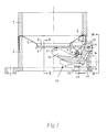
- FIG. 1 shows the upper end of a filler neck 1, its lower end (not shown) into one (also not shown) fuel tank opens.
- the upper opening of the filler neck 1 is using a conventional Fuel cap e.g. via screw or bayonet thread lockable (not shown).
- an insert 2 for assembly a funnel-shaped reducing ring 3 and for storing one whose central opening 4 closes flap 5 used.
- the insert 2 like the reducing ring 3, can also be integrally formed with the filler neck 1.
- the opening 4 of the reducing ring 3 has such a diameter that they only make the passage smaller, for the delivery of lead free petrol in certain fuel nozzle filler pipes enables.
- the closure flap 5 can therefore lead from unleaded fuel Fuel nozzles swung down to the side are, and is therefore also referred to as "lead-free valve".
- the pivoting of the closure flap 5 takes place via attached Bearing brackets 6, which from a in the side wall 7th of the filler neck 1 mounted shaft 8 are penetrated.
- a valve device is located to the side of the filler neck end 1 11 (Fig. 2) via means not shown supported, for example flanged.
- the valve device 11 is part of a so-called ORVR system (on board refueling vapor recovery system) and controls them during the refueling process occurring gas flows and liquid levels.
- ORVR system on board refueling vapor recovery system
- the container is generated by the combustion supply gases during driving which flushes out the fuel residue from the activated carbon filter dissolve out and incinerate.
- the valve device 11 is, for example, a 4/2-way valve with four connections 12-15.
- the connection leads in detail 15 to the activated carbon filter;
- the large-diameter connection 12 is connected directly to the filler neck end 1, vents the fuel tank into the collecting container during refueling and is closed while driving;
- the small-diameter Port 13 is also at the end of the filler neck 1 connected, but only open when driving to vent the filler neck and to equalize the pressure in the To provide filler neck;
- port 14 connects to one Gas collecting space at the top of the fuel tank is closed during refueling and opened while driving, and provides the overfill prevention function known to those skilled in the art.
- valve device 11 Switching the valve device 11 between the refueling position on the one hand (flap 5 open) and driving on the other hand (flap 5 closed) takes place via a push-to-operate control element 16 (valve spindle, Valve tappet) of the valve device 11 and a generally with 17 designated mechanism for implementing the pivoting movement the shutter 5 in the sliding movement of the control element 16. Due to the limited space, the mechanism 17 on the one hand be compact, on the other hand the introduction any transverse forces in the control element 16, i.e. of forces, which run normal to the direction of shift of the control element 16, prevent.
- a push-to-operate control element 16 valve spindle, Valve tappet
- the mechanism 17 has a toggle 18 on which at one end 19 at 20 radially outside the shaft 8 is articulated in the side wall 7 and with his other end 21 slides on the underside of the flap 5.
- Be with 22 designated knee section overlaps the shaft 8 of the Flap 5 and cooperates with a carriage 23 which in the Side wall 7, more precisely in tongue and groove guides 24 (Fig. 4), linearly guided normal to the pivot axis of the flap 5 is.
- the carriage 23 is on its outside with a contact surface 25 for the end of the control element 16 of the valve device 11 provided and actuated this during its outward movement.
- the carriage 23 is U-shaped in plan view (FIG. 2), its two legs 23 'each via the tongue and groove guides 24 are guided in the side wall 7, and its central web 26 presents the contact surface 25. This makes it possible for the toggle lever 18 in the central recess of the Slide 23 moves.
- the knee section 22 of the toggle lever 18 can directly on the Act web 26 of the carriage 23.
- the knee section 22 is equipped with lateral pins 27, which in scenes 28 (Fig. 3) on the inside of the Engage the legs of the carriage 23.
- the two legs 23 'of the carriage 23 are resilient Locking hook 29 equipped when installing for the first time the device when the carriage 23 first from the outside inserted into the side wall 7 with the aid of the tongue and groove guides 24 is, at the beginning of the insertion process on the shaft 8 Flap 5 spring forward and thereby a loss protection for the carriage 29, as long as the valve device 11 is still is not attached to the mechanism 17, offer.
- the sliding axis of the carriage 23 and the control element 16 need not, as shown in Fig. 1 perpendicular to the axis of the Filler neck 1 run, but can also be inclined be inclined as long as they are normal to the pivot axis of the flap 5 runs.
Landscapes
- Engineering & Computer Science (AREA)
- Transportation (AREA)
- Sustainable Development (AREA)
- Sustainable Energy (AREA)
- Chemical & Material Sciences (AREA)
- Combustion & Propulsion (AREA)
- Life Sciences & Earth Sciences (AREA)
- Mechanical Engineering (AREA)
- Cooling, Air Intake And Gas Exhaust, And Fuel Tank Arrangements In Propulsion Units (AREA)
- Fuel-Injection Apparatus (AREA)
- Preventing Unauthorised Actuation Of Valves (AREA)
- Closures For Containers (AREA)
- Lock And Its Accessories (AREA)
- Feeding And Controlling Fuel (AREA)
Applications Claiming Priority (3)
| Application Number | Priority Date | Filing Date | Title |
|---|---|---|---|
| AT1748/97 | 1997-10-15 | ||
| AT0174897A AT406578B (de) | 1997-10-15 | 1997-10-15 | Vorrichtung zur schiebbetätigung einer orvr-ventileinrichtung durch die bewegung einer tankverschlussklappe |
| AT174897 | 1997-10-15 |
Publications (3)
| Publication Number | Publication Date |
|---|---|
| EP0911202A2 true EP0911202A2 (fr) | 1999-04-28 |
| EP0911202A3 EP0911202A3 (fr) | 1999-11-10 |
| EP0911202B1 EP0911202B1 (fr) | 2002-10-23 |
Family
ID=3520158
Family Applications (1)
| Application Number | Title | Priority Date | Filing Date |
|---|---|---|---|
| EP98890275A Expired - Lifetime EP0911202B1 (fr) | 1997-10-15 | 1998-09-30 | Dispositif pour le mouvement coulissant d'un dispositif de soupape ORVR commandé par le mouvement d'un bouchon de réservoir de carburant |
Country Status (4)
| Country | Link |
|---|---|
| US (1) | US6044864A (fr) |
| EP (1) | EP0911202B1 (fr) |
| AT (2) | AT406578B (fr) |
| DE (1) | DE59806036D1 (fr) |
Families Citing this family (2)
| Publication number | Priority date | Publication date | Assignee | Title |
|---|---|---|---|---|
| US7549443B2 (en) * | 2003-12-09 | 2009-06-23 | Illinois Tool Works Inc. | Fuel shut-off valve assembly with associated components and methods of making and assembling the same |
| US8998170B2 (en) * | 2012-12-07 | 2015-04-07 | Star Envirotech, Inc. | Adapter for a capless fuel tank filler neck to test a fuel tank for leaks |
Family Cites Families (14)
| Publication number | Priority date | Publication date | Assignee | Title |
|---|---|---|---|---|
| US639582A (en) * | 1899-08-24 | 1899-12-19 | Robert E Kabisch | Beer-tap. |
| US1497054A (en) * | 1921-12-19 | 1924-06-10 | Rodney N Allabach | Automatic shut-off valve |
| US3580414A (en) * | 1968-12-20 | 1971-05-25 | Standard Oil Co | Fueling device for automobiles and the like |
| JPH039467Y2 (fr) * | 1985-02-25 | 1991-03-08 | ||
| DE3544782A1 (de) * | 1985-08-30 | 1987-06-19 | Schulte H J S Gmbh & Co | Verschluss fuer einen benzineinfuellstutzen eines kraftfahrzeuges |
| US4630749A (en) * | 1986-03-18 | 1986-12-23 | General Motors Corporation | Fuel fill tube with vapor vent and overfill protection |
| US4719949A (en) * | 1986-06-30 | 1988-01-19 | Mobil Oil Corporation | Automotive nozzle-actuated refueling emission system shutoff valve |
| US5027868A (en) * | 1986-12-23 | 1991-07-02 | Gt Development Corporation | Vapor recovery systems |
| EP0296618B1 (fr) * | 1987-06-25 | 1990-12-05 | Temtec Fahrzeugtechnik Entwicklungsgesellschaft mbH | Réservoir d'essence autoserrant |
| US4765504A (en) * | 1987-08-31 | 1988-08-23 | General Motors Corporation | Vapor venting valve for vehicle fuel system |
| JPH081134Y2 (ja) * | 1987-12-09 | 1996-01-17 | オーエム工業株式会社 | 自動車給油管 |
| DE4021218A1 (de) * | 1990-07-04 | 1992-01-09 | Blau Kg Kraftfahrzeugtech | Tankfuellstutzen fuer einen treibstofftank |
| JP2937065B2 (ja) * | 1995-03-27 | 1999-08-23 | 三菱自動車工業株式会社 | 燃料貯蔵装置 |
| AT403141B (de) * | 1995-09-19 | 1997-11-25 | Blau Automobiltechnik Gmbh | Verschlussvorrichtung für einen fahrzeugtank-einfüllstutzen |
-
1997
- 1997-10-15 AT AT0174897A patent/AT406578B/de not_active IP Right Cessation
-
1998
- 1998-09-30 AT AT98890275T patent/ATE226522T1/de not_active IP Right Cessation
- 1998-09-30 EP EP98890275A patent/EP0911202B1/fr not_active Expired - Lifetime
- 1998-09-30 DE DE59806036T patent/DE59806036D1/de not_active Expired - Fee Related
- 1998-10-08 US US09/168,573 patent/US6044864A/en not_active Expired - Fee Related
Non-Patent Citations (1)
| Title |
|---|
| None |
Also Published As
| Publication number | Publication date |
|---|---|
| AT406578B (de) | 2000-06-26 |
| US6044864A (en) | 2000-04-04 |
| EP0911202A3 (fr) | 1999-11-10 |
| EP0911202B1 (fr) | 2002-10-23 |
| ATE226522T1 (de) | 2002-11-15 |
| DE59806036D1 (de) | 2002-11-28 |
| ATA174897A (de) | 1999-11-15 |
Similar Documents
| Publication | Publication Date | Title |
|---|---|---|
| AT403141B (de) | Verschlussvorrichtung für einen fahrzeugtank-einfüllstutzen | |
| DE4242228C2 (de) | Tankverschlußsystem für einen Kraftstoffbehälter eines Kraftfahrzeuges | |
| DE4320106C2 (de) | Vorrichtung zur Steuerung der Bewegung eines Fahrzeugschiebedachdeckels | |
| DE102006002064B4 (de) | Fahrzeugdach mit einem oberhalb eines festen Dachabschnitts verschiebbaren Deckel | |
| DE10042460A1 (de) | Versenkbares Dach eines Cabriolet-Fahrzeugs | |
| EP0320643B1 (fr) | Réservoir de carburant | |
| AT407386B (de) | Vorrichtung zum steuern der gasströme und flüssigkeitsniveaus in einem orvr-betankungssystem | |
| DE19911489A1 (de) | Vorrichtung zum Steuern von Fluidströmen beim Betanken | |
| EP0911202B1 (fr) | Dispositif pour le mouvement coulissant d'un dispositif de soupape ORVR commandé par le mouvement d'un bouchon de réservoir de carburant | |
| DE10065947C2 (de) | Öffnungsfähiges Fahrzeugdach | |
| DE10057872A1 (de) | Hardtop-Fahrzeugdach | |
| DE4018197C2 (de) | Kraftfahrzeug mit einem am Unterboden unterhalb des Fahrzeughecks befestigten Kraftstofftank | |
| DE19504922C2 (de) | Ein-Ausstiegsluke für ein Kampffahrzeug, insbesondere einen Kampfpanzer | |
| WO1997008068A1 (fr) | Dispositif de mise a l'air libre pour recipient contenant un liquide | |
| DE3232340C1 (de) | Selbstschliessender Kraftstoffbehaelterverschluss | |
| DE9113488U1 (de) | Vorrichtung zum Reinigen und Entleeren von Getränkeflüssigkeitsleitungen in Zapfanlagen | |
| DE102006042447A1 (de) | Kraftfahrzeug mit einer schwenkbar gelagerten Tankklappe | |
| DE3825192C2 (fr) | ||
| DE202005015050U1 (de) | Torantrieb mit Aufschubsicherung | |
| DE19849947C2 (de) | Automatische Betankungseinrichtung für Kraftfahrzeuge | |
| DE19609188C1 (de) | Betätigungsmechanik für ein öffnungsfähiges Fahrzeugdach | |
| EP0915771B1 (fr) | Dispositif permettant d'empecher le trop-plein d'un reservoir d'essence | |
| DE69611152T2 (de) | Vorrichtung zum Betanken des Kraftstoffbehälters eines Kraftfahrzeuges | |
| AT403563B (de) | Verschlussvorrichtung für einen fahrzeugtank-einfüllstutzen | |
| DE371330C (de) | Behaelterwagen fuer fluessige Brennstoffe |
Legal Events
| Date | Code | Title | Description |
|---|---|---|---|
| PUAI | Public reference made under article 153(3) epc to a published international application that has entered the european phase |
Free format text: ORIGINAL CODE: 0009012 |
|
| AK | Designated contracting states |
Kind code of ref document: A2 Designated state(s): AT DE FR GB IT |
|
| AX | Request for extension of the european patent |
Free format text: AL;LT;LV;MK;RO;SI |
|
| PUAL | Search report despatched |
Free format text: ORIGINAL CODE: 0009013 |
|
| AK | Designated contracting states |
Kind code of ref document: A3 Designated state(s): AT BE CH CY DE DK ES FI FR GB GR IE IT LI LU MC NL PT SE |
|
| AX | Request for extension of the european patent |
Free format text: AL;LT;LV;MK;RO;SI |
|
| 17P | Request for examination filed |
Effective date: 20000407 |
|
| AKX | Designation fees paid |
Free format text: AT DE FR GB IT |
|
| GRAG | Despatch of communication of intention to grant |
Free format text: ORIGINAL CODE: EPIDOS AGRA |
|
| GRAG | Despatch of communication of intention to grant |
Free format text: ORIGINAL CODE: EPIDOS AGRA |
|
| GRAH | Despatch of communication of intention to grant a patent |
Free format text: ORIGINAL CODE: EPIDOS IGRA |
|
| 17Q | First examination report despatched |
Effective date: 20020429 |
|
| GRAH | Despatch of communication of intention to grant a patent |
Free format text: ORIGINAL CODE: EPIDOS IGRA |
|
| GRAA | (expected) grant |
Free format text: ORIGINAL CODE: 0009210 |
|
| AK | Designated contracting states |
Kind code of ref document: B1 Designated state(s): AT DE FR GB IT |
|
| REF | Corresponds to: |
Ref document number: 226522 Country of ref document: AT Date of ref document: 20021115 Kind code of ref document: T |
|
| REG | Reference to a national code |
Ref country code: GB Ref legal event code: FG4D Free format text: NOT ENGLISH |
|
| REF | Corresponds to: |
Ref document number: 59806036 Country of ref document: DE Date of ref document: 20021128 |
|
| GBT | Gb: translation of ep patent filed (gb section 77(6)(a)/1977) |
Effective date: 20021126 |
|
| ET | Fr: translation filed | ||
| PLBE | No opposition filed within time limit |
Free format text: ORIGINAL CODE: 0009261 |
|
| STAA | Information on the status of an ep patent application or granted ep patent |
Free format text: STATUS: NO OPPOSITION FILED WITHIN TIME LIMIT |
|
| 26N | No opposition filed |
Effective date: 20030724 |
|
| PGFP | Annual fee paid to national office [announced via postgrant information from national office to epo] |
Ref country code: DE Payment date: 20040917 Year of fee payment: 7 Ref country code: FR Payment date: 20040917 Year of fee payment: 7 |
|
| PG25 | Lapsed in a contracting state [announced via postgrant information from national office to epo] |
Ref country code: IT Free format text: LAPSE BECAUSE OF NON-PAYMENT OF DUE FEES Effective date: 20050930 |
|
| PG25 | Lapsed in a contracting state [announced via postgrant information from national office to epo] |
Ref country code: DE Free format text: LAPSE BECAUSE OF NON-PAYMENT OF DUE FEES Effective date: 20060401 |
|
| PG25 | Lapsed in a contracting state [announced via postgrant information from national office to epo] |
Ref country code: FR Free format text: LAPSE BECAUSE OF NON-PAYMENT OF DUE FEES Effective date: 20060531 |
|
| REG | Reference to a national code |
Ref country code: FR Ref legal event code: ST Effective date: 20060531 |
|
| PGFP | Annual fee paid to national office [announced via postgrant information from national office to epo] |
Ref country code: GB Payment date: 20090922 Year of fee payment: 12 Ref country code: AT Payment date: 20090916 Year of fee payment: 12 |
|
| GBPC | Gb: european patent ceased through non-payment of renewal fee |
Effective date: 20100930 |
|
| PG25 | Lapsed in a contracting state [announced via postgrant information from national office to epo] |
Ref country code: GB Free format text: LAPSE BECAUSE OF NON-PAYMENT OF DUE FEES Effective date: 20100930 Ref country code: AT Free format text: LAPSE BECAUSE OF NON-PAYMENT OF DUE FEES Effective date: 20100930 |