EP0909973A2 - Treiberschaltung für optischen Elektroabsorptionsmodulator - Google Patents
Treiberschaltung für optischen Elektroabsorptionsmodulator Download PDFInfo
- Publication number
- EP0909973A2 EP0909973A2 EP98106185A EP98106185A EP0909973A2 EP 0909973 A2 EP0909973 A2 EP 0909973A2 EP 98106185 A EP98106185 A EP 98106185A EP 98106185 A EP98106185 A EP 98106185A EP 0909973 A2 EP0909973 A2 EP 0909973A2
- Authority
- EP
- European Patent Office
- Prior art keywords
- impedance
- electro
- voltage
- optical modulator
- driving
- Prior art date
- Legal status (The legal status is an assumption and is not a legal conclusion. Google has not performed a legal analysis and makes no representation as to the accuracy of the status listed.)
- Withdrawn
Links
Images


Classifications
-
- G—PHYSICS
- G02—OPTICS
- G02F—OPTICAL DEVICES OR ARRANGEMENTS FOR THE CONTROL OF LIGHT BY MODIFICATION OF THE OPTICAL PROPERTIES OF THE MEDIA OF THE ELEMENTS INVOLVED THEREIN; NON-LINEAR OPTICS; FREQUENCY-CHANGING OF LIGHT; OPTICAL LOGIC ELEMENTS; OPTICAL ANALOGUE/DIGITAL CONVERTERS
- G02F1/00—Devices or arrangements for the control of the intensity, colour, phase, polarisation or direction of light arriving from an independent light source, e.g. switching, gating or modulating; Non-linear optics
- G02F1/01—Devices or arrangements for the control of the intensity, colour, phase, polarisation or direction of light arriving from an independent light source, e.g. switching, gating or modulating; Non-linear optics for the control of the intensity, phase, polarisation or colour
- G02F1/0121—Operation of devices; Circuit arrangements, not otherwise provided for in this subclass
-
- G—PHYSICS
- G02—OPTICS
- G02F—OPTICAL DEVICES OR ARRANGEMENTS FOR THE CONTROL OF LIGHT BY MODIFICATION OF THE OPTICAL PROPERTIES OF THE MEDIA OF THE ELEMENTS INVOLVED THEREIN; NON-LINEAR OPTICS; FREQUENCY-CHANGING OF LIGHT; OPTICAL LOGIC ELEMENTS; OPTICAL ANALOGUE/DIGITAL CONVERTERS
- G02F1/00—Devices or arrangements for the control of the intensity, colour, phase, polarisation or direction of light arriving from an independent light source, e.g. switching, gating or modulating; Non-linear optics
- G02F1/01—Devices or arrangements for the control of the intensity, colour, phase, polarisation or direction of light arriving from an independent light source, e.g. switching, gating or modulating; Non-linear optics for the control of the intensity, phase, polarisation or colour
- G02F1/015—Devices or arrangements for the control of the intensity, colour, phase, polarisation or direction of light arriving from an independent light source, e.g. switching, gating or modulating; Non-linear optics for the control of the intensity, phase, polarisation or colour based on semiconductor elements having potential barriers, e.g. having a PN or PIN junction
- G02F1/0155—Devices or arrangements for the control of the intensity, colour, phase, polarisation or direction of light arriving from an independent light source, e.g. switching, gating or modulating; Non-linear optics for the control of the intensity, phase, polarisation or colour based on semiconductor elements having potential barriers, e.g. having a PN or PIN junction modulating the optical absorption
- G02F1/0157—Devices or arrangements for the control of the intensity, colour, phase, polarisation or direction of light arriving from an independent light source, e.g. switching, gating or modulating; Non-linear optics for the control of the intensity, phase, polarisation or colour based on semiconductor elements having potential barriers, e.g. having a PN or PIN junction modulating the optical absorption using electro-absorption effects, e.g. Franz-Keldysh [FK] effect or quantum confined stark effect [QCSE]
Definitions
- This invention relates to a driving circuit for an electro-absorption optical modulator. More particularly, the invention relates to a driving circuit for an electro-absorption optical modulator for outputting intensity-modulated signal light by receiving carrier light from a light source and absorbing the carrier light in dependence upon driving voltage.
- An electro-absorption optical modulator (referred to as an "EA modulator) is available as an external modulator for performing the intensity modulation.
- the EA modulator generates intensity-modulated signal light by absorbing carrier light in dependence upon applied voltage (i.e., driving voltage).
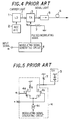
- Fig. 4 is a block diagram showing the general construction of a light transmitter using an EA modulator as the optical modulator.
- the transmitter includes a laser diode (LD) 1 as the light source, a laser diode drive 2 for causing the laser diode to emit light at a constant intensity and including an ACC (Automatic Current Control) circuit, which regulates laser diode driving current to a constant current value, and an ATC (Automatic Temperature Control) circuit for regulating laser diode chip temperature to a constant temperature, an EA modulator 3 for intensity-modulating carrier light from the laser diode by the applied voltage (driving voltage) to effect a conversion to signal light, a modulating signal generating circuit 4 for outputting a pulsed modulating signal based upon "1"s and "0"s of the data signal (input signal IN) and applying the pulsed driving voltage to the EA modulator, an isolator 5 for sending the signal light, which is output by the EA modulator, to an optical fiber 6, and a terminat
- the modulating signal generating circuit 4 is constituted by a differential-type switch and a constant-current source. More specifically, as shown in Fig. 5, the modulating signal generating circuit 4 includes FETs 4a, 4b in a differential pair whose source terminals are tied together and connected to a constant-current source 4c.
- the drain terminal of the FET 4a is connected to ground via a resistor R
- the drain terminal of the FET 4b is connected to the EA modulator 3
- an input signal IN is applied to the gate terminal of the FET 4a
- a signal *IN which is the inverse of the input signal IN, is applied to the gate terminal of the FET 4b.
- Fig. 7 is a diagram useful in describing the operation of the circuit.
- a characteristic curve 11 represents the relationship between output power P 0 of the EA modulator 3 and voltage V EA applied to the EA modulator 3. It will be appreciated that the output power P 0 is approximately inversely proportional to the square of the applied voltage V EA . If the applied voltage V EA is pulse-modulated at values at which the output power P 0 is maximized and at values at which the output power P 0 is approximately minimized, as indicated by the solid line 12 in Fig. 7, then a signal light intensity modulated as indicated at 13 is output by the EA modulator 3.
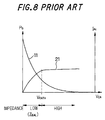
- Fig. 8 shows an electro-absorption static characteristic illustrating the relationship between a photocurrent I PH , which is produced by the EA modulator 3 owing to absorption of carrier light, and the applied voltage V EA , as well as the relationship between the output power P 0 and the applied voltage V EA .
- the applied voltage V EA is plotted along the horizontal axis while the signal light output P 0 and photocurrent I PH are plotted along the vertical axis.
- the output power P 0 of the signal light varies as indicated by a curve 11 as the applied voltage V EA varies.
- the photocurrent I PH developed in the EA modulator 3 increases as indicated by curve 21 as the output power P 0 of the signal line decreases (i.e., as the amount of absorption of the carrier light increases). That is, if the applied voltage V EA is increased, light is absorbed, the output power P 0 decreases and the absorbed light appears as the photocurrent I PH.
- photocurrent I PH is not linear in the relationship with the applied voltage V EA .
- the photocurrent I PH presents a linear characteristic in the region in which the EA voltage V EA is less than V EATH (i.e., in the low-voltage region) and a saturated characteristic in the region in which the EA voltage V EA is greater than V EATH (i.e., in the high-voltage region). If this is considered in terms of the impedance of the EA modulator, the impedance is low in the low-voltage region where the EA voltage V EA is less than V EATH and high in the high-voltage region where the EA voltage V EA is greater than V EATH .
- the 50-ohm terminating resistor is connected in parallel with the EA modulator 3, as shown in Figs. 4 through 6, and the EA modulator 3 performs pulse modulation while impedance is matched with that of the modulating signal generating circuit 4 by this resistor. If the EA modulator 3 is operating at high impedance, then impedance matching is achieved correctly. If the EA modulator 3 operates at low impedance, however, the impedance as seen from the modulating signal generating circuit 4 declines, impedance mismatching occurs and the waveform deteriorates.
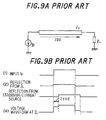
- Figs. 9A and 9B are diagrams useful in describing waveform deterioration in a case where the aforesaid impedance mismatch has occurred.
- a pulsed current source Ip is terminated at an impedance Z L through a transmission line having an impedance Z 0 and exhibiting a propagation delay time of ⁇ pd .
- the conditions which prevail when Z L ⁇ Z 0 holds will be considered.
- the Z L ⁇ Z 0 state represents the state of mismatched impedance.
- reflection is produced by the impedance Z L and by the pulsed current source Ip, as indicated by the waveforms (2), (3) in Fig. 9B, and the waveform of the voltage across the impedance Z L is as indicated by the waveform (4).
- the waveform of the voltage across the impedance Z L has steps on both sides owing to reflection.
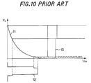
- the EA modulator 3 produces impedance mismatch if it operates at low impedance, as mentioned above. Consequently, a problem which arises is that an EA voltage waveform 12 whose waveform has deteriorated in the manner shown in Fig. 10 is applied to the EA modulator 3 so that the EA modulator 3 outputs signal light 13 the positive-going transition of which has a deteriorated waveform.
- an object of the present invention is to arrange it so that impedance matching can be achieved even in a case where the EA modulator operates at both low and high impedances, thereby eliminating deterioration of the signal light waveform ascribed to impedance mismatch.
- a driving circuit for an electro-absorption optical modulator comprising a driving unit for applying a pulsed driving voltage (a pulsed modulating voltage) to an EA modulator, and a variable impedance unit connected in parallel with the EA modulator for matching impedance with respect to the driving unit, wherein impedance of the variable impedance unit is switched to one value when the driving voltage is applied to the EA modulator and to another value when the driving voltage is not applied to the EA modulator so as to match impedance with respect to the driving unit.
- a pulsed driving voltage a pulsed modulating voltage
- the driving unit is constituted by a constant-current source and a connection switching circuit, wherein (1) when the driving voltage is being applied, the constant-current source is connected by the connection switching circuit to a point at which the electro-absorption optical modulator and the variable impedance unit are connected in parallel with each other, and (2) when the driving voltage is not being applied, the constant-current source is disconnected from the point by the connection switching circuit.
- the variable impedance circuit is constituted by a semiconductor device, such as a diode of FET, that is turned on and off in dependence upon whether the driving voltage is or is not being applied.
- Fig. 1 is a diagram showing the construction of an EA driving circuit according to the present invention.
- the driving circuit includes a driving unit 52 for applying a pulsed driving voltage (pulsed modulating voltage) to an EA modulator 51, and a variable impedance circuit 53 connected in parallel with the EA modulator 51.
- a pulsed driving voltage pulsed modulating voltage
- the driving unit 52 outputs a pulsed modulating signal (current pulses indicated by I pulse ) based upon the "1"s and "0"s of the data signal (input signal IN), and applies the pulsed modulating voltage to the EA modulator 51.
- the driving unit 52 is constituted by a switch having a differential construction and a constant-current source. More specifically, the driving unit 52 includes FETs 52a, 52b in a differential pair whose source terminals are tied together and connected to a constant-current source 52c.
- the drain terminal of the FET 52a is connected to ground via a resistor, the drain terminal of the FET 52b is connected to the EA modulator 51, the input signal IN is applied to the gate terminal of the FET 52a, and a signal *IN, which is the inverse of the input signal IN, is applied to the gate terminal of the FET 52b. If the input signal IN is logical "1", the FET 52a turns on, the FET 52b turns off at the same time, a constant current flows into the FET 52a and the current pulse I pulse is not produced. If the input signal IN is logical "0", the FET 52a turns off, the FET 52b turns on at the same time, a constant current flows into the FET 52b and the current pulse I pulse is generated. Thus, a pulsed modulating signal (the current pulses I pulse ) is generated based upon the "1", "0" logic levels of the input signal.
- the variable impedance circuit 53 changes over impedance automatically depending upon whether the pulsed modulating voltage is or is not being applied to the EA modulator 51, thereby matching impedance with the driving unit 52 at all times. More specifically, the impedance of the variable impedance circuit 53 is varied by the EA voltage V EA so that impedance as seen from the side of the driving unit 52 is made 50 ohms at all times both in the low-voltage region (when the pulsed modulating voltage is not being applied) and high-voltage region (when the pulsed modulating voltage is being applied). As a result, waveform deterioration caused by impedance mismatch does not occur.
- Z EAL represent the impedance of the EA modulator 51 in the low-voltage region
- V EATH the EA voltage which effects the changeover between high and low impedances
- Z EAL is already known since it is the impedance of the EA modulator 51 in the low-voltage region. In the low-voltage region, therefore, it will suffice to decide the impedance of the variable impedance circuit 53 in such a manner that the impedance value given by Equation (1) will be obtained.
- variable impedance circuit 53 controls impedance to obtain the value indicated by Equation (1) in the low-voltage region in which V EA ⁇ V EATH holds and to obtain the value indicated by Equation (2) in the high-voltage region in which V EA > V EATH holds, the impedance as seen from the driving unit 52 can be made 50 ohms at all times and waveform deterioration due to impedance mismatch can be prevented.
- Fig. 2 is a diagram showing the construction of a variable impedance circuit according to a first embodiment of the present invention. Components identical with those shown in Fig. 1 are designated by like reference characters.
- the variable impedance circuit 53 includes a resistor 61 having a resistance of 50 ohms, a resistor 62 having a resistance of R1 ohms, and a diode 63 connected in parallel with the resistor 62.
- the variable impedance circuit 53 is constructed by connecting a parallel circuit comprising the diode 63 and resistor 62 in series with the 50-ohm resistor 61.
- Equation (1) 50 + R1
- the diode 63 turns on. Since the internal impedance of the diode 63 is approximately 0 ohms, the impedance Z of the variable impedance circuit 53 becomes 50 ohms, satisfying Equation (2).
- Fig. 3 is a diagram showing the construction of a variable impedance circuit according to a second embodiment of the present invention. Components identical with those shown in Fig. 1 are designated by like reference characters.
- variable impedance circuit 53 includes a resistor 71 having a resistance of R1 ohms, and a FET 72 connected in parallel with the resistor 71.
- the gate and drain terminals of the FET 72 are connected to ground and the source terminal is connected to one end of the resistor 71 and to the anode side of the EA modulator 51.
- variable impedance circuit includes a diode or a FET.
- the variable impedance circuit can be constructed using a transistor or other semiconductor switch.
- a transistor can be substituted for the diode in Fig. 2 and it can be so arranged that the transistor turns off in the low-voltage region where V EA ⁇ V EATH holds and the high-voltage region where V EA > V EATH holds.
- the resistance value for impedance matching is 50 ohms, this value does not impose a limitation upon the invention.
- a driving circuit for an electro-absorption optical modulator includes a driving unit for applying a pulsed driving voltage (a pulsed modulating voltage) to an EA modulator, and a variable impedance unit connected in parallel with the EA modulator for matching impedance with respect to the driving unit, wherein the impedance of the variable impedance unit is switched when a voltage is and is not applied to the EA modulator so as to match impedance with the driving unit.
- variable impedance circuit can be constructed in simple fashion using a semiconductor device, such as a diode or FET, that is turned on and off in dependence upon whether a driving voltage is or is not being applied.
- a semiconductor device such as a diode or FET
Landscapes
- Physics & Mathematics (AREA)
- Nonlinear Science (AREA)
- General Physics & Mathematics (AREA)
- Optics & Photonics (AREA)
- Optical Modulation, Optical Deflection, Nonlinear Optics, Optical Demodulation, Optical Logic Elements (AREA)
- Semiconductor Lasers (AREA)
- Optical Communication System (AREA)
Applications Claiming Priority (3)
| Application Number | Priority Date | Filing Date | Title |
|---|---|---|---|
| JP28004797 | 1997-10-14 | ||
| JP28004797A JP3816648B2 (ja) | 1997-10-14 | 1997-10-14 | 電界吸収型光変調器の駆動回路 |
| JP280047/97 | 1997-10-14 |
Publications (2)
| Publication Number | Publication Date |
|---|---|
| EP0909973A2 true EP0909973A2 (de) | 1999-04-21 |
| EP0909973A3 EP0909973A3 (de) | 2000-05-03 |
Family
ID=17619564
Family Applications (1)
| Application Number | Title | Priority Date | Filing Date |
|---|---|---|---|
| EP98106185A Withdrawn EP0909973A3 (de) | 1997-10-14 | 1998-04-03 | Treiberschaltung für optischen Elektroabsorptionsmodulator |
Country Status (3)
| Country | Link |
|---|---|
| US (1) | US5930022A (de) |
| EP (1) | EP0909973A3 (de) |
| JP (1) | JP3816648B2 (de) |
Cited By (1)
| Publication number | Priority date | Publication date | Assignee | Title |
|---|---|---|---|---|
| WO2003034558A1 (fr) * | 2001-10-11 | 2003-04-24 | Hamamatsu Photonics K.K. | Circuit d'attaque d'un element electroluminescent |
Families Citing this family (16)
| Publication number | Priority date | Publication date | Assignee | Title |
|---|---|---|---|---|
| US6788447B2 (en) * | 2002-08-07 | 2004-09-07 | Triquint Technology Holding Co. | Off-chip matching circuit for electroabsorption optical modulator |
| JP4295546B2 (ja) * | 2003-04-11 | 2009-07-15 | 三菱電機株式会社 | 差動駆動型半導体光変調器 |
| JP2004325495A (ja) * | 2003-04-21 | 2004-11-18 | Nec Compound Semiconductor Devices Ltd | 光半導体装置、これを備える光通信用ボード及び光通信用モジュール |
| ATE301843T1 (de) * | 2003-06-16 | 2005-08-15 | Cit Alcatel | Elektro-optischer absorptionsmodulator mit begrenzer für das steuersignal |
| US7373090B2 (en) * | 2004-03-26 | 2008-05-13 | Intel Corporation | Modulator driver circuit with selectable on-chip termination |
| JP4578164B2 (ja) * | 2004-07-12 | 2010-11-10 | 日本オプネクスト株式会社 | 光モジュール |
| US20060221427A1 (en) * | 2005-03-31 | 2006-10-05 | Wu Xin M | Impedance matching circuit for optical transmitter |
| US20070009267A1 (en) * | 2005-06-22 | 2007-01-11 | Crews Darren S | Driving a laser using an electrical link driver |
| JP4506640B2 (ja) * | 2005-10-19 | 2010-07-21 | 住友電気工業株式会社 | 半導体レーザ駆動回路 |
| JP5157457B2 (ja) * | 2008-01-08 | 2013-03-06 | 富士通株式会社 | 半導体素子の制御回路 |
| US8289748B2 (en) * | 2008-10-27 | 2012-10-16 | Seagate Technology Llc | Tuning a variable resistance of a resistive sense element |
| US8903254B2 (en) * | 2011-05-24 | 2014-12-02 | Source Photonics, Inc. | Low power consumption, long range, pluggable transceiver, circuits and devices therefor, and method(s) of using the same |
| JP2014160176A (ja) * | 2013-02-20 | 2014-09-04 | Sumitomo Electric Ind Ltd | 駆動回路 |
| US9197318B1 (en) | 2013-06-07 | 2015-11-24 | Pmc-Sierra Us, Inc. | Apparatus and method for modulating a laser beam and sensing the optical power thereof |
| JP6852302B2 (ja) | 2016-08-19 | 2021-03-31 | 富士通株式会社 | 周波数特性調整回路、これを用いた光送信器、及び光トランシーバ |
| CN109001919B (zh) * | 2018-09-14 | 2025-03-04 | 昂纳科技(深圳)集团股份有限公司 | 一种光滤波器的驱动电路及驱动系统 |
Family Cites Families (7)
| Publication number | Priority date | Publication date | Assignee | Title |
|---|---|---|---|---|
| JP3008608B2 (ja) * | 1991-10-31 | 2000-02-14 | 富士通株式会社 | 電界吸収型光変調器駆動方法 |
| DE4443630A1 (de) * | 1994-12-08 | 1996-06-13 | Sel Alcatel Ag | Optischer Modulatorschaltkreis |
| JPH08316580A (ja) * | 1995-05-18 | 1996-11-29 | Fujitsu Ltd | 電界吸収型光変調器の駆動回路及び該光変調器を備えた光送信機 |
| JPH09181682A (ja) * | 1995-12-26 | 1997-07-11 | Fujitsu Ltd | 光変調器の駆動回路及び光送信機 |
| JP2807651B2 (ja) * | 1996-01-17 | 1998-10-08 | 株式会社エイ・ティ・アール光電波通信研究所 | 半導体電界吸収型光変調装置 |
| JPH09246633A (ja) * | 1996-03-06 | 1997-09-19 | Mitsubishi Electric Corp | 光通信用光源装置 |
| JPH09252164A (ja) * | 1996-03-15 | 1997-09-22 | Mitsubishi Electric Corp | レーザダイオードモジュール |
-
1997
- 1997-10-14 JP JP28004797A patent/JP3816648B2/ja not_active Expired - Fee Related
-
1998
- 1998-03-13 US US09/041,760 patent/US5930022A/en not_active Expired - Fee Related
- 1998-04-03 EP EP98106185A patent/EP0909973A3/de not_active Withdrawn
Cited By (2)
| Publication number | Priority date | Publication date | Assignee | Title |
|---|---|---|---|---|
| WO2003034558A1 (fr) * | 2001-10-11 | 2003-04-24 | Hamamatsu Photonics K.K. | Circuit d'attaque d'un element electroluminescent |
| US7075338B2 (en) | 2001-10-11 | 2006-07-11 | Hamamatsu Photonics K.K. | Light emitting element driving circuit with current mirror circuit |
Also Published As
| Publication number | Publication date |
|---|---|
| EP0909973A3 (de) | 2000-05-03 |
| US5930022A (en) | 1999-07-27 |
| JPH11119175A (ja) | 1999-04-30 |
| JP3816648B2 (ja) | 2006-08-30 |
Similar Documents
| Publication | Publication Date | Title |
|---|---|---|
| US5930022A (en) | Driving circuit for electro-absorption optical modulator | |
| US4243951A (en) | High repetition rate driver circuit for modulation of injection lasers | |
| US5706116A (en) | Drive circuit optical modulator and optical transmitter | |
| US7570680B2 (en) | Laser diode driver with multiple modulation current source | |
| US6242870B1 (en) | Light emitting device driving circuit | |
| US5822685A (en) | Modulating reflector circuit | |
| US8705979B2 (en) | LD driver with an improved falling edge of driving signal and optical transmitter providing the same | |
| US5394261A (en) | Optical communication system and transmitting apparatus for use therein | |
| US20050105574A1 (en) | Laser driver for optical communication network | |
| US5732097A (en) | Modulating circuit for semiconductor optical modulator | |
| EP0540331B1 (de) | Vorrichtung und Verfahren zur Ansteuerung eines Lichtmodulators mit Elektroabsorption | |
| US5521933A (en) | Backmatched laser diode driver | |
| EP0886350B1 (de) | Hochgeschwindigkeitstreiber für nicht polarisierte Halbleiter-Diodenlaser bei Hochgeschwindigkeits-Digitalübertragung | |
| US5343323A (en) | Lan electro-optical interface | |
| EP1030486A2 (de) | Treiberschaltung sowie Modul zur optischen Übertragung | |
| US6542008B1 (en) | System and method for providing an impedance match of an output buffer to a transmission line | |
| US7280574B1 (en) | Circuit for driving a laser diode and method | |
| US8107813B2 (en) | Drive circuit and optical switch | |
| EP1042875B1 (de) | Optischer sender | |
| US6922075B1 (en) | Low power driver circuitry | |
| JP2707837B2 (ja) | 半導体レーザ駆動回路 | |
| US7499603B1 (en) | Range extended electrooptic modulator | |
| Ebben et al. | High-power, high-data-rate laser diode transmitter | |
| US20040197106A1 (en) | Optical transmitter and optical module | |
| JP2707838B2 (ja) | 半導体レーザ駆動回路 |
Legal Events
| Date | Code | Title | Description |
|---|---|---|---|
| PUAI | Public reference made under article 153(3) epc to a published international application that has entered the european phase |
Free format text: ORIGINAL CODE: 0009012 |
|
| AK | Designated contracting states |
Kind code of ref document: A2 Designated state(s): DE FR GB |
|
| AX | Request for extension of the european patent |
Free format text: AL;LT;LV;MK;RO;SI |
|
| PUAL | Search report despatched |
Free format text: ORIGINAL CODE: 0009013 |
|
| AK | Designated contracting states |
Kind code of ref document: A3 Designated state(s): AT BE CH CY DE DK ES FI FR GB GR IE IT LI LU MC NL PT SE |
|
| AX | Request for extension of the european patent |
Free format text: AL;LT;LV;MK;RO;SI |
|
| RIC1 | Information provided on ipc code assigned before grant |
Free format text: 7G 02F 1/01 A, 7H 04B 10/155 B, 7H 04B 10/18 B |
|
| 17P | Request for examination filed |
Effective date: 20001025 |
|
| AKX | Designation fees paid |
Free format text: DE FR GB |
|
| 17Q | First examination report despatched |
Effective date: 20041214 |
|
| RIC1 | Information provided on ipc code assigned before grant |
Ipc: 7H 04B 10/18 B Ipc: 7H 04B 10/155 A |
|
| STAA | Information on the status of an ep patent application or granted ep patent |
Free format text: STATUS: THE APPLICATION IS DEEMED TO BE WITHDRAWN |
|
| 18D | Application deemed to be withdrawn |
Effective date: 20041102 |